Chrysler 300M, Dodge Interpid. Manual - part 7
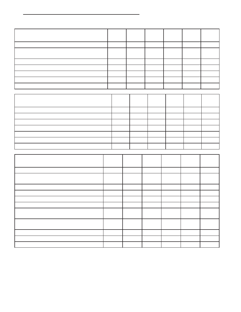
Kilometers
91 000
96 000
101000
106000
110000
115000
(Miles)
(57,000)
(60,000)
(63,000)
(66,000)
(69,000)
(72,000)
Change engine oil and engine oil filter.
X
X
X
X
X
X
Inspect the air cleaner filter and replace if
required.*
X
X
X
X
X
Replace the air cleaner filter.
X
Inspect the front and rear brake linings and rotors.
X
X
Replace the drive belts.
X
Check and replace, if necessary, the PCV valve.* ‡
X
Change the automatic transaxle fluid and filter.
X
Kilometers
120000
125000
130000
134000
139000
144000
(Miles)
(75,000)
(78,000)
(81,000)
(84,000)
(87,000)
(90,000)
Change engine oil and engine oil filter.
X
X
X
X
X
X
Inspect the air cleaner filter
and replace if required.*
X
X
X
X
Replace the air cleaner filter.
*
X
Replace the air cleaner filter.
X
Adjust the drive belt tension.
X
Inspect the front and rear brake linings and rotors.
X
X
Check and replace, if necessary, the PCV valve.
* ‡
X
Kilometers
149000
154000
158000
160000
163000
168000
(Miles)
(93,000)
(96,000)
(99,000)
(100,000) (102,000)
(105,000)
Change engine oil and engine oil filter.
X
X
X
X
X
Inspect the air cleaner filter
and replace if
required.*
X
X
X
X
Replace the air cleaner filter.
X
Inspect the front and rear brake linings and rotors.
X
Change the automatic transaxle fluid and filter.
X
Flush and replace the engine coolant.
X
Replace the engine timing belt
(Federal
Emissions).
X
Replace the engine timing belt
(California
Emissions).
X
Replace the spark plugs.
X
Adjust the drive belt tension.
X
Change the differential fluid.
X
* This maintenance is recommended by the manu-
facture to the owner but is not required to maintain
the emissions warranty.
‡ This maintenance is not required if previously
replaced.
Inspection and service should also be performed
anytime a malfunction is observed or suspected.
Retain all receipts.
WARNING: You can be badly injured working on or
around a motor vehicle. Do only that service work
for which you have the knowledge and the right
equipment. If you have any doubt about your ability
to perform a service job, take your vehicle to a
competent mechanic.
LH
LUBRICATION & MAINTENANCE
0 - 13
MAINTENANCE SCHEDULES (Continued)