Acura TSX / Honda Accord CL. Manual - part 55


  Index      Acura     Acura TSX 2004-2008 / Honda Accord CL 2006-2008 - service repair manual


Search            copyright infringement  


Content   ..  53  54  55  56   ..


Acura TSX / Honda Accord CL. Manual - part 55


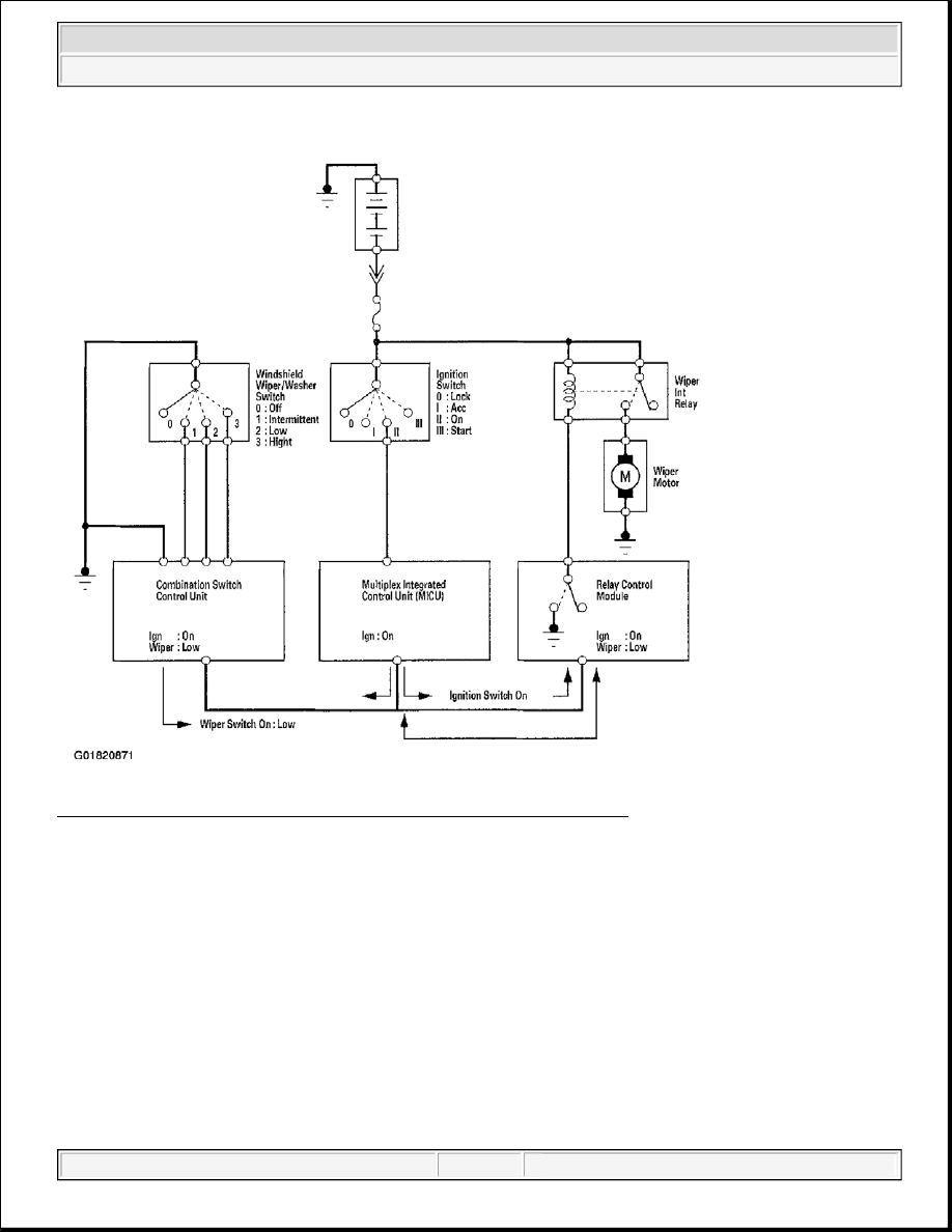
Fig. 4: Combination Switch Control Unit Monitoring The Wiper Switch 

"CONNECTED" ECUS 

Several ECUs are connected to each of the two networks. The Gauge Control Module is part of both networks 
since it is the "Gateway" between them. Below is a list of ECUs and the network they are connected to. 

B-CAN ECUS 

z

Gauge Control Module  

z

Relay Control Module  

z

Multiplex Integrated Control Unit (MICU)  

z

Door Multiplex Control Unit  

z

Combination Switch Control Unit  


2004 Acura TSX 

2004 ACCESSORIES & EQUIPMENT Multiplex Integrated Control System - TSX


z

Climate Control Unit  

F-CAN ECUS 

z

Gauge Control Module  

z

ECM/PCM  

z

Navigation Control Unit  

z

VSA (Vehicle Stability Assist)  

Fig. 5: Network Schematic 

NETWORK "LOSS OF COMMUNICATION" ERROR CHECKING 

The B-CAN and F-CAN systems send messages to each other to check the integrity of the network 
communication circuit. They do this by sending a specific digital message out after an event. For example, 
turning the ignition switch to ON. After the switch to ON, all the ECUs on the communication circuit expect to 
receive a message from other specific units within a specified amount of time. If the message is not received, 
the ECU will transmit a DTC reporting that the control units did not communicate. 

EXAMPLE OF COMMUNICATION CIRCUIT TEST 

Normal Circuit 

1. Ignition switch turned ON.  

2. The door multiplex control unit transmits a door switch signal.  

3. The multiplex integrated control unit (MICU), relay control module and gauge control module receive the 

door lock switch signal.  

4. Communication circuit test is passed. 


2004 Acura TSX 

2004 ACCESSORIES & EQUIPMENT Multiplex Integrated Control System - TSX


Since the door lock switch message was received by all the ECUs expecting to receive a signal, the 
communication circuit between those units is OK. There are multiple signal sent and received by each ECU 
during this time to insure that the communication circuit is intact. 

Failed Circuit 

1. Ignition switch is turned ON.  

2. The door multiplex control unit transmits a door switch signal.  

3. The multiplex integrated control unit (MICU), relay control module and gauge control module expect to 

receive the door lock switch signal, but since there is a break in the communication circuits, it is not 
received.  

4. Each ECU that expects to receive the door lock switch signal from the door multiplex control unit will 

transmit DTCs for the signal that it did not receive.  

Fig. 6: Example Of Failed Circuit 

Since there is a break in the communication circuit, the door lock switch signal could not be received by the 
gauge control module, multiplex integrated control unit (MICU) or the relay control module. Each of these units 
will set "loss of communication" error codes for the signal(s) they did not receive. There may be multiple 
communication DTCs if the unit that has become disconnected from the network would normally transmit 
multiple messages during the communication line test. For example, the door multiplex control unit sends 
keyless panic signal and door lock switch signal during the communication circuit test. 

DIAGNOSTIC TROUBLE CODES 

There are three DTC types used by the CAN networks.


2004 Acura TSX 

2004 ACCESSORIES & EQUIPMENT Multiplex Integrated Control System - TSX


Fig. 7: CAN Networks Diagnostic Trouble Code Type Table 

TROUBLESHOOTING THE CAN CIRCUIT RELATED PROBLEMS 

Using the HDS (Preferred method) 

1. Go to B-CAN System Diagnosis Test Mode A to check for "Connected units" and DTCs (see B-CAN 

SYSTEM DIAGNOSIS TEST MODE A ).  

2. If no DTCs are retrieved, go to B-CAN System Diagnosis Test Mode C or D.  

Without the HDS (Should be used only if HDS is unavailable) 

1. Check for communication circuit problems using B-CAN System Diagnosis Test Mode 1 (see B-CAN 

SYSTEM DIAGNOSIS TEST MODE A ).  

2. Check for DTCs while in Mode 1 (see B-CAN SYSTEM DIAGNOSIS TEST MODE A ).  

3. Sort, and then troubleshoot the DTCs in the order below. Refer to the DTC troubleshooting Index for 

DTC descriptions. 

1st: Internal error and voltage failure DTCs  

2nd: Loss of communication DTCs  

3rd: Signal error DTCs  

4. If no DTCs are retrieved, use B-CAN System Diagnosis Test Mode 2 to check all inputs related to failure 

(see B-CAN SYSTEM DIAGNOSIS TEST MODE A ).  

Loss of Communication DTC cross-reference chart 

When an ECU is unable to communicate with the other ECUs on the circuit, the other units will set loss of 
communication DTCs. Use this chart to find the control unit that is not communicating.  

1. Find the Transmitting Unit that is in the same row as all of the loss of communication DTCs retrieved.  

2. Perform the input test for the transmitting unit. 


2004 Acura TSX 

2004 ACCESSORIES & EQUIPMENT Multiplex Integrated Control System - TSX


Content   ..  53  54  55  56   ..