FANUC CNC Manual
FANUC CNC Manual
1 Contents
2
OVERVIEW OF CNC TRAINING IN DFAB ------------------------------------------------------------------------ 3
2.1
PREREQUISITES------------------------------------------------------------------------------------------------------------------ 3
2.2
READ FANUC OPERATORS MANUAL -------------------------------------------------------------------------------------- 3
2.3
CNC LEVEL 1-------------------------------------------------------------------------------------------------------------------- 3
2.4
CNC LEVEL 2-------------------------------------------------------------------------------------------------------------------- 4
2.5
CNC LEVEL 3-------------------------------------------------------------------------------------------------------------------- 5
3
SAFETY ----------------------------------------------------------------------------------------------------------------------- 6
3.1
GENERAL FANUC CNC MACHINE SAFETY------------------------------------------------------------------------------- 6
3.2
MACHINE CRASH / ACCIDENT REPORTING ------------------------------------------------------------------------------- 6
4
FUNDAMENTAL CONCEPTS ----------------------------------------------------------------------------------------- 7
4.1
AXIS OF MOTION --------------------------------------------------------------------------------------------------------------- 7
4.2
G CODE PROGRAMING WORDS AND SYNTAX----------------------------------------------------------------------------- 7
4.3
OFFSETS ------------------------------------------------------------------------------------------------------------------------ 11
5
CNC TOOLING FOR WOOD, PRIMARILY ------------------------------------------------------------------------14
5.1
DRILL VS. MILL ---------------------------------------------------------------------------------------------------------------- 14
5.2
TOOL LOAD-------------------------------------------------------------------------------------------------------------------- 14
5.3
FLUTE TYPE-------------------------------------------------------------------------------------------------------------------- 15
5.4
TOOL PROFILE ---------------------------------------------------------------------------------------------------------------- 16
5.5
TOOL HOLDERS --------------------------------------------------------------------------------------------------------------- 16
5.6
FEEDS AND SPEEDS ---------------------------------------------------------------------------------------------------------- 17
5.7
WORK HOLDING-------------------------------------------------------------------------------------------------------------- 18
6
CREATE A CAM FILE ---------------------------------------------------------------------------------------------------19
6.1
DRAWING ---------------------------------------------------------------------------------------------------------------------- 19
6.2
RESERVED WORK OFFSETS FOR FANUC IN DFAB--------------------------------------------------------------------- 19
6.3
TOOLPATH BASICS ------------------------------------------------------------------------------------------------------------ 20
6.4
SIMULATION ------------------------------------------------------------------------------------------------------------------- 21
6.5
CHECKING GCODE ----------------------------------------------------------------------------------------------------------- 21
6.6
SAVE A PROGRAM ON THE NETWORK DRIVE --------------------------------------------------------------------------- 23
7
ALL THOSE BUTTONS! ----------------------------------------------------------------------------------------------- 24
7.1
CONTROL PANEL ------------------------------------------------------------------------------------------------------------- 25
7.2
MACHINE PANEL ------------------------------------------------------------------------------------------------------------- 26
8
MACHINE OPERATION ---------------------------------------------------------------------------------------------- 29
8.1
POWER UP---------------------------------------------------------------------------------------------------------------------- 29
8.2
QUICK REVIEW OF NOMENCLATURE ------------------------------------------------------------------------------------- 29
8.3
LOAD AND RUN A FILE ------------------------------------------------------------------------------------------------------ 29
8.4
SPINDLE WARMUP ------------------------------------------------------------------------------------------------------------ 32
8.5
STORE A WORK OFFSET (M402) ------------------------------------------------------------------------------------------- 32
8.6
JOG MODE --------------------------------------------------------------------------------------------------------------------- 33
8.7
SOME COMMON MISTAKES ------------------------------------------------------------------------------------------------- 33
8.8
CLEAN UP ---------------------------------------------------------------------------------------------------------------------- 33
9
ADVANCED MACHINE OPERATION ---------------------------------------------------------------------------- 34
9.1
STOP AND JOG AWAY, RETURN AND CONTINUE CUTTING ----------------------------------------------------------- 34
1
9.2
MAKE A RELATIVE MEASUREMENT --------------------------------------------------------------------------------------- 34
9.3
STORE A TOOL LENGTH OFFSET ------------------------------------------------------------------------------------------ 35
9.4
VIEW OR MODIFY THE VALUES STORED IN A WORK OFFSET-------------------------------------------------------- 36
10
ALARMS AND RECOVERY ------------------------------------------------------------------------------------------- 37
10.1
SOFT OVER-TRAVEL ALARM------------------------------------------------------------------------------------------------ 37
10.2
HARD OVER-TRAVEL ALARM ---------------------------------------------------------------------------------------------- 37
10.3
PAUSED IN THE MIDDLE OF A TOOL CHANGE------------------------------------------------------------------------- 37
11
REFERENCE-------------------------------------------------------------------------------------------------------------- 39
11.1
I/O CHANNELS --------------------------------------------------------------------------------------------------------------- 39
11.2
COMMON PARAMETERS------------------------------------------------------------------------------------------------------ 39
11.3
G CODES (UNABRIDGED) --------------------------------------------------------------------------------------------------- 40
11.4
M CODES (UNABRIDGED) --------------------------------------------------------------------------------------------------- 42
11.5
TOOL SIZE SHAPE AND SPEED FOR HSD SPINDLE --------------------------------------------------------------------- 43
2
2 Overview of CNC Training in dFab
We all learn at various speeds and all have diverse existing skill sets. Take your time and have fun!
2.1 Prerequisites
• Understanding of CAD software used in dFab is fundamental in using this equipment. You must have a
foundation in Rhino3d, Fusion360 or Inventor. Approximately 6 months to a year of heavy use in the
software is sufficient.
• Understanding of why you want to use a CNC machine and what it does.
• Other rapid prototyping experience such as laser cutting and 3d printing
• Understanding of Windows file structure and how to access a server
2.2 Read FANUC Operators Manual
Estimated Time: 1-3 Hours independent work
Please read, take notes and comment on this document. A printed copy is available in dFab or upon request
for current MICA students. This is a working document and we would like to make it better, your input
matters!
2.3 CNC Level 1
Learn Through Coursework
Students are only permitted to use the CNC under direct supervision of their training faculty in Level 1.
Training faculty (Level 3) or Level 3 Tech scheduled for that purpose must be present at the machine while
any student in Level 1 is using the CNC.
2.3.1 Hands on Introduction
Prior to taking any tests or even performing any reading, you may be introduced to the CNC on a superficial
level so that the concepts and procedures in training are more meaningful. The files are carefully prepared by
your faculty member, and they will guide you through responsible and safe machine operation as well as
discus any safety risks associated with this specific task. Students are not permitted to generate their own files
at this time. Tasks students may perform after this instruction and under direct faculty supervision include:
Jogging the machine, loading the file, punching into the MDI. Faculty will demonstrate operator position and
run the file.
2.3.2 Introduction to CAM and Toolpaths
In this coursework you will learn about:
• Setting Stock in your file
•
2d operations including profiling, pocketing and engraving
•
Tooling, tool offsets, climb cutting
•
Work zero, fixtures, work holding
•
Simulations and checking for collisions
•
Axial and Radial tool load
•
Entry and Exit/Linking parameters
3
Take notes in your coursework. To work independently you will be expected to know all of the above
concepts.
2.3.3 Written Test
After reading this manual, take the CNC Test 1. You must complete the test with a 100% score to operate the
machine. The test is not graded on your transcript and you may take the test as many times as you would like
to achieve a perfect score. You will be emailed a response with a copy of your test. Click “VIEW SCORE” to
see how you did, and click “Edit response” to change your answers. Successfully achieving a perfect score on
the written test is mandatory before students can operate the machine in class.
2.3.4 First Operation
We will review the manual, cover safety and have time for questions. After a demonstration, each student will
operate the machine under direct supervision of their training faculty during class or CNC Level 3 tech
scheduled for that purpose to cut a file prepared by the student. We will review jogging the machine, then
cover how to perform a tool change with the MDI and finally run a job on the machine.
Topics Covered: Jog Mode, MDI, Feed Override, Emergency Stop, Reset, Loading Files, Work Offsets, Tool
Offsets, Control Navigation, Work Holding/Fixtures.
2.3.5 Practice
Estimated Time: 2-10 jobs
Create your own files including a design file and all CAM work. Stay within your existing skill set! Work with
your instructor and have them review your work before each cut. Your faculty will supervise cuts in this stage.
Please wait to buy material until after a consultation with your instructor after you believe you have
completed a good set of toolpaths to cut your part, often considerable changes are desired by the student in
this initial meeting.
Try to do as much as possible. If your instructor shows you how to set something up or how to create a
toolpath, break it down and re-do it right after your meeting so you can really grasp the concept.
Be patient and try to learn one thing at a time. Learning this content can be overwhelming due to all the
seemingly minute details. The best practice for overcoming this learning curve is to make multiple small or
short cuts on consecutive days. Focus on learning the workflow, then apply it to your work.
2.4 CNC Level 2
Use of CNC after taking CNC Coursework
Complete the below requirements to use CNC outside of class time or after the course covering CNC ends.
2.4.1 Written Test
You must complete the Level 2 Test with a 100% score to operate the machine after taking coursework that
covers this content. The test is not graded on your transcript and you may take the test as many times as you
would like to achieve a perfect score. You will be emailed a response with a copy of your test. Click “VIEW
SCORE” to see how you did, and click “Edit response” to change your answers.
4
2.4.2 Practical Test
After successfully achieving a perfect score on the CNC Level 2 written test, you may take the Level 2
Practical Test, certifying that you are capable of creating a basic CAM file, checking that file and safely
running that file.
2.4.3 Getting Help
You may reach out to your faculty or the studio manager directly to schedule a time to review your file. The
expectation is that you will have specific questions prepared for the discussion and that you will have your file
available on the server for review. Expect to take notes on what is covered in your meeting.
2.4.4 Scheduling the Machine
Each time you want to use the CNC, schedule a meeting to review your file with the Studio Manager. After
reviewing your file we will schedule a cut time.
Prepare to run your file by reviewing the training manual. On the day of Cut Time, arrive 10-15 min before
you are scheduled to prepare yourself, review the toolpaths, get material ready, consider your
fixture/spoilboard etc. If no one is on the machine, go ahead and start setting up even if you arrive early.
2.5 CNC Level 3
Independent Use
Complete the below requirements to use CNC when Studio Manager is not present.
2.5.1 Written Test
After you become proficient with the CNC machines there is no better way to continue to progress then to
help others learn this process! Initiate this stage by taking the CNC level 3 written test then reach out to the
Studio Manager. A perfect score on the test is the first step, followed by a practical discussion with the Studio
Manager. You will begin to help students individually while maintaining close communication with the Studio
Manager.
2.5.2 Practical Test
You will be provided with an example file containing common student errors. Fix the errors, post the code,
check the code and successfully run the program to pass. No mistakes are permitted. One week must elapse
before taking the practical test for a second time.
5
3 Safety
3.1 General FANUC CNC Machine Safety
• Never step inside the painted line while the machine is in operation.
• Wear safety glasses when performing setup operations (spindle off) and whenever the spindle is on
• During setup, only the operator may reach inside the yellow line to make measurements.
• Hearing protection is advised for everyone in the machine shop while the CNC spindle is on
• Always firmly check the fixture (vacuum table hold down or other fixture devices) prior to running a
job
• Warped plywood or any material that is not completely flat will not be held securely by the vacuum.
If you can move the part at all, you will need to devise another method to hold the part down
• Verify work offsets, tool offsets and your program prior to execution
• Check your gCode for breakthrough amounts, work offsets and correct post processor.
• UNDERSTAND WHAT YOU ARE DOING! NOT UNDERSTANDING = SEVERE
DANGER!!!
• The first time you run the machine, practice stopping the program with your instructor. Be sure to
discuss cycle stop, reset, spindle stop and the E-Stop.
• Ensure that E-stop is depressed prior to powering on or off the machine. Do not press any keys or
switches on the control until the position display or alarm screen appears. Some keys are dedicated to
maintenance or other special operations. Pressing any of these keys may place the CNC in other than
its normal state, starting the machine in this state could cause it to behave unexpectedly.
3.2 Machine Crash / Accident Reporting
Do not move anything, we will need the tool, material and files
Ensure the safety of yourself and others, contact Campus Safety if medical attention is needed.
DO NOT MOVE THE SPINDLE. An attempt to recover the machine incorrectly will damage the machine
further. FAR MORE DAMAGE CAN OCCUR AFTER THE CRASH BY JOGGING THE SPINDLE.
Collect the following materials and information:
1. Student Name and contact information (remind them that they are not in trouble)
2. CAM file - Rhino file with RhinoCAM used for project or Fusion 360 file
3. The actual *.nc file (gCode) that was running at the time of crash
4. The material being cut, leave this in place on the machine. The student may get it back if they desire,
but we will need it until we are able to fully understand what happened.
5. The time of incident
6. Your account of what happened, your assessment of what procedure was not followed leading to the
mistake.
7. Store the files and information collected on the server under
\\picasso\Courses\_Student Resources\dFab\Shared\__FANUC__\Crash Log
8. Have the student reach out to McKibbin to find a time the next day when they can discuss what
happened
9. Lock out the machine
6
4 Fundamental Concepts
4.1 Axis of Motion
There are 6 axis of motion for any one rigid body, 3 rotational axis and 3 linear axis. The linear axis are
termed X Y and Z, while the rotational axis are termed A, B and C. The A axis rotates with the X as its
center, B with the Y axis and C with the Z axis.
4.2 G Code Programing Words and Syntax
A CNC (Computer Numeric Control) machine uses gCode as a list of sequential instructions. This is a text
file that contains a series of axial and sometimes rotational moves. A document containing gCode is typically
created with a CAM (Computer Aided Manufacturing) program. It may be viewed and edited in a text editor
and is stored as an *.nc file. The axis is specified with a letter, XY or Z for linear axis and a number which
tells the machine how far to travel on the corresponding axis. To change the machine state, such as turn on
or off the spindle, M and G codes are used.
4.2.1 Building Blocks: Blocks, EOB ,G01, Decimal, Comment, Sections
Each line in a program is called a block. Each block ends with a semicolon ; called and end of block
character [EOB]. The control will execute one block of code at a time. It will consider all information on that
line and interpret that entire line as one. For example
G01 X62.0 Y99.0 Z-1.0 F100.0;
The control will simultaneously move in all three axis at once arriving at the XYZ location (62,99,-1) at the
end of the line. This is to say that the machine will not first go to X62.0, then to Y99.0, then to Z-1.0. All
motion will happen synchronously. The machine is put in this state of synchronous linear interpolation
(simultaneous straight line motion between the current location and the location specified by the current
block) through the use of the code G01. This is pronounced gee zero one, or gee one. It’s a really common
code, probably the most used gCode in machining. The line is followed by an F word. By the way, for some
reason letters are called words in CNC programming… I don’t know, it’s a convention that’s used so you
may see it pop up from time to time. The number following the F is the feed rate, the units are inches per
minute or ipm.
Notice that each number specified includes a decimal point. On most CNC machines if we forget the decimal
point, the measurement is assumed to be in the minimum units on that control. So saying X1 is equivalent to
saying X0.0001 on our FANUC. Get in the habit of always specifying a decimal.
Another important concept in all programing languages is a comment. Comments are easy for a human to
read, and understand what is going on in the code. In gCode, comments are contained with parentheses.
(this is a comment)
Comments can follow code too
G01 X62.0 Y99.0 Z-1.0 F100.0; (like this)
Finally all programs start and end with a percent sign.
7
Now that you have an understanding of the basic syntax, we need to briefly discuss program structure.
Programs, like essays, can be thought of as divided into sections. Programs can be broken down into three
sections, safe startup, actions, and reset. Below is a short example program showing what this looks like. You
may notice that the EOB (;) has been omitted. On most modern controls EOB is only needed for programs
run out of the MDI (manual data input mode, a method of punching in code directly on a control rather than
editing in a text editor or CAM software)
%
(My First Program)
(Safe Startup)
G00 G90 G17 (Rapid, Absolute, XY plane for circles)
G80 (Cancel Canned Cycles... drilling cycles)
G20 (Inches)
G54 (work offset)
(Actions)
M6T9 (tool change tool 9)
G00 X0 Y0 (rapid move to work offset)
G00 G43 H9 Z3.0 (instate the tool length offset and move the tool tip to 3 inches
above the work offset)
G01 Z-0.25 F30.0 (plunge down into the cut at a slow feed rate)
G01 X20.0 Y20.0 F100.0 (make our diagonal cut at ¼ inch)
G00 Z1.0 (return to a safe height above the material)
(Reset)
G53 Z0.0 (raise the tool to machine coordinate Z0)
G53 Y99.0 (move the tool as far away as possible)
M5 (turn off the spindle)
M6 T0 (put the tool away)
G53 X62.0 (park the spindle off to the side of the machine)
M30 (end the program, reset the control, return to program top)
%
4.2.2 Tool Change (M6)
M6 Tnn;
The M6 is a function, a tool change function, which calls a sub program to perform the tool change. That sub
program needs to be passed a variable, the tool number, to know what tool to use. The ‘nn” stands for
number, in this case up to two digits.
So for example to put the tool away you would use
M6 T0;
To pick up tool 6 you would type
M6 T6;
8
4.2.3 Park the Machine, Machine Coordinates (G53)
The G53 allows us to temporarily access the machine coordinate system. The code below would park the
spindle where it’s left over night. Doing so communicates to anyone in the shop that the machine is working
correctly and available for use.
G53 z0;
G53 X62. Y99.;
Notice that we first make the Z move up to Machine Zero, then the X Y move. Most times this is the safest
way to move, first move away in Z then in X and Y. It’s really important to think about the order in which
the commands will be executed, do this with the X Y first then Z and you could really easily crash.
We are using Machine Coordinate System (G53) which is a non-modal code, meaning it only is active for that
block. For example, check out the following code:
G54;
G00 X0. Y0.;
G53 X0.Y0.;
Y20.;
First the machine would move to the G54 work offset, then it would move to machine home, then it would
move to Y20 relitive to G54.
4.2.4 Check Tool Length, Work Offset (G54), Tool Offset (G43)
The below code would allow you to check if the tool length and work offset are correct. It presumes that
your work offset is at the top of the material. Typically in dFab we set the work zero to the bottom of the
material, but that makes this code a little more complicated… understand this first.
G54; (Work Offset)
G00; (Rapid Move)
M6 T5; (Tool 5)
G43 H5 Z3.0; (Use tool length compensation, move tool tip to 3” above work offset)
4.2.5 Essential G and M Codes
Knowing some of these code is essential to understanding and using CNC machines. There are about 200
common G and M codes, you do not need to know all of them! Let’s start with some basics. Below are lists
of essential G and M codes for our FANUC. G codes (G standing for General) are standardized across
machines, they will work with any machine. Once you learn these for one machine, they are the same codes
used on any other CNC machine, and almost identical to the gCodes for 3d printers. M codes (M standing for
Miscellaneous or Machine) on the other hand are machine specific. Many are standard such as M6 for tool
change or M30 for end of program, but how the machine performs that tool change is likely quite different.
A block must not contain multiple G codes from a single group (you can’t put G00 and G01 on one line) and
can only contain one M code.
Take 2 minutes to read over this abridged list of codes and try to memorize just 4 of them for now: G00,
G01, M6 and M00.
9
4.2.5.1
G Codes
G00 Rapid Move
G01 Linear Interpolation
G02 CW circle
G03 CCW circle
G04 Dwell (G4 Xnnn.nnnn)
G43 Instate Tool Length Compensation (G43 Hnn Z3.0)
G53 Machine Coordinate System (G53 X62. Y99.)
G54-G59 Work Offsets
G81 Drill
G90 Absolute Coordinates (almost always use this)
G91 Relative Coordinates (rarely use this)
4.2.5.2 M Codes
M00 Program Stop, Non Optional
M01 Optional Stop
M03 Spindle on CW (M3 Snnnnn)
M05 Spindle Off
M06 Tool Change (M6 Tnn)
M30 End of Program
M48 Dust Hood Up
M49 Dust Hood Down
M402 Store Work Offset (M402 Wnn)
4.2.6 Modal or Non-Modal
It’s worth noting here that all of these codes fall into two categories modal or non-modal. With the non-
modal commands in bold above.
Modal commands stay active until they are turned off with another command. Examples of modal
commands would be G54-59 or G01. Once this word has been said, it is always active. It’s perfectly OK to
state a modal word redundantly, and sometimes we do for clarity. For example, G00 is turned off by G01, so
after it is stated at the top of the code, we wouldn’t need the G00 on any other lines until after the G01, but
many programmers prefer to have G00, G01 G02 or G03 etc. at the start of each line.
Some examples of non-modal commands would be G53 or M00. These are only active for that single line,
then are no longer considered by the control. If I wanted to make two sequential moves that are relative to
the machine coordinate system on different lines, I need to use a G53 word on each line as in the example
“my first program” above, otherwise the second move, Y99 in this case, will be relative to the active work
offset (G54).
4.2.7 Variables
Our control is equipped with Custom Macro B which allows for conditional statements and variables to
appear in the gCode. This is used extensively behind the scenes, in the tool change script. Custom Macro is
beyond the scope of this document, however we do use one local variable in the gCode. It’s #1 and will look
something like
#1=0.70;
This code stores the value (0.70) into #1 and can be called in the program by saying #1
10
4.3 Offsets
Offsets make your program more flexible, and easier to write. When we write gCode for a CNC we are
programming for the center of the tool tip, and we want the point X 0.0 Y0.0 Z 0.0 in the program to be in a
convenient location that is easy to find on the machine and on the computer.
4.3.1 Definitions
Origin: An agreed upon fixed point of reference for the geometry of the surrounding space. World zero in
the CAD model, machine home in the physical world.
Work Zero: Similar to an origin, all points in the toolpath and subsequent gCode of a programmed part are
relative to a work zero. Unlike an origin, a work zero may be moved within the referenced geometry and there
may be multiple work zero locations within one CAM file. When setting a work zero, there is the option to
choose which work offset (G54-G59) will be output. If no work offset is chosen, G54 will be used.
Work Offset (Work Coordinates): Similar to an origin, this is a physical location stored on the machine
control. It is relative to the Machine Coordinate System (G53) and may be referenced in the gCode with the
following range of words G54-G59.
In practice the terms origin, work zero, work offset, work coordinates and G54 are all used
interchangeably.
Double and triple check that your work zero correlates with your work offset. The most common mistake is to
set your work zero to the top near left corner of your stock in the model but set the work offset to the
bottom near left corner of your part on the machine. This will result in a pretty scary crash!
4.3.2 Work Offsets
On any CNC machine (including lasers, plasma, router, mill, 3d printer etc.) all coordinates are relative to a
home position (or G53 X0.0 Y0.0 Z0.0). This is the location where all axes touch some sort of switch to
let the control know they are zeroed or home. On simple machines like 3d printers, all moves are relative to
the machine home position. On the Prusai3MK3 that’s the near left hand corner of the bed, about where it
makes that first purge and wipe move before printing.
On more sophisticated equipment such as a CNC Mill you will want to move that coordinate system around
for a variety of reasons. For example, you may want hold a part in a vice for its first operation, but then move
it to the 4th axis for the second operation. You may want to have two setups side by side so that you can do a
production run cutting both sides of a part. Imagine how annoying it would be to have to measure locate the
fixture in your file! What if it moved even the slightest amount?
It’s so common to move the coordinate system around that you must specify a work offset before you can
make any cuts on a CNC Mill. Let’s say that the vice is G54 and the 4th axis is G55. To use the vice you
would put G54 at the top of your program and everything that follows would be relative to the position you
stored for G54, to move to the 4th axis you would put a G55 in the program, every move following the G55
would be relative to the 4th axis.
To store the location of the work offset on the machine we need to record it relative to Machine Home.
Machine home is 0,0,0 so if we want to have G54 away 3” and to the right 2” we would have to tell the
machine that G54 is located at Y3.0 and X 2.0. Specifics on how to do this are addressed in the Machine
Operation section. See Reserved Work Offsets for FANUC in Create a CAM File for more on how we use them.
11
4.3.3 Tool Length Offsets
If we were working with only one tool, there would be no need for tool length offsets. We could easily
include them in the Z component of the work offset and start making chips. Because the tools will vary in
length, if we are wanting to use multiple tools in one file, tool offsets become necessary. Think of them as a
variable Z component for a work offset. Like work offsets, tool offsets are modal and will remain active until
they are canceled or replaced with another offset.
There are two main schools of thought with work offsets, we’ll call them the FANUC method and the HAAS
method. In both methods a value is stored in a tool height registry. There is a spot for each tool number and
they are called from the program with an H value like in the Check Tool Length, Work Offset, Tool Offset example
above. Specifics on how to do this are addressed in the Machine Operation section, below we will cover the
concepts.
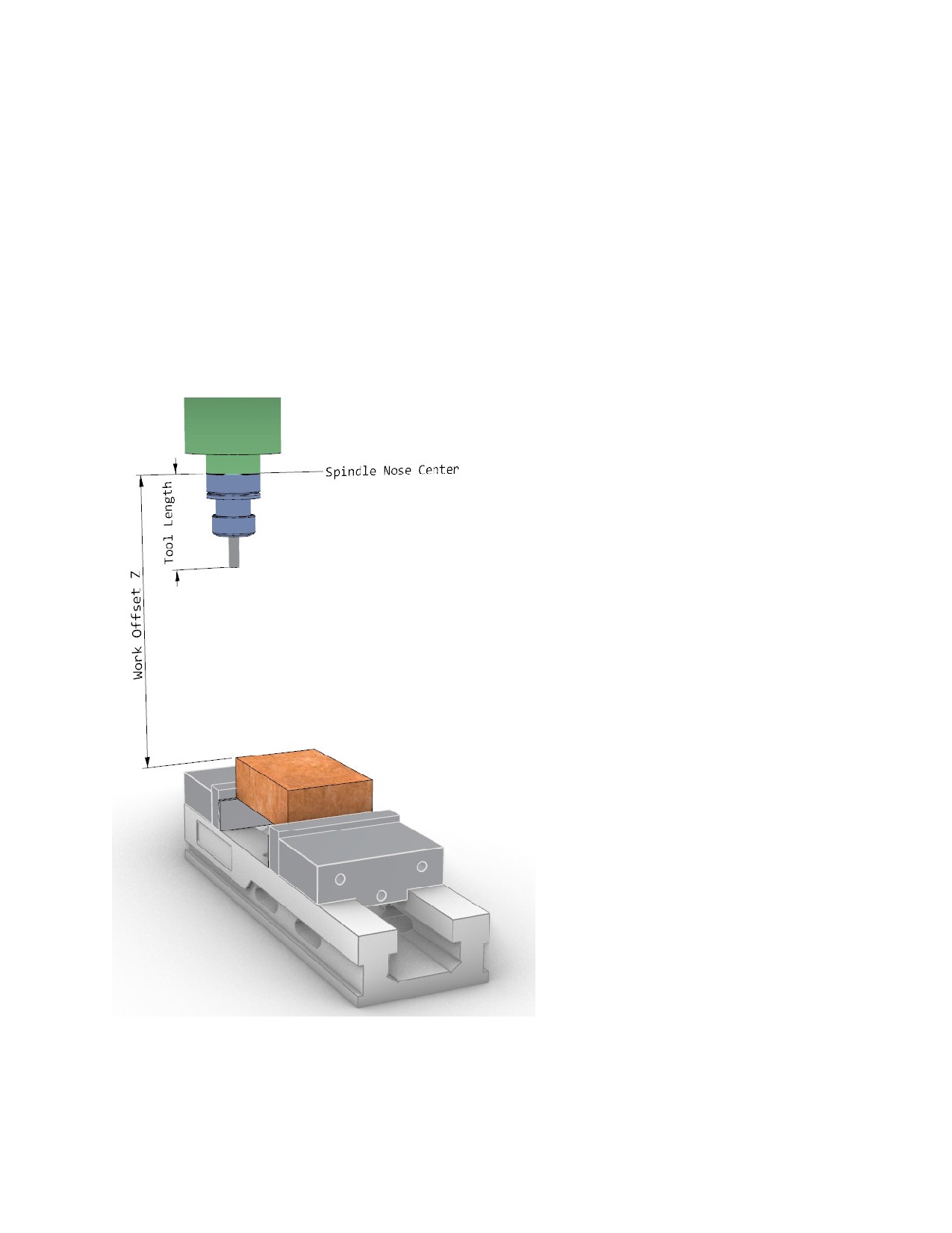
4.3.3.1 FANUC Method
The work offset is stored as the distance in
XYZ from Machine Home (G53) to the
spindle nose, centered on the offset
location.
The Tool Length Offset (Hnn) is stored as
the distance from the spindle nose to the
tool tip. We use a height gauge to measure
this length of each tool on a surface plate
and manually input it to the control.
Using this method you never actually need
to drive the spindle nose to the location to
find a work offset. It’s possible to find any
new work offset by driving the tool tip
down, then subtracting the tool length
from the measurement.
The Z component of the work offset will
be a rather large negative number, and the
tool length will be a positive number.
When the two are added together we get a
negative number that is closer to zero than
the Z work offset alone.
12
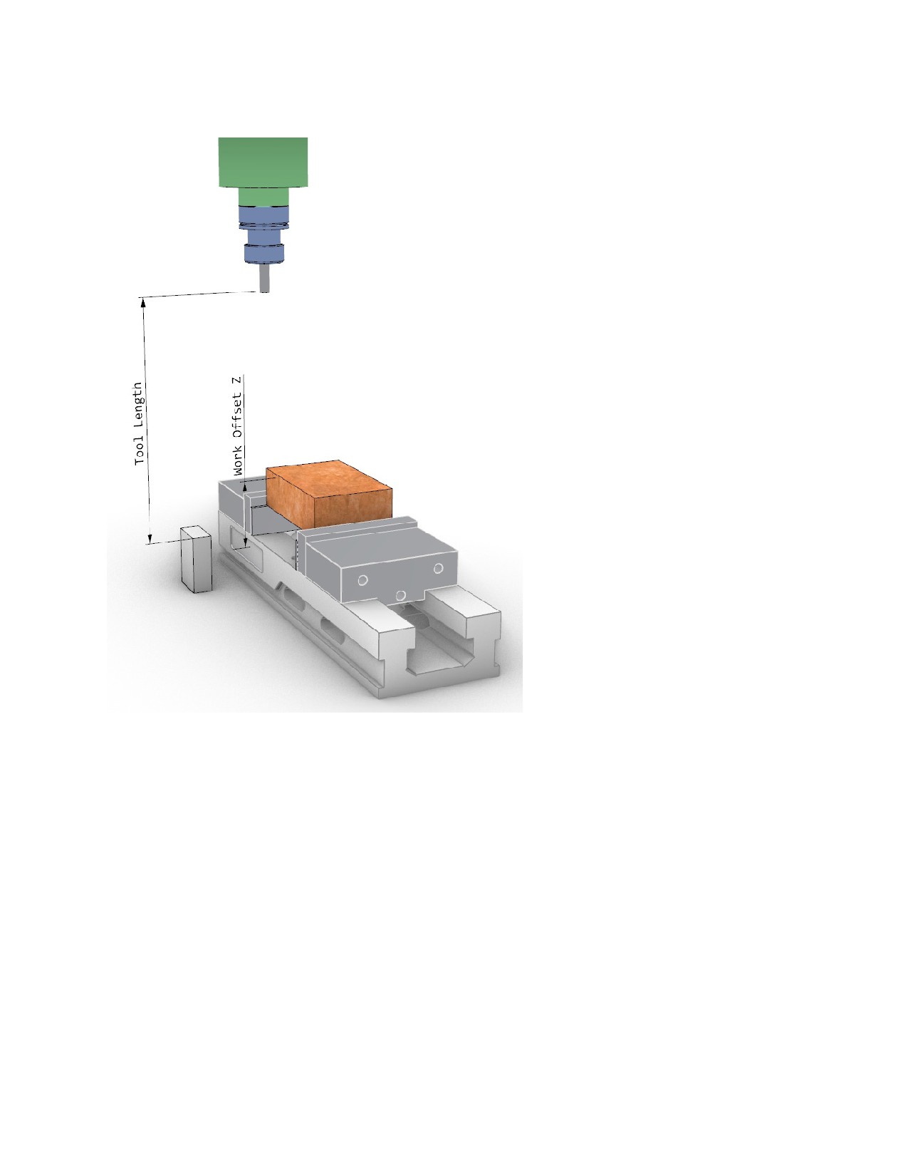
4.3.3.2 HAAS Method
Each Tool Offset is stored as the
distance from Machine Home (G53) to a
known location. In dFab we use the 3 in
side of a 123 block off the table.
To find the work offset, we make a
relative measurement with any tool from
the 123 block to the work offset and
enter that for the Z component in the
work offset.
If the tool is long we will have a smaller
negative number and if the tool is short
we will have a larger negative number as
the tool offset.
The work offset will always be the
distance in Z from the top of the 123
block to wherever your Work Zero is
located on your material.
4.3.4 Offset Safety
When we make measurements on the machine, we NEVER actually move the machine to touch our stock.
We always drive the machine close and use a 123 block, a precision ground piece of steel that has the
dimensions 1”x2”x3”, to gauge the distance.
When adjusting the tool height, move the 123 block off to the side, then once the adjustment has been made
slide the block to check. Do not force the block under the tool, move it slowly and feel for any contact. If
there is contact, raise the tool by 0.001” and try again. This is a very fast and safe method of verifying the Z
components of our work and tool offset. The control is capable of addition and subtraction so we can just
subtract 1” from our measurement and move right along.
13
5 CNC Tooling for Wood, Primarily
Because it is so much more affordable and forgiving, our conversation about tooling will be focused on wood
cutting tools. Where applicable there are some parameters and information below that applies to metal cutting
tooling as well.
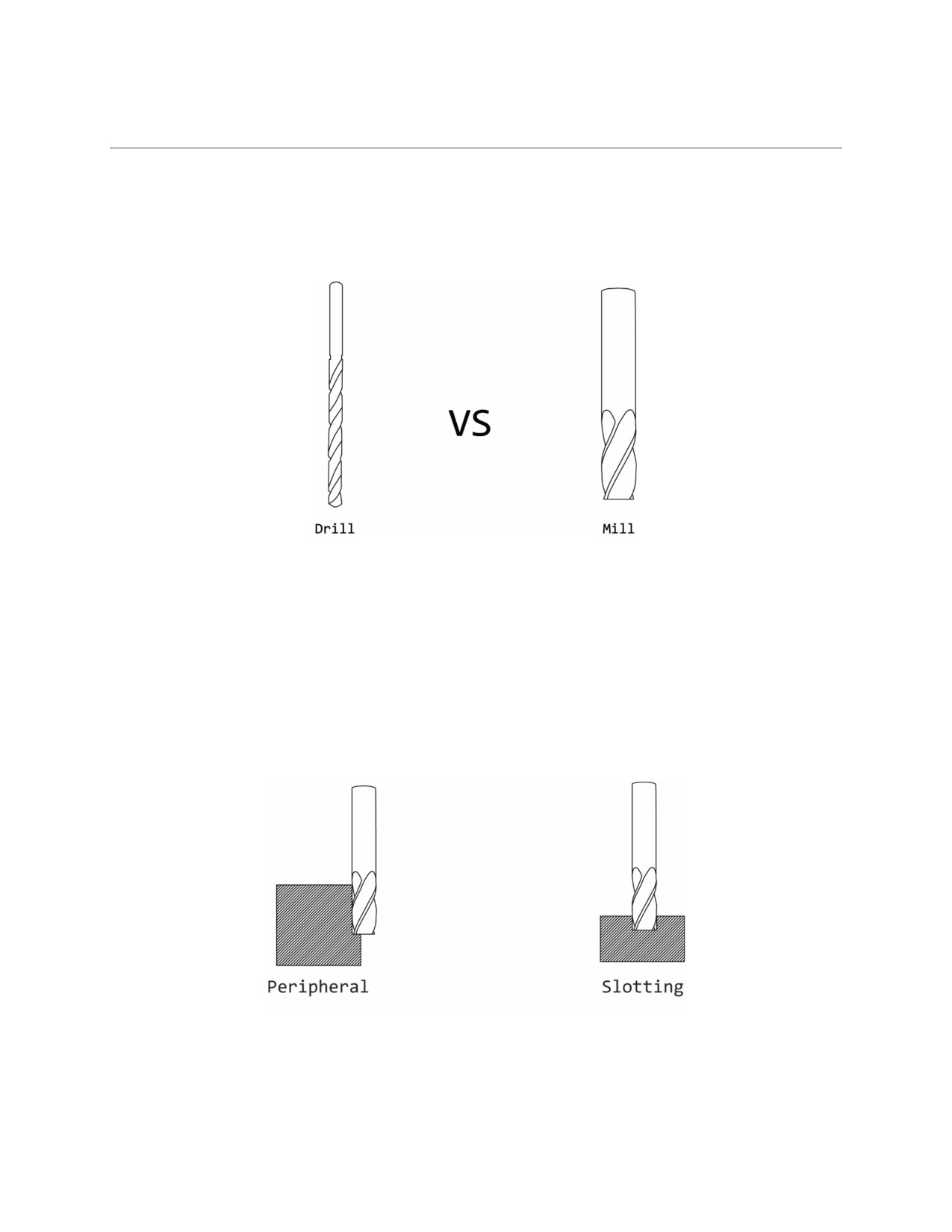
5.1 Drill vs. Mill
Drill bits intended to cut along the axis of rotation (axial engagement) as when plunging, or stepping down
into the material. The flutes are not sharpened and are intended only to remove chips. Drills are not effective
at cutting when moved sideways in the cut.
Mills are most effective at cutting when stepping over along the radius as the tool rotates (radial engagement),
some mills cannot plunge, and can only cut when the side of the tool is engaged with the material.
5.2 Tool Load
When we engage the tool with the material it moves along its radius as it cuts. Here we are imagining a
section cut of side view of the tool as it cuts through the material.
5.2.1 Peripheral
Whenever possible, axial depth of cut is maximized, this maximizes usage of the sharpened flutes. We need to
leave space for the chips to go, and don’t want to overstress the tool causing breakage, so radial engagement
is low. This strategy is used for finishing operations in pockets, or when removing a small amount of material
14
around the perimeter of a shape to achieve final dimension. Tools cannot cut deeper than their flute length
when peripheral milling, this is sometimes referred to as CEL or cutting edge length.
5.2.2 Slotting
When cutting parts that are nested on a plywood sheet in dFab we must engage 100% of the tool diameter
radially. As we get deeper into the slot, it becomes more difficult to get the chips out. In wood, all of our
feeds and speeds are calculated so that slots 2x diameter of the tool can be cut in a single pass. In other
words, 100% Radial Depth of cut and 200% Axial Depth of cut are standard in dFab for the tools in the
FANUC library.
5.2.3 Step Over/Step Down:
Step down is the vertical change in Z per pass also known as axial engagement.
Step over is the amount the tool engages in X and Y per pass also known as radial engagement.
5.3 Flute Type
Below are the most common flute types available for router bits along with reasons for selecting a specific
flute type.
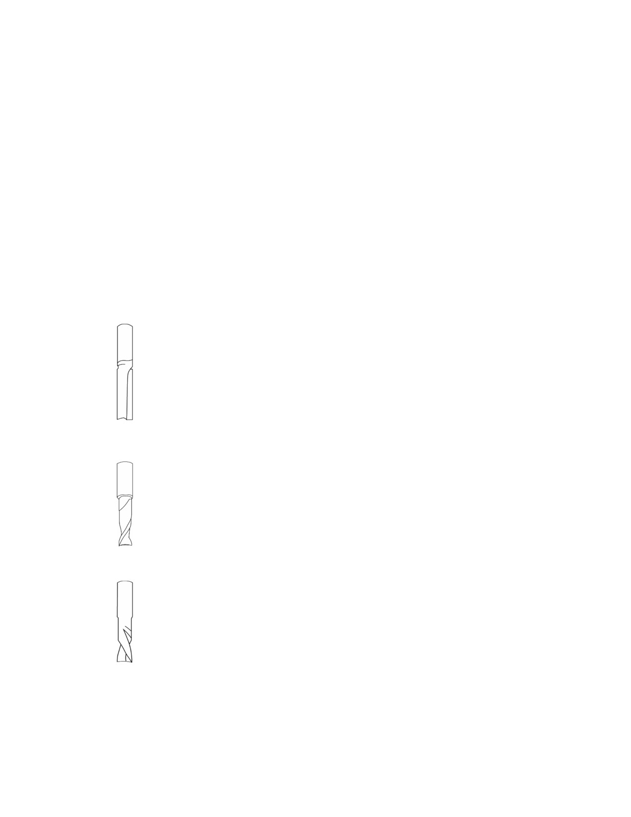
5.3.1 Straight Flute
Inexpensive tool with decent finish. Most commonly used with hand held
routers, or on router tables (not CNC). Disadvantages are lower chip loads
(longer cut times). Advantages are low cost and minimal tear out. These
tools are often made from high speed steel with brazed carbide tips. They
are intermittently in contact with the part, whacking it each time a flute
comes around.
5.3.2 Up Spiral
Because of the excellent upward chip evacuation and low cost, these tools
are used for roughing operations where high removal rates are prioritized
over a perfect finish on top of the part. These tools are capable of cutting
deeper and faster than their straight flute counterparts, however they often
tear out on the top of the cut due to the upward sheering motion. Because
of the spiral, the flutes are in constant contact with the part.
5.3.3 Down Spiral
These tools have a sheering spiral that rotates in the opposite direction
from the up spiral, pressing the chips down. The advantage is a clean finish
on the top of your part, no tear out! The disadvantage is terrible chip
evacuation which translates to shallow depth of cut, using many passes to
reach the desired depth. Use in shallow pockets less than ~0.200 inches.
15
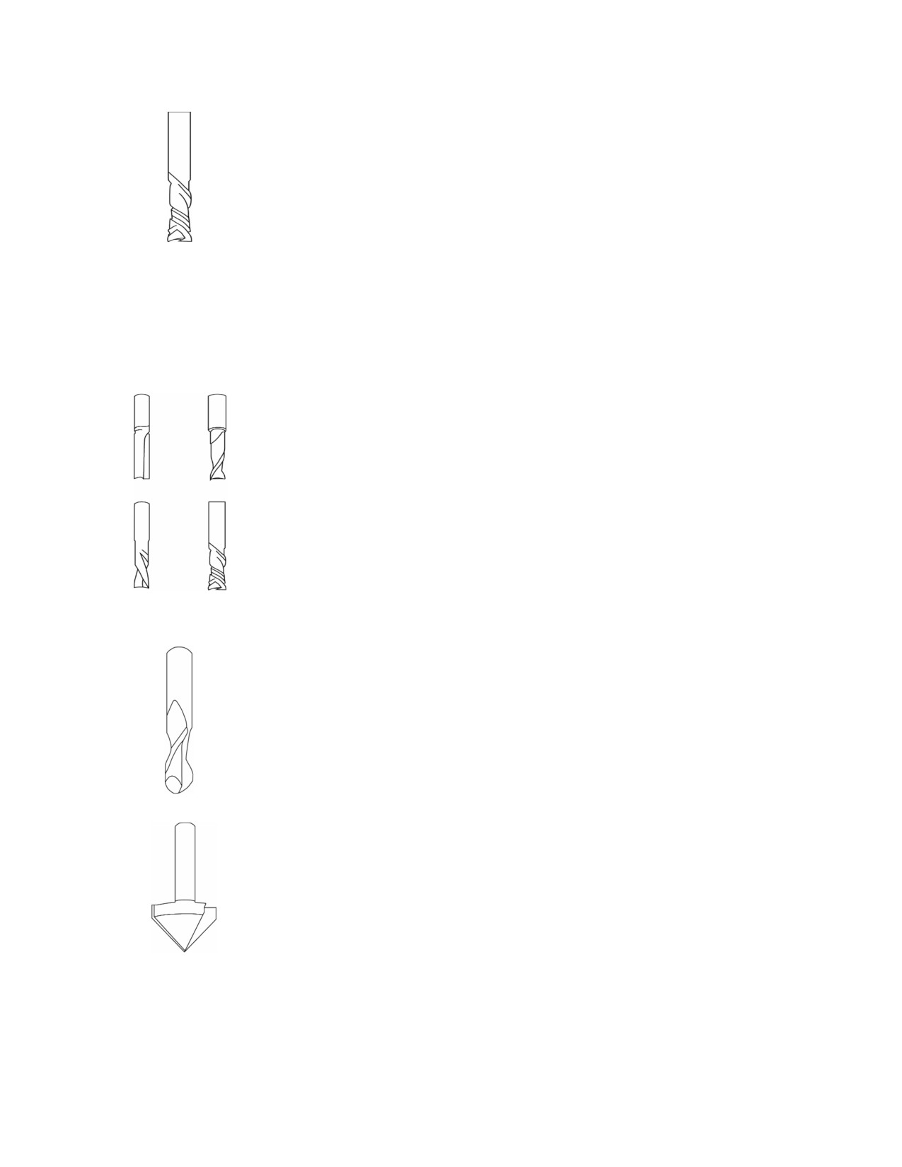
5.3.4 Compression
Most expensive grind on a solid carbide tool, these combine both up and
down spiral into one tool. There is up spiral on the bottom ~0.200 inches
and down spiral on the rest of the tool. These are great for achieving high
feed rates and perfect surface finish on top and bottom plywood, melamine,
particle board, and other engineered woods- producing a good finish on
solid woods too.
5.4 Tool Profile
Descriptions and uses of common tool profiles used when machining 2.5d features in wood on a CNC
router.
5.4.1 End Mill
This is the most common and versatile tool profile. All of the examples so
far have been end mills. These are capable of machining a flat floor and
vertical walls. They have a negligible corner radius, leaving a sharp inside
corner on a pocket when viewed as a section from the front or side. We
use these tools primarily for joinery and cutting parts from a nested sheet.
Due to sharp corners, these tools do not have as long of a lifespan as a
tool with a small radius. These are sometimes offered with 0.005”-0.05”
radius for longer tool life, we use these radius end mills for steel on the
Haas.
5.4.2 Ball Mill
The radius of this style mill when viewed from the side is equal to the
radius of the tool from the top. These are primarily used for 3D machining
operations because they will produce less error in matching an undulating
surface as they follow the toolpath than an end mill. They are also good
for use in pockets when strength is prioritized such as when making
enclosures. The radius edge eliminates tear out when the tool is engaged
axially less than the radius.
5.4.3 V - Mill
These come in a variety of angles, measured as the included angle, so a 45
degree chamfer would be a 90 degree V-Mill. Primary uses include
chamfering edges, engraving, and lettering.
5.5 Tool Holders
Tool Holders allow for the use of an automatic tool changer, tools can be pre-loaded with offsets stored on
the control. This makes for easy and accurate use of a variety of tools in one file. These are held into the
spindle taper with a draw bar which pulls on either a pull stud or on a race inside the cone of the holder.
16
5.5.1 Tool Holder Types
In dFab we use CAT 40 tool holders on the HAAS and HSK63-F holders on the FANUC.
5.5.2 ER Collet System and How to Assemble
The collet holds the tool into the tool holder, and it is tightened with a collet nut. The first step after selecting
the correct size collet is to snap the nut onto the collet. Next insert that assembly into the tool holder and
finally put the tool into the holder. Be sure not to insert the tool such that the flutes go inside the collet. Also
be sure that the shank of the tool is held by at least ¾ of the length of the collet.
5.6 Feeds and Speeds
These attributes are associated with each tool in the tool library and will be automatically selected. These are
essential concepts, and should you begin to use tooling outside of the tool library or want to work with the
Haas you will need to know this content.
There are two key factors in determining a starting Spindle Speed and Feed Rate for your material and cutting
tool. While the Spindle Speed and Feed Rate are what we actually use in the CNC program, they are
determined from a recommended Cutting Speed in Surface Feet per Minute (SFM) and Chip Load and then
tweaked and perfected through experimentation and experience. There are numerous factors that could
influence your Feed Rate and Spindle Speed and much more information can be found on this subject in
Machinery’s Handbook.
5.6.1.1
Determining Spindle Speed:
The cutting speed, in combination with the tool diameter are used to determine spindle speed. The
cutting speed (SFM) is the linear velocity with which the cutting edge or tooth of your tool moves through
the material to be cut. It is important to note that cutting speed is different than feed rate. In the case of a
milling machine or CNC router, cutting speed is the speed at the cutting edge of a tool in relation to the
material, whereas the feed rate is the speed of the entire cutter in relation to the material. Cutting speed will
allow us to determine spindle speed.
To understand the relationship between cutting speed (SFM) and spindle speed (RPM), imagine a lathe where
the part spins and the cutting tool is stationary. On that lathe there is a round piece with a radius of 1 foot.
The distance that part would travel per revolution would be 2*pi*r or about 6 feet. If that part were rotating
once per min (a spindle speed of 1 rpm), the Cutting Speed at the perimeter would be 6 feet per min or 6
SFM. Notice how the units work too. The circumference of the circle is in feet per revolution or (feet/rev)
and we are multiplying that by revolutions per min (rev/min), the revolutions cancel and we end up with
(feet/min). We typically measure cutting tools in inches so the formula becomes:
V = (pi * D * S) / 12
Where V is the cutting speed in feet per min (SFM), D is the diameter of the cutting tool in inches and S
is the spindle speed in revolutions per minute. It’s helpful to solve for spindle speed because the cutting
speed and tool diameter are known.
S = (12 * V)/(pi * D)
Cutting speed can be lowered to meet your needs, but exceed the given limits for your tool material and part
material and you will damage tooling and have poor part finish.
17
5.6.1.2
Determining Feed Rate:
Chip load in combination with the spindle speed, calculated above, and the number of teeth on your cutting
tool will determine your feed rate. Chip load, also called feed per tooth, is the thickness in inches of a little
shaving or chip generated by your cutting tool while making a cut. This could also be described as inches per
revolution in the case of a single flute tool, or the advancement per tooth if there are more than one flute.
Chips can be measured if you are cutting plastic or metal, but wood chips tend to break when cut and are
unreliable indicators of chip load. The formula for chip load is below:
f = F / (S * n)
Where f is chip load (inches), F is the feed rate in (inches/min), S is spindle speed (rev/min) and n is
number of teeth. If we solve this for feed rate we get:
F = f * n * S
5.6.1.3
Dialing It In:
The above calculations are a great way to get started, but realistically cutting conditions vary extensively and
can be dialed in for your exact purposes. This can be time consuming for prototyping, so use safe speeds and
feeds to get your part done slowly successfully the first try.
If you are making a long cut or doing a small production run, you’ll want to really dial it in. Start out with the
low end recommendations or your best guess, increase your surface speed within the recommended range for
your tool and material until the part finish starts to decrease. Back off a little bit, then increase your chip load
until part finish starts to decrease.
Tools are designed to handle a specific chip load, and you’ll want to keep them at that chip load if possible.
Reducing the chip load within reason can be good for your cut quality and easier on your setup, however
going too far can make the tool perform very poorly, causing a ton of heat to damage the tool. ¼ inch and
larger tools need 0.001” feed per tooth at minimum.
Keep in mind that even if you have theoretically perfect feeds and speeds, you can still have terrible part
finish or break tools if you are not able to get the chips out of the cut or if your part is not securely held or if
your machine is not rigid enough to take the cut. If your part is moving around, or if you are suspicious that
your part is moving, try reducing the axial load, or try reducing the chip load (feed per tooth), or try
increasing the spindle speed. If you have no idea what to use for some random no-name brand carbide tool,
start here: Chipload: 0.001 to 0.003” SFM: 1000 (wood or plastic), 600 (rigid insulation foam), 80 (steel), 500
(aluminum)
5.7 Work Holding
The part to be machined can be held by various means. Two common methods a vice, or by vacuum. When
using a vacuum, a large vacuum pump is connected to the machine that is gated with valves at the front of the
machine which can be opened or closed to direct the vacuum under your part. The vacuum can be further
directed by use of rubber plugs. Gasket is used to prevent air from leaking in around the sides. To provide a
sacrificial surface so we can cut through our part, we typically use MDF as a spoilboard. This piece of
material holds the vacuum and transfers that holding force to our part. Our vacuum pulls 13” of mercury,
which is under power for a production setting, but still pretty awesome. Using vacuum we can hold parts
around 12” by 12”, smaller parts will require tabs to hold them to the larger sheet, or screws. If you use
screws, you must model them into your stock and be sure not to hit one with the tool.
18
6 Create a CAM File
CAM (Computer Aided Manufacturing) software is used to create toolpaths from CAD (Computer Aided
Design) geometry. In dFab, our workflow is Rhinoceros 3d (CAD) to RhinoCAM (CAM) or Fusion 360 to
HSMworks which is built into Fusion360 in the “Manufacture” workspace.
This software is beyond the scope of this manual and is only taught through coursework. Your faculty will
review your file with you before they oversee your operation of any dFab CNC equipment. After you and
your faculty are confident with the file, you may schedule time on the machine with the dFab studio manager.
Do not purchase material prior to the review with your faculty, often design changes are made at this time
that result in a change of material thickness or type.
A good overview of this process has been created by Autodesk and can be found under
Choose manufacture on the left under the Learning header.
Below are important steps in creating a good CAM file.
6.1 Drawing
Your model is the foundation on which everything else is built. You will want to be sure that it is precise.
Often you will need to model in fixtures or stock. These will help the software determine areas to avoid or to
cut.
You do not need to be great at 3d modeling to use CNC, but you do need to be precise and you absolutely
need to be able to think through what the machine will do when cutting your file.
If you just need a couple simple shapes cut out and you can draw them in 2d but do all the 3d planning by
other physical means, go right ahead and do it that way. Too often students let this stuff get way more
complicated than it needs to be. It’s perfectly ok and often advisable to plan your project using methods that
are familiar to you, then draw only the shapes you need before planning your CAM file.
Use the laser cutter or 3d printer to prove concepts or prove your drawing. These methods are incredibly fast
and inexpensive. You will save so much time learning about some small flaw in your file by prototyping with
either of these tools first, and you’ll have some cool models or prototypes to hang on the wall!
6.2 Reserved Work Offsets for FANUC in dFab
We have reserved work zeros in dFab. They are listed here as a reference.
G54 - The top, near, left corner of the spoilboard when it is pressed against the popup pins. This would be
the near left corner of your stock at the bottom. When setting your work zero you must place it at the
corner of your stock that has the lowest value for XY and Z. Maximum depth when cutting on the
spoilboard is G54 Z-0.010, this would be a break through amount of 0.010 inches.
G55 - The near, left top corner of the table. This is used often when cutting solid wood stock to get better
vacuum. Maximum depth when cutting directly on the table is G55 Z0.100, do not ever cut through.
19
G56 - The near, left, top corner of the 30” by 60” spoilboard when it is centered on the mark on the table.
This would be the near left corner of your stock at the bottom. When setting your work zero you must
place it at the corner of your stock that has the lowest value for XY and Z. Maximum depth when
cutting on the spoilboard is G54 Z-0.010.
G57 -May be reserved on whiteboard check with studio manager, erase when you’re done
G58 -May be reserved on whiteboard check with studio manager, erase when you’re done
G59 -May be reserved on whiteboard check with studio manager, erase when you’re done
6.3 Toolpath Basics
Do not include any extra geometry in the file, it can make setting the stock and clearance plane difficult.
Input geometry is critical. Simple mistakes such as drawing your input curve at the wrong z height will
crash machine. Always use the shortest tool with largest diameter possible.
6.3.1 Stock Setup
Measure your actual stock after you have purchased it with a ruler to the nearest 1/8 inch for X and Y
dimensions, and nearest 0.005 to 0.01” for the Z dimension. Take measurements from all 4 corners for Z
measurement. Don’t forget to adjust your stock in your file and double check the work zero location after the
adjustment.
Extruded Stock: stored in file as “Regions Stock” (RhinoCAM)
Disadvantage - Only extrusions can be defined
Advantage - No separate layer needed, very easy to use,
Recommended to primarily use this form of stock definition whenever possible
From Selection: stored in file as “Regions Stock” (RhinoCAM)
Disadvantage - when hidden then shown after programming, your toolpaths will be affected because
rhino will think you have added new control geometry.
Advantage - Any stock shape can be defined
When using Stock from Selection, put it on a separate layer
6.3.2 Toolpath Types
Do not cut deeper than the CEL (cutting edge length or flute length) and do not break through (cut into the
spoilboard) more than 0.010 inches.
Profile: Intended for cutting shapes from a larger sheet, or carefully finishing a shape to final dimensions.
The cutting tool follows the edge of your control curve or input curve, the centerline of the cut will
be offset by the radius of the tool.
The feeds and speeds used in dFab are such that any tool can cut two times its diameter in wood, and
foam, up to 1x in plastic and ½ its diameter in aluminum or steel in a profiling pass (full width cut)
Pocket: Intended for rough clearing of all material inside of, and up to a control curve or input curve and
down to a single depth. Pockets may go partially through or all the way through your material.
Pockets can be set up to include a finish pass where the tool will cut the walls to size, though best
practice is to follow a pocket with a profiling pass to cut walls to specification. Pockets are used in
place of profiles when small scraps would be sucked off the table and into the dust collection system.
20
The feeds and speeds used in dFab are such that any tool can cut two times its diameter in wood, and
plastic aluminum or steel with appropriate step over being 10-25% of the tool diameter. Careful
attention must be paid to entry and exit. 1-2 degree helical entry on metals, plastics are 2-5 degrees
and woods or foam is 10 degrees. Watch out for areas where the tool would be slot cutting (not
actually stepping over at the prescribed 10-25%).
Facing: Intended to remove material from the top of stock to bring it to dimension in the Z axis. The center
of the tool cuts up to the line ensuring that the entire part has been cut to the depth specified. Step
over is 25% to 95% with step down being 0.005 to 0.100 inches.
Drill: Intended to engage a tool along its axis to make a round hole. Drills can only go three times their
diameter before we must back the drill out of the hole to clear chips. This process is called pecking.
6.3.3 Entry and Exit
Because end mills are designed to cut radially and not axially (move laterally but not plunge) one of the most
important considerations are how the tool enters the material. RhinoCAM has funny names for these, which
are listed in parentheses below.
Plunge (None) - Tool moves straight down at the programmed plunge feed rate. Plunging implies that there
was no hole drilled prior to engaging the tool with the material, it’s functioning like a drill. This is the
least desirable way to enter a cut.
Ramp (Along Path) - Tool moves along the Z axis while also moving in X and Y to “ramp” down to the
cutting depth. This is the easiest to program and much easier on the tooling than plunging. Use this
for nested sheet cutting or when entering pockets. The path angle must be less than 10 degrees for
wood, and in plastics or aluminum between 2-5 degrees. For steel 1 degree to 3 degrees. The height
of a ramp must be the depth of cut or a little more or the tool will still be plunging.
Pre-defined positions (None) - if prior to plunging a drilling operation is used, the tool can start in that
hole created by the drill. This is the most efficient way to go, but tedious. Generally this would be
used for a production situation in a machine with extra tool holders.
Leads (Lines and Arcs)- These are arc or straight line moves that start off the side of the part or in
previously cut material then engage the uncut material radially. They are used on finishing passes for
pockets, or when access to the outside of the part is easy. These leave a better surface finish than a
ramp.
6.4 Simulation
Both RhinoCAM and Fusion360/Inventor HSM have robust simulation capabilities. You must use the
simulation to check for and verify that there are no collisions.
Both softwares will display red for collisions in the solid simulation model and have the capability alert the
operator of any collisions.
Ask your instructor to show you how to check for collisions, this is especially true when cutting deeper than 1
an inch or when doing any 3d machining.
6.5 Checking gCode
After posting your gcode, review the text file to ensure that you got what you expected.
21
Notepad++ is the recommended software for this procedure. You can set up a user defined language which
will make viewing gCode much easier.
Go to Language=> Define Your Language… choose Import… and navigate to this folder on the server
\\picasso\Courses\_Student Resources\dFab\Resources\Notepad++ Language
Choose the gCode.xml file. Save and restart Notepad++
You will now see gCode as a language choice at the bottom of the Language Menu
6.5.1 File Name and Post Processor
Your file name will be posted as the first comment in the file, double check that this is on line 3
Directly below the file name, the next comment is which post processor you used. Double check that it is the
dFab FANUC post, or the post for the machine that you are using. All dFab posts will say dFab and the
name of the machine, also below this will be the name of the last person to edit the post and the date it was
last edited.
6.5.2 Work Offset
The default work offset, G54, from RhinoCAM appears on line 13, just before the tool list. If you used
another work offset, look for it after the tool list.
In Fusion the first toolpath will be commented with whatever its name was in your setup. The work offset
will be the first line below that comment probably on line 19. Our post is set up to use the actual offset
number, so do not follow directions from Autodesk on this one, if for example you use 1, it will not post
G54, it would post G1.
6.5.3 Stock Length Z
This line will look something like #1=0.7000 for 0.70 inch plywood. It will be located on line 21 or 22 and
must be the distance in Z from your work zero to the top of your stock.
The machine will stop and prompt the user to check the tool length. The number stored in #1 will be added
to 3” on a line that looks like this:
/ G43 H11 Z[#1+3.0]
This code makes it possible to have the work zero set to the bottom of the stock and check your work offset,
tool offset and stock thickness in one step.
If you are using offsets G57-G59 and your work zero is set to the top of your stock, then change this to
#1=0.00
6.5.4 Max Tool Depth and Break Through
Our standard work offsets (G54 and G55) are at the bottom of your stock (the top of the spoil board) and
the standard break through amount is 0.010” so the max tool depth is usually Z-0.0100 inches
In code posted from RhinoCAM use ctrl+F to find all negative z moves. This would be done by searching
for “z-.” Searching for this will allow you to find each instance where the tool goes negative, it’s far safer than
searching for z-0.010 because in this second case the tool could be cutting to z-0.100 and you would not see
that in your results.
22
In code posted from Fusion360 or Inventor HSM the ZMIN values will be displayed in the tool list and as
the first comment after each tool change.
6.6 Save a Program on the Network Drive
The root of the network drive is located here:
\\picasso\Courses\_Student Resources\dFab\Shared\__FANUC__
DO NOT SAVE YOUR FILE LOOSE IN THIS DIRECTORY.
First create a folder, either in your class folder, or make a folder in “General” that is your full last name and
save your files inside that folder.
We recommend that you create a new folder in your folder for each project to contain the inevitable mess of
files for each project. So your path should look something like this:
\\picasso\Courses\_Student Resources\dFab\Shared\__Laguna__\General\MyName\MyProject
The length of your file name can be up to 32 alphanumeric characters, however the control will only preview
the last 7 digits plus the .nc file extension.
23
7 All Those Buttons!
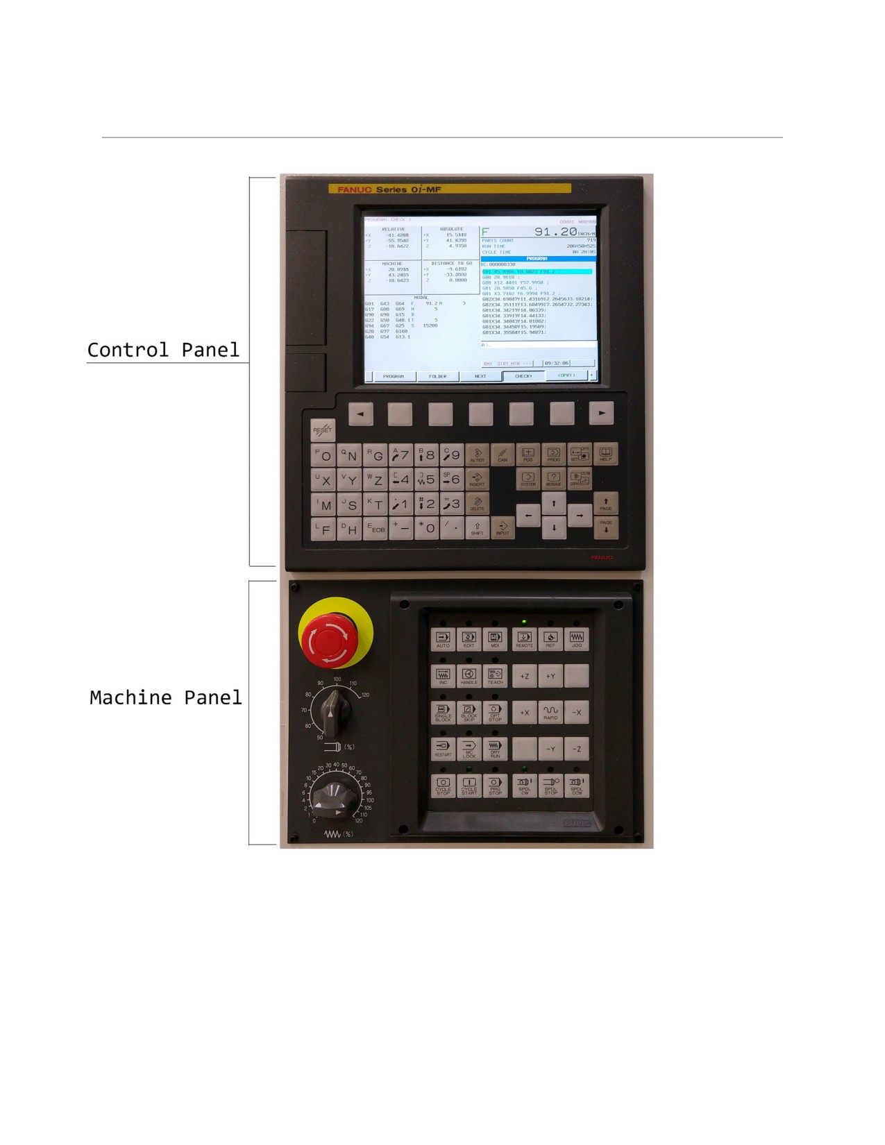
Below is a photograph of the control.
The upper panel, called the Control Panel is the brains of the operation, this is what reads the code and
handles the logic. This is built by FANUC and standard across any CNC machine with FANUC control.
Many machine tool builders choose to use this control, it is quite ubiquitous. Here you will be able to change
what is displayed on the screen and navigate to folders on the server, view your code or current position etc.
The Control panel is in charge of displays, files/directories and settings.
The lower panel, called the Machine Panel is used to control actual motion. This is where you will find the
CYCLE START button or where you would choose what Operation Mode to use such as MDI or REMOTE
or JOG. The Machine Panel is in charge of motion and modes of operation.
24
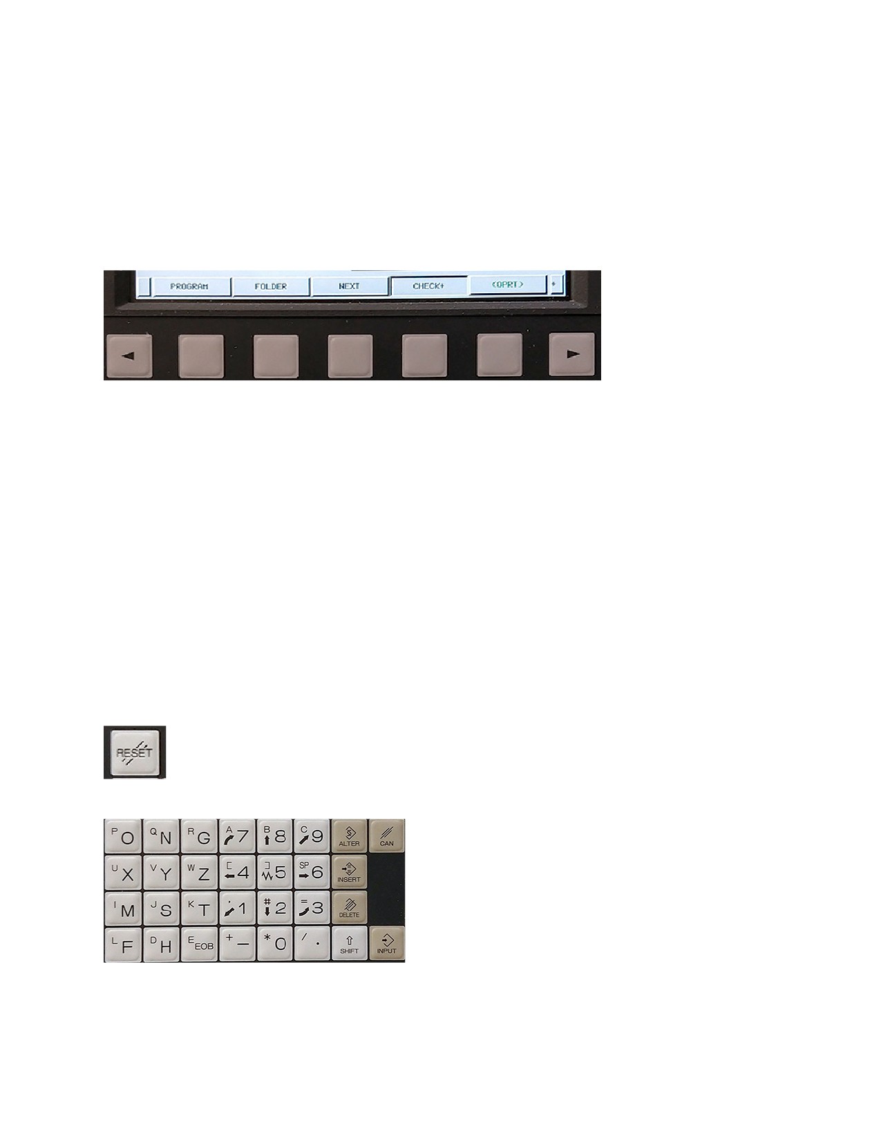
All the keys can be a little overwhelming at first. Let’s take a tour of the Control Panel followed by the
Machine Panel. You will find that it’s not as complicated as one may think after looking closely at each set of
keys and identifying their function.
7.1 Control Panel
We will go from top to bottom, left to right.
7.1.1 Soft Keys
The row of keys at the top are labeled on the screen, you activate them by pressing the button below the
label. In the image below the (CHECK) screen is active.
Notice the two arrow keys on either side? The one on the right is the (CONTINUOUS MENU) key, when a
little + sign is displayed above it the Control is telling you that there are more options available which will be
displayed above the soft keys after pressing it. This will loop around to the beginning after all the options are
displayed.
There is also an arrow on the left, this is the (RETURN MENU) key. Some soft keys, such as (OPRT),
pronounced “operate,” above will have a sub menu of soft keys associated with that choice which will be
displayed. If you want to return to the previous menu, you would press this key. It is available when a little <
character is displayed on the bottom left of the screen.
Throughout this manual we use different nomenclature for [HARD KEYS] and (SOFT KEYS). A [HARD
KEY] is a button which does not change; these keys have labels printed on them.
7.1.2 Reset
This little key is quite important. When pressed it will stop the spindle and stop motion. It will
also return the program to the top and re-set the machine to its power on state. Try not to press
this during a tool change, it will mess up some settings leaving you to wait for help.
7.1.3 ONG - Text Editing Keys
These keys are used to input information first to the input
buffer, an editing line at the bottom of the screen. The
[INPUT] key is used to copy the text from the input
buffer into the control. The most commonly used letters
are available, with the less common ones available by first
pressing the [SHIFT] key. You do not need to hold down
shift, a ^ will be displayed in the input buffer meaning
shift is active. [SHIFT] [Z] would put a W in the buffer.
[CAN] or cancel is backspace, and [DELETE] will clear the input buffer. [EOB] is a semicolon. [ALTER]
will overwrite whatever is selected and [INSERT] will put the code after the word selected by the curser.
25
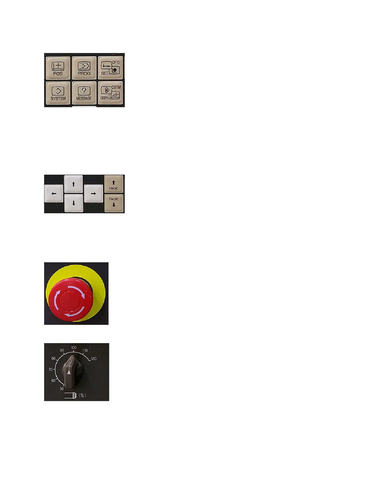
7.1.4 Display Modes
[POS] Stands for position, pressing this will display on the screen the
current position with the soft keys offering different coordinate systems.
Relative, Absolute, Machine, or Distance To Go.
[PROG] stands for program. This will display the active program. We always
run from the (CHECK) screen within program which also displays all
coordinate systems as well as the active G and M codes.
[OFS/SET] This key is referred to as offsets. It is where you can store work offsets and tool length offsets.
[MESSAGE] is the key which will display the alarm screen or the operator message screen. Some dFab code
activates this screen to display a message. To return the screen to display the program you are running you
would need to hit the program key.
7.1.5 Navigation
This functions as a regular old “d-pad” up down left right used to navigate
fields on the control. Don’t discount the [PAGE UP] / [PAGE DOWN]
buttons. They are quite efficient.
7.2 Machine Panel
We will go from top to bottom, left to right.
7.2.1 Emergency Stop (E-Stop)
This is a standard twist lock switch. It tells the control to immediately stop all
motion, including the spindle and all axis. Always depress this switch prior to
turning the main power switch on or off as a safety measure.
On the machines we have in dFab, it is always OK to press the E-Stop in the event
of emergency. However, on some machines the E-Stop will disconnect power to
the entire machine which can cause axis to drift while the spindle is winding down
before breaks are activated causing severe damage to the machine.
7.2.2 Spindle Speed Override
This knob will modify the programmed spindle speed
M3 Snnnn (spindle on clockwise, spindle speed is nnnn)
Ranging from 0.5 to 1.2 times the programed speed above, this will change the
actual spindle speed during operation. It’s really useful for dialing in speeds and
feeds for a new tool or cutting condition.
26
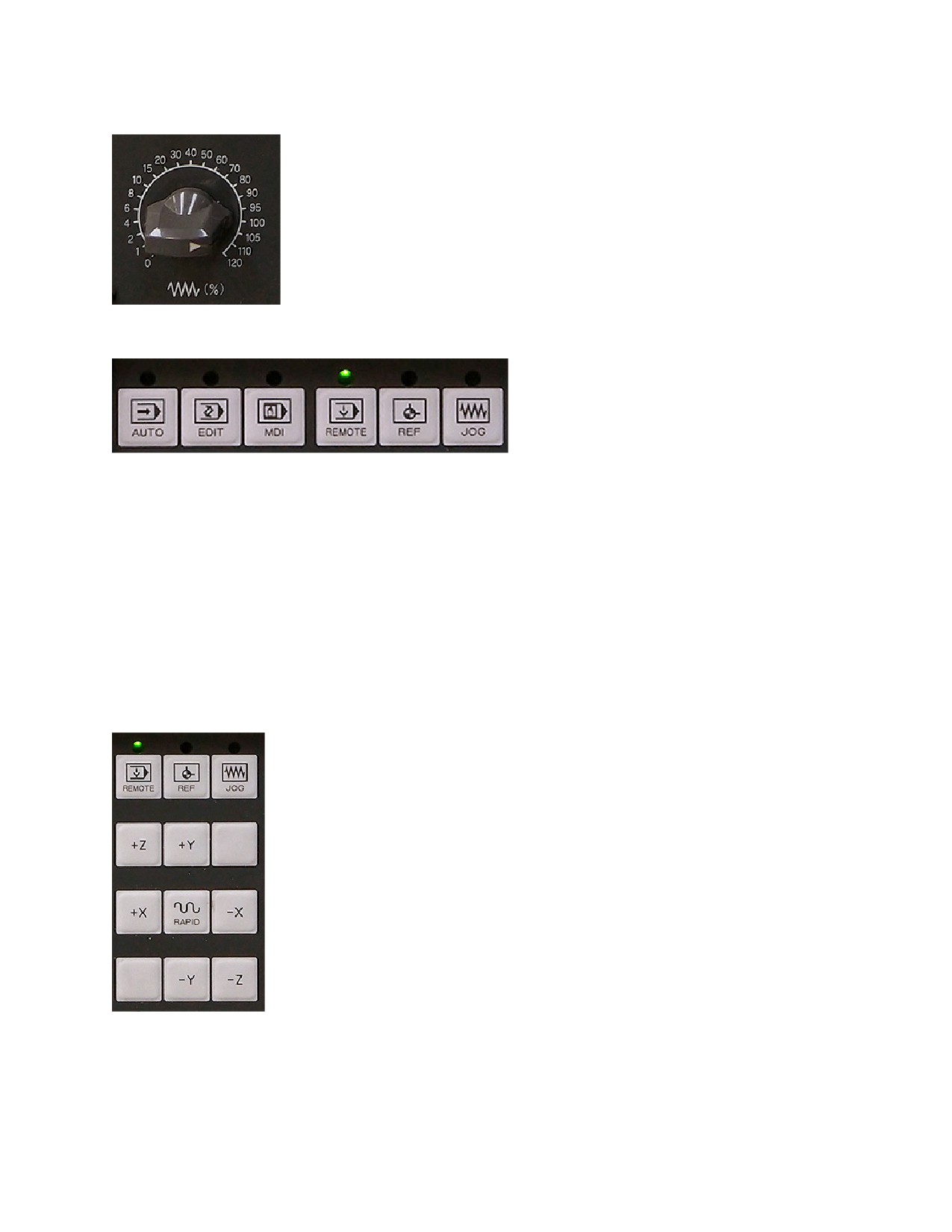
7.2.3 Feed Rate Override
This knob will modify the programmed feed rate
G01 X2.5 Y28. F200. (Make a cutting move at 200 ipm)
Ranging from 0 to 1.2 times the programmed feed above, this will change the
actual feed rate during operation. Notice that this goes all the way to 0 which is a
convenient way of stopping motion in certain circumstances. This is also quite
useful in dialing in feeds and speeds for a new tool or cutting condition.
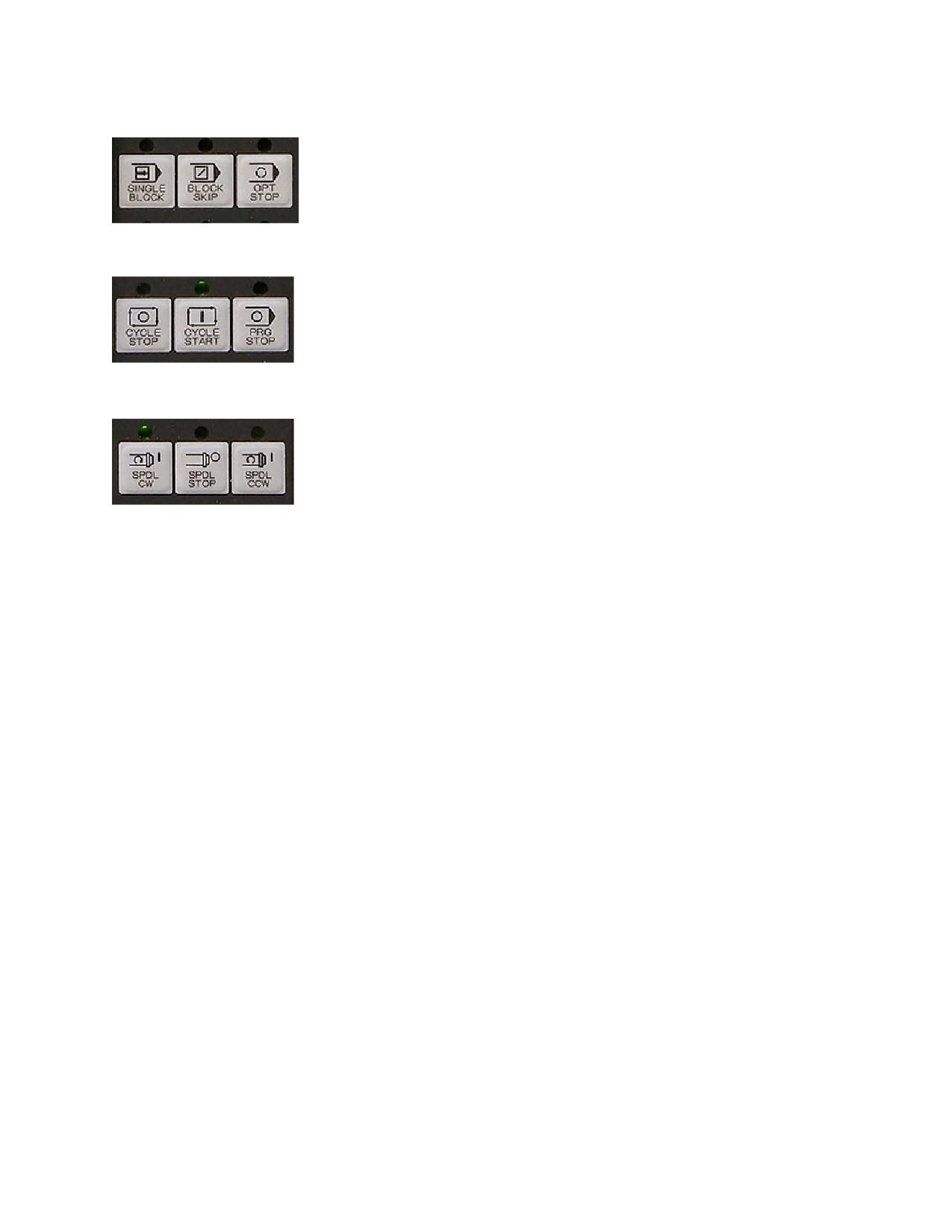
7.2.4 Operation Modes
Similar to the display modes, however these
change which input will control machine
motion. Only one switch can be active at any
time and they must be chosen correctly for the
desired function to be performed both by the
machine and on the control panel display. A light appears above the switch to show that it is active.
We only use three of these modes in dFab.
[MDI] Manual Data Input allows for gCode to be input using the Text Editing Keys to write simple programs
on the fly. This is used extensively in setup to load tools, check offsets, or drive to a specific location, it’s
faster than jogging the machine… but you’ve got to know a little gCode.
[REMOTE] mode tells the control that you want to run a file from the server. This is the mode that allows
you to run a large program like the ones you created in RhinoCAM, Fusion 360 or InventorHSM. Files are
stored centrally and are drip fed, and buffered in local memory. This process is called DNC or direct
numerical control.
[JOG] mode allows you to press and hold the marked keys below to continuously
jog in those axes. You will jog at 100ipm by pressing the key alone, and 600ipm by
holding down the directional axis key then also depressing the [RAPID] key.
When you are closer than 3 inches from the part in any direction it’s time to use the
Manual Pulse Generator (MPG) also called the Hand Wheel. This will give you
much more control.
Not pictured here, there are two selector knobs at the top, one for axis and one for
step speed with a large wheel labeled + in one direction and - in the other. Axes are
X, Y, Z and 4. Use 4 to lock off the hand wheel when passing it off or hanging it up,
that axis it is not connected. The other selector knob chooses step amount. The x10
label is 0.001” per click and x100 is 0.01” per click. There is also a x1 label, though
that level of precision is not often needed when woodworking and can be ignored.
27
7.2.5 Conditional Switches
[SINGLE BLOCK] stops the control after executing each line of code
[BLOCK SKIP] skips any line of code that starts with a / character
[OPT STOP] stops the control wherever an M01 is present in the code.
Pressing [CYCLE START] is needed to continue.
7.2.6 Motion Control Switches
[CYCLE STOP] also called Feed Hold, this will pause motion immediately
without completing the current block.
[CYCLE START] this starts the operation, or re-starts motion after M01
[PROG STOP] this will not stop motion, but will light up if the program has
been stopped by an M00 command.
7.2.7 Spindle Control Switches
[SPDL CW] turns the spindle on at the last programmed speed, can only be
used in JOG mode. Must be used to re-start the spindle if you stopped the
spindle during regular operation.
[SPDL STOP] stops the spindle, will stop the spindle while a program is
running hit [CYCLE STOP] first or you will break a tool.
[SPDL CCW] rotates the spindle the wrong way, do not use this!
28
8 Machine Operation
8.1 Power Up
Ensure that the E-Stop is depressed
Turn the switch on the machine side of the control cabinet
Wait for the display screen to show the position page,
Do not hit any buttons until you see that position screen.
Gently depress the E-stop and twist the outer ring to disengage it
8.2 Quick Review of Nomenclature
Throughout this manual we use different nomenclature for [HARD KEYS] and (SOFT KEYS). A [HARD
KEY] is a button which does not change; these keys have labels printed on them.
The CONTROL PANEL is up top with the LCD display, the MACHINE PANEL is down below with the
E-stop button.
Check out the All Those Buttons! section for a more detailed review.
8.3 Load and Run a File
You have already posted your gCode the CAM software. You verified the toolpaths through the simulation
screen, checked for collisions and reviewed both your posted gCode and toolpaths in the CAM software with
your faculty member.
8.3.1 Ensure that the control is in Embedded Ethernet Mode
MACHINE PANEL: [REMOTE]
CONTROL PANEL: [PROG] (FOLDER) (OPRT) (DEVICECHANGE) (EMBETH)
8.3.2 Load a Program from the Network Drive (Set Your File to DNC)
MACHINE PANEL: [REMOTE]
CONTROL PANEL: [PROG] (FOLDER)
Use the directional keys to navigate the folder tree to your file.
Press [INPUT] to navigate to a sub folder, use the RETURN TO UPPER FOLDER to go up a folder.
Select the file with the directional keys, files have a file extension, folders do not.
Press (DNC SET) you will see the path appear in the DNC FILE field at the top of the screen.
If you do not see (DNC SET) in the middle of the screen as a soft key, choose (OPRT) on the right, then you
will see (DNC SET).
Press [PROGRAM] (CHECK). You will now see a screen that displays position, active G and M codes, as
well as the current feed rate and your gCode (once it’s loaded, nothing will display in this field at this time)
29
8.3.3 Operator Position
While running a job, the operator will have their index and middle fingers of their right hand covering
[CYCLE START] and [CYCLE STOP] on the MACHINE PANEL.
Their left hand will be holding the FEED OVERRIDE KNOB with thumb down when the knob is at 100%.
Practice turning that knob from 100% to zero twice at this time ensuring you are able to turn that knob
quickly to zero.
Pressing [CYCLE STOP] will stop motion similar to turning the FEED OVERRIDE KNOB to zero
percent.
8.3.4 Starting Your Program
Refer to the Spindle Warmup section below if you want to warmup the spindle before running your file. The
machine will automatically run a warmup if needed when you run your file.
On the MACHINE PANEL:
Ensure that [BLOCK SKIP] is DISABLED and the light above it is NOT lit
Turn the FEED OVERRIDE KNOB to 0% and press [CYCLE START].
Your gCode will be displayed on the right side of the screen. Verify that this is the correct file by checking the
file name in the first comment.
The next two steps verify offsets and are narrated through comments in the gCode on screen. You
will be able to follow along by reading the comments highlighted in blue on the CHECK screen
when actually running your file.
8.3.5 Verify Your Work Offset in X and Y
Press [CYCLE START] and slowly turn the FEED OVERRIDE KNOB to 100%.
While the machine is moving, watch the machine in motion. Always stop motion before looking away from
the spindle.
The machine will move to the tool change position and pick up the first tool (if different than the tool in the
spindle).
The next move will be to X0 Y0 relative to your work offset (G54-59). Practice controlling the [FEED
OVERRIDE] during this move. Visualize a target location on the path of motion and practice stopping the
machine. Motion will automatically stop before any Z motion occurs at the line that says /M00 (unless
[BLOCK SKIP] is depressed).
The tool in the spindle should still be quite high above your part, but close to the Work Zero you chose in
RhinoCAM. If this looks close in X and Y, it’s safe to proceed. If not, stop and figure out where things went
wrong.
8.3.6 Verify the Z Location of Your Work Offset
Set FEED OVERRIDE KNOB to 0%
30
Ensure that the vacuum is on
Press [CYCLE START], look at the DIST TO GO values. X and Y should read 0.0000; Z should read a
negative number which is the distance between the top of your part and the tool tip plus 3 inches.
Slowly increase the FEED OVERRIDE KNOB while watching the spindle plunge toward your work piece.
Stop motion approximately 4 inches above the surface of your material. DISTANCE TO GO should read
close to -1.000 when you stop, implying that the Z axis has another 1 inch of motion left in the current move.
If you stopped 4 inches above your material and DISTANCE TO GO reads a number that is not close to
1inch, leave the FEED OVERRIDE KNOB at 0% and press [RESET] on the MACHINE PANEL, then
figure out what went wrong.
If all looks correct, you may turn the feed override back up until we complete this block of code. Motion will
stop after this block because the next block is /M00.
Follow the on screen directions to check offsets with the 123 block. The tool should be exactly 3” off the
surface of your material, and centered on the corner of your work offset. If this is the case, Congratulations!!!
You are ready to run your file. Don’t forget to remove the 123 block and turn on the dust collection.
8.3.7 Run Your File
After verifying that your work offset is correct we are ready to execute the rest of your file.
It is imperative that you carefully checked each toolpath for collisions in your CAM software’s
simulation and have not programmed any tools to cut deeper than their cutting edge length, which
is saved with each tool in our library.
Turn the FEED OVERRIDE KNOB to 100%.
With your hand ready to crank FEED OVERRIDE KNOB back to zero, press [CYCLE START] make
some chips! At the next tool change you will be prompted to check the tool length again. Follow instructions
and then press [CYCLE START] to continue.
Each time you run a new file, you must watch the entire program run and check all offsets. Stand in front of
the control, with your hand ready to stop the feed override. This is one of the best opportunities to learn
about how to program a machine, by carefully watching what you have programmed and thinking about how
you could do it better.
If anything happens which is unexpected, such as a tool cutting too deep. Turn the FEED OVERRIDE
KNOB back to 0% and press [SPINDLE STOP] or press the [RESET] button. If there is an emergency,
press the E-stop.
31
8.4 Spindle Warmup
There are bearings inside the spindle that are so precise they need to be run under no load so that they can
expand. If this step is skipped the spindle bearings will be damaged, it’s a quick 5 min cycle that runs the
spindle at 10,000 rpm, 18,000 rpm then 24,000 rpm. This is performed automatically on a tool change if the
spindle has not been used for an hour or more. Running the spindle without a tool loaded will
catastrophically damage the draw bar, which holds the tools in the spindle.
Some tools, such as T16 (Vortex 4” plainer) cannot be used for spindle warmup because it is not safe
to spin them that fast. The control checks for tool number, certain tools have been flagged as not able to run
a spindle warmup and will warn the operator. If this happens use the MDI to run a spindle warmup before
running your file by picking up tool 2. Follow the procedure below.
MACHINE PANEL: [MDI]
CONTROL PANEL:[PROG](PROGRAM) [M] [6] [T] [2] [EOB]
Verify that the input buffer looks like this:
A) M6T2;
Press [INPUT]
At the top of the screen you should now see
O0000 M6 T2;
%
Using the directional pad on the CONTROL PANEL press the up arrow to ensure that there is no code
above the displayed information.
MACHINE PANEL: press [CYCLE START]. If the compressed air is on, you will pick up tool 2 and be
prompted to run the spindle warmup. Press [CYCLE START] to continue.
You may walk away from the control while the warmup cycle runs. There is an M00 in the code at the end of
the spindle warmup to stop motion even if the warmup happens while running a file.
8.5 Store a Work Offset (M402)
Use the MDI to type in the following code
M402 Wnn; (nn is the work offset number you want to overwrite)
When you press [CYCLE START] the machine will drive to Z Home, then to X6. Y6. relative to the
currently stored offset.
It will prompt you to set the Z first. Follow the instructions in [JOG] mode, then press [CYCLE START] in
[MDI] mode to store the Z value and continue. This will store the correct Z value for Work Offset no matter
what tool you have loaded, so long as the correct tool length offset has been stored in the machine.
The machine will again drive to Z home, then to X0 and Y0. If you would like to make modifications move
the machine in [JOG] mode. Press [CYCLE START] and the XY values will be stored.
32
8.6 Jog Mode
Jog mode allows the operator to manually position the spindle. This is the simplest way to move the machine.
8.6.1 Continuous Jog
On the CONTROL PANEL press
[POS] (ALL AXIS).
On the MACHINE PANEL press [JOG].
Press and hold any of the directional keys [X] [Y] or [Z].
It is possible to jog multiple axis at one time by holding more than one key.
To jog faster hold down the [RAPID] key after depressing the directional key.
On this machine X+ and X- behave backward of what you would expect by the locations of the buttons on
the panel.
8.6.2 Handle Jog
On the CONTROL PANEL press
[POS] (ALL AXIS).
On the MACHINE PANEL press [JOG].
Pick up the MPG or Handle Jog wheel.
Using the selector knobs choose the axis and step amount. x10 is 0.001” per click and x100 is 0.01” per click
Use the wheel to jog around with more control
Set the Axis Selector back to “4” before hanging up or handing off to prevent accidental motion.
8.7 Some Common Mistakes
While possible to fix some common mistakes by editing the gCode directly, please do not do so. Often you
will need to make another change in the file later on and can easily forget that you edited the gCode. The
preferred procedure is to change the RhinoCAM file each time you make a change and re-post.
8.7.1 Forgot the Vacuum
If the 123 block does not fit between the tool and your part, it’s likely you forgot the vacuum, turn it on and
try again
8.7.2 Measured Incorrectly
Its probably not the tool offset or the work offset, double check your material thickness with calipers.
8.7.3 Set work zero to top of stock, set work offset to bottom of stock
Be meticulous and avoid distractions when setting your work zero in your CAM file and your work offset on
the machine. Be sure it’s correct, this is the most common mistake for beginners and experts alike. It’s really
easy to screw this up. Always double check these when you set them, luckily while you are at MICA the code
will prompt you to check this.
8.8 Clean Up
After the file completes running, you will get out the vacuum and clean up all the dust after removing your
part from the vacuum table. On a short production run, don’t bother to clean anything else until you’re done.
After you’re completely done, use handle jog or the MDI to move the machine around and vacuum up any
33
areas you can’t reach including the floor. If you had [BLOCK SKIP] active the tool will be left in the spindle.
Please do not leave any tools in the spindle overnight.
M6T0;
Never use compressed air near the spindle!!! You will damage or destroy the spindle.
Be careful not to press the green tool release button while vacuuming!
9 Advanced Machine Operation
9.1 Stop and Jog Away, Return and Continue Cutting
9.1.1 Stop Motion and Spindle
MACHINE PANEL: [CYCLE STOP] [SPINDLE STOP]
You can walk away from the machine at this time.
9.1.2 Jog Away
CONTROL PANEL: [POS] (RELITIVE) or [POS] (ALL)
AXIS LETTER [X Y OR Z],
You will see that letter in the input buffer and the correlating axis letter start to blink.
(ORIGIN) (EXEC).
The RELITIVE display will read 0.000
MACHINE PANEL: [JOG]
Go ahead and jog around, before starting your file again, jog back to where the RELATIVE display reads 0
on all axes.
9.1.3 Continue File after Stopping Spindle
MACHINE PANEL: [JOG] [SPDL CW] [REMOTE]
Wait for spindle to get to speed
[CYCLE START]
9.2 Make a Relative Measurement
From time to time, you may need to make a measurement with the machine. This is possible by first zeroing
the desired axis in the RELITIVE position screen (on some machines called OPPERATOR), then by driving
to the other location and reading that same RELITIVE position.
CONTROL PANEL: [POS] (RELITIVE)
MACHINE PANEL: [JOG] then jog to first position. Do this carefully, always use a 123 block or some other
method to keep the tool and spindle away from your workpiece.
CONTROL PANEL: AXIS LETTER [X Y OR Z], you will see that letter in the input buffer and the
correlating axis letter start to blink. (ORIGIN) (EXEC). The RELITIVE display will read 0.000
MACHINE PANEL: [JOG] then move to the second position and read the distance.
34
9.3 Store a Tool Length Offset
Modify these only after instruction on the process. Modifying a work offset or tool length could cause a crash
leading to severe injury and/or damage to the machine.
MACHINE PANEL: [MDI] or [JOG]
CONTROL PANEL: [OFS/SET] (OFFSET)
Use the d-pad to navigate to the desired tool number in the GEOM column.
Use the text editing keys to type in the tool length as measured with the height gauge from the v-blocks to the
tool tip
[INPUT]
35
9.4 View or Modify the Values Stored in a Work Offset
Modify these only after instruction on the process. Modifying a work offset or tool length could cause a crash
leading to severe injury and/or damage to the machine.
MACHINE PANEL: [MDI] or [JOG]
CONTROL PANEL: [OFS/SET] (WORK)
Use the d-pad to navigate to the desired work offset
Make the necessary edits (+INPUT) will add to the stored value, (INPUT) will overwrite the value
9.4.1 Store a Work Offset X and Y (Edge Finder)
• Load the edge finder using the MDI and jog it close to your part
• Use the MDI to turn the spindle on at 1000rpm
• Using the x10 step on the MPG jog the edge finder until it splits at the X edge of your part.
• Stop the spindle and jog up in Z
• Zero the X axis in the relative position screen
• With the edge finder above your part, drive the spindle over 0.1” so that the center of the edge finder is
on the edge of your part, zero the relative position screen again.
• Repeat for Y axis
• Drive the X and Y axis to zero on the relative position screen, double check that the tool is centered on
the desired work zero.
• CONTROL PANEL: [OFS/SET] (WORK)
• Use the d-pad to navigate to the desired work offset
•
[X][0](MEASUR) [Y][0](MEASUR)
•
Use d-pad to highlight Y1, type the value stored for Y into the input buffer and press [INSERT]
9.4.2 Store a work Offset Z (With Tool)
• Load a tool and drive it to 1” off the top of your work zero location using the 123 block
• Don’t drive up or down with the block under the tool. Ever. Seriously don’t do it.
• CONTROL PANEL: [OFS/SET] (WORK)[Z][1.](MEASUR)
•
(OFFSET) copy the tool length stored for the tool in the spindle to the whiteboard
•
(WORK) type in the copied value with the Z field selected
•
(+INPUT) verify the math and press (EXEC)
•
Use the MDI to check your work offset and tool offset with the following code
G5n;
G00 X0Y0;
M00; (Turn feed override down, stop if the tool gets closer than 3” to material)
G43 Hnn Z(3.0+n);
36
10 Alarms and Recovery
10.1 Soft Over-Travel Alarm
Soft over-travel alarms occur when an axis has traveled beyond a coordinate limit. To clear the alarm, jog the
offending axis away (remember that the X axis jog buttons are transposed on the controller)
10.2 Hard Over-Travel Alarm
Any axis that creates a hard over-travel alarm will cause all axes to be in alarm state. This is more common
when jogging the X axis, but can happen on either end of any axis. The display will automatically go to the
ALARM screen and display an entire page of red error messages for all axes at once.
You must jog the offending axis off the switch before the alarm can be cleared.
Bypass the alarm state by pressing [RESET] while holding down the left bottom [UNLABELED] button
(under [+X] and to the left of the [-Y]).
Continue holding the [UNLABELED] button and jog the over-traveled axis off the limit switch.
10.3 Paused In The Middle Of a Tool Change
WAIT - high risk of crash/causing damage or further damage GET HELP from McKibbin
10.3.1 Check that machine knows what tool is in spindle.
Check macro 510 (current tool) - McK Tool Change
[System] (PMCMNT) (DATA) - Laguna Tool Change
Highlight D0400
Press (OPRT)(ZOOM) to see data in D0400.
Verify that D0402 is set to 0 if there is no tool in spindle, or the tool number for the tool in spindle.
10.3.2 Check that the machine knows the current tool changer carousel position.
[System] (PMCMNT) (COUNTER)
Check that C0000 is set to the current tool changer position in the “current” column.
10.3.3 Check that the Rapid Traverse Rate is correct.
Parameter #1420 should read as labeled in Common Parameters section. If not it will need to be changed back
before moving forward. This would only be performed by McKibbin. Turn off the machine and lock it out
you’re done for the day.
37
38
11 Reference
11.1 I/O Channels
4 - PCMCIA (Memory Card)
17 - USB (Universal Serial Bus)
9 - EMBETH (Embedded Ethernet)
11.2 Common Parameters
Description
Parameter #
Edit Lock for O8000 and O9000
3202
Bit 0 NE8, Bit 4 NE9
Rapid Traverse Rate
1420
XY=25400.000, Z=12700.000
Stored Stroke 2
1310
1 on 0 off for EACH AXIS
Custom Macro Stop or Don’t
6000
Bit 5 SBM 1=Stop
Display System Variables
11356
Bit 4 CSD
Program Editing in word/char
3233
Bit 0
39
11.3 G Codes (Unabridged)
G00
Rapid Positioning
G01
Linear Interpolation
G02
Circle/Helical Interp CW
G03
Circle/Helical Interp CCW
G04
Dwell
G09
Exact Stop
G10
Programmable Data Input
G11
Programmable Data Input Cancel
G12
N/A
G13
N/A
G14
N/A
G15
Polar Coordinates Command Cancel
G16
Polar Coordinates Command
G17
XY plane
G18
XZ plane
G19
YZ plane
G20
Inches (G70)
G21
Metric (G71)
G22
Stored Stroke Check On (2 ONLY)
G23
Stored Stroke Check Off (2 ONLY)
G24
N/A
G25
N/A
G26
N/A
G27
Reference Position Return Check
G28
Automatic Return to Reference Position
G29
Movement from Reference Position
G30
2nd, 3rd and 4th reference pos return
G31
Skip Function
G32
N/A
G33
N/A
G34
N/A
G35
N/A
G36
N/A
G37
Automatic Tool Length Measurement
G40
Tool Radius Comp Cancel
G41
Tool Radius Comp Left
G42
Tool Radius Com Right
G43
Tool Length Comp +
G44
Tool Length Comp -
G45
Tool Offset: Increase
G46
Tool Offset: Decrease
G47
Tool Offset: Double Increase
G48
Tool Offset: Double Decrease
G49
Tool Length Comp Cancel
G50
Scaling Cancel
G51
Scaling
G50.1
Programmable Mirror Image Cancel
G51.1
Programmable Mirror Image
G52
Local Coordinate System Setting
40
G53
Machine Coordinate System Setting
G54
Work Offset
G54.1 Extra work offsets (P01 through P48)
G55
Work Offset
G56
Work Offset
G57
Work Offset
G58
Work Offset
G59
Work Offset
G60
Single Direction Positioning
G61
Exact Stop Mode
G62
Automatic Override for Inner Corners
G63
N/A Tapping Mode
G64
Cutting Mode (Normally Active)
G65
Macro Call
G66
Modal Macro Call A
G66.1
Modal Macro Call B
G67
Modal Macro Call A/B Cancel
G70
Inches (G20)
G71
Metric (G21)
G73
Peck Drilling Cycle - High Speed
G74
N/A - LH Tapping
G75
N/A Plunge Grinding
G76
N/A Fine Boring Cycle
G77
N/A Grinding Cycle
G78
N/A Grinding Cycle
G79
N/A Grinding Cycle
G80
Canned Cycle Cancel
G81
Drill / Spot Drill Cycle
G82
Drill with Dwell
G83
Peck Drilling Cycle - Return to feed plane
G84
N/A Tapping
G85
N/A Boring Cycle
G86
N/A Boring Cycle
G87
N/A Boring Cycle
G88
N/A Boring Cycle
G89
N/A Boring Cycle
G90
Absolute
G91
Incremental
G92
Setting a Workpiece Coordinate System
G93
Inverse Time Feed
G94
Feed per Minute
G95
Feed per Revolution
G96
Constant Surface Speed Control
G97
Constant Surface Speed Control Cancel
G98
Canned Cycle: Return to Initial Level
G99
Canned Cycle: Return to R point Level
41
11.4 M Codes (Unabridged)
M00
Program Stop
M01
Optional Stop
M02
End of program, superseded by M30, M2 does not rewind tape (used to make
physical loops of tape)
M03
Spindle on CW
M04
Spindle on CCW
M05
Stop Spindle
M06
Tool Change
M13
Drill Block (not dFab)
M15
Drill Block off (not dFab)
M16
Start ATC
M17
index magazine to new tool #
M18
Update tool # in spindle, copies #405 to #402
M19
Index magazine to match tool # in spindle
M20
main spindle tool grip
M21
main spindle tool release
M25
Servo Tuning
M27
Extend magazine
M28
Retract magazine
M30
End of Program
M35
Attach 4th axis (not dFab)
M36
Detach 4th axis (not dFab)
M48
Dust Hood Up
M49
Dust Hood Down
M50
SPINDLE WARMUP
M52
Spindle Piston Up (not currently dFab... Can I use?)
M53
Spindle Piston Down (not currently dFab... Can I use?)
M60
pass a T code, stores current pos into tool stand location for tool change
macro
M98
Sub Program Call
M99
return from sub program
M401
DO NOT USE
M402
STORE WORK OFFSET; W-WORK OFFSET NO., Z-HEIGHT OF TOUCH OFF TOOL
42
11.5 Tool Size Shape and Speed for HSD Spindle
Spindle is HSD ES 929A Long Nose Spindle with HSK 63F tool changer.
Do not exceed Maximum speed indicated by tool manufacture.
Do not ever turn on spindle without tool holder inserted.
Combined weight of tool and tool holder is used with chart to find max RPM
Chart units are rpm, Kg, and mm, lines are center of gravity
Typical dFab HSK 63F Tool Holder is 1.150kg 61mm total length (need to factor tool to determine power
curve
Vortex spoilboard cutter is 1.975kg - 71mm total length (red power curve)
3/8 compressoin tool is 65g
3/8 foam tool is 105g
If combined weight of tool and holder is under 1kg the spindle should be ok at 24000 rpm
If the combined weight of the tool and holder is under 4lbs limit speed to 16000rpm to 19000rpm
If the combined weight of tool and holder is under 6.5lbs, limit speed to 12000rpm to 17000rpm
If the combined weight of tool and holder is under 9lbs, limit speed to 10000rpm to 15000rpm
43