FANUC Series 0i 888-FANUC-US (888-326-8287) - 2018 y
[ CNC SYSTEMS ]
[ DRIVES SYSTEMS ]
[ LASER SYSTEMS ]
[ SERVICE ]
[ TRAINING ]
Series 0i - MODEL F
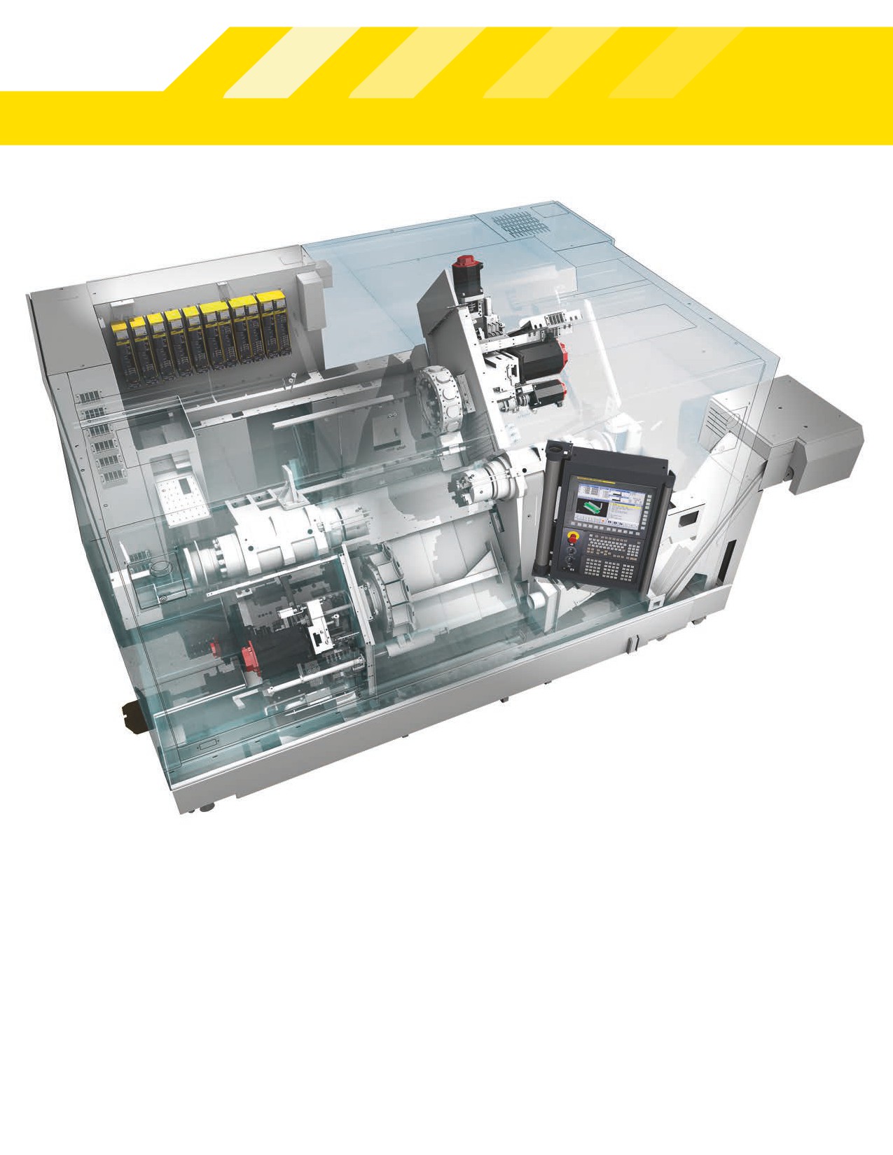
Series 0i MODEL F
FANUC controls have a world-class reputaton for performance, precision, reliability and familiar operaton. This reputaton makes
them popular with the most demanding producton managers, operators and maintenance engineers. FANUC is the world’s leading
CNC manufacturer, with more than 3.7 million controls installed worldwide.
The FANUC Series 0i - MODEL F is the newest generaton in the Series 0i control systems. The Series 0i brings faster, more accurate
performance to a wide range of milling, turning, punching and grinding applicatons with more standard features, more advanced
capabilites and faster communicatons than ever before. The Series 0i control is the industry’s most reliable system with a Mean Time
Between Failure rate of 52 years.
2
888-FANUC-US (888-326-8287)
The first choice for tool room and production turning applications
»»
Support for up to 12 servo axes, 4 simultaneous
interpolated axes, 4 spindles and 3 independent PMC
machine ladders as well as multple part-program paths
and high-speed auxiliary machine functons
»»
Standard features include many advanced features
typically associated with higher-end control systems
»»
Available with 8.4”, 10.4”, or 15” display and QWERTY
or ONG keyboard
»»
The optonal FANUC Data Server offers high-response
Ethernet, up to 16 GB part program storage and large
transfer buffers for Direct Numerical Control (DNC)
»»
Operator-friendly set-up guidance with FANUC’s powerful
and intuitve conversatonal programming or the industry
standard G-Code programming for fast and easy job
changeovers
The Series 0i - MODEL F is the next generaton in the highly
»»
Teach-and-playback mode makes use of electronic hand
popular Series 0i and integrates many features found on
wheels and intuitve conversatonal programming to
the Series 30i-MODEL B. The Series 0i-F offers more axes,
program parts without learning G-Code
ladders and paths, as well as high-speed auxiliary machine
»»
Available web-based sofware applicatons for monitoring
functons and an expanded list of standard features. Addi-
machine and job status with a smartphone or tablet
tonal features available on the Series 0i - MODEL F include
»»
Type 3 and Type 5 versions of the Series 0i - MODEL F are
15” display, QWERTY keyboard, I/O Link i, high-speed rigid
available in milling and turning configuratons. These
tapping, tolerance control, axis name expansion, program
basic versions are a cost-effectve opton for straight-for-
folder management, quick program restart, flexible path
ward, commodity type producton or for machine tool
axis assignment, mult-path PMC functon, ladder dividing
builders who want to add their own functons. See the
table on page 14 for specificatons.
management, EtherNet/IP and PROFINET.
3
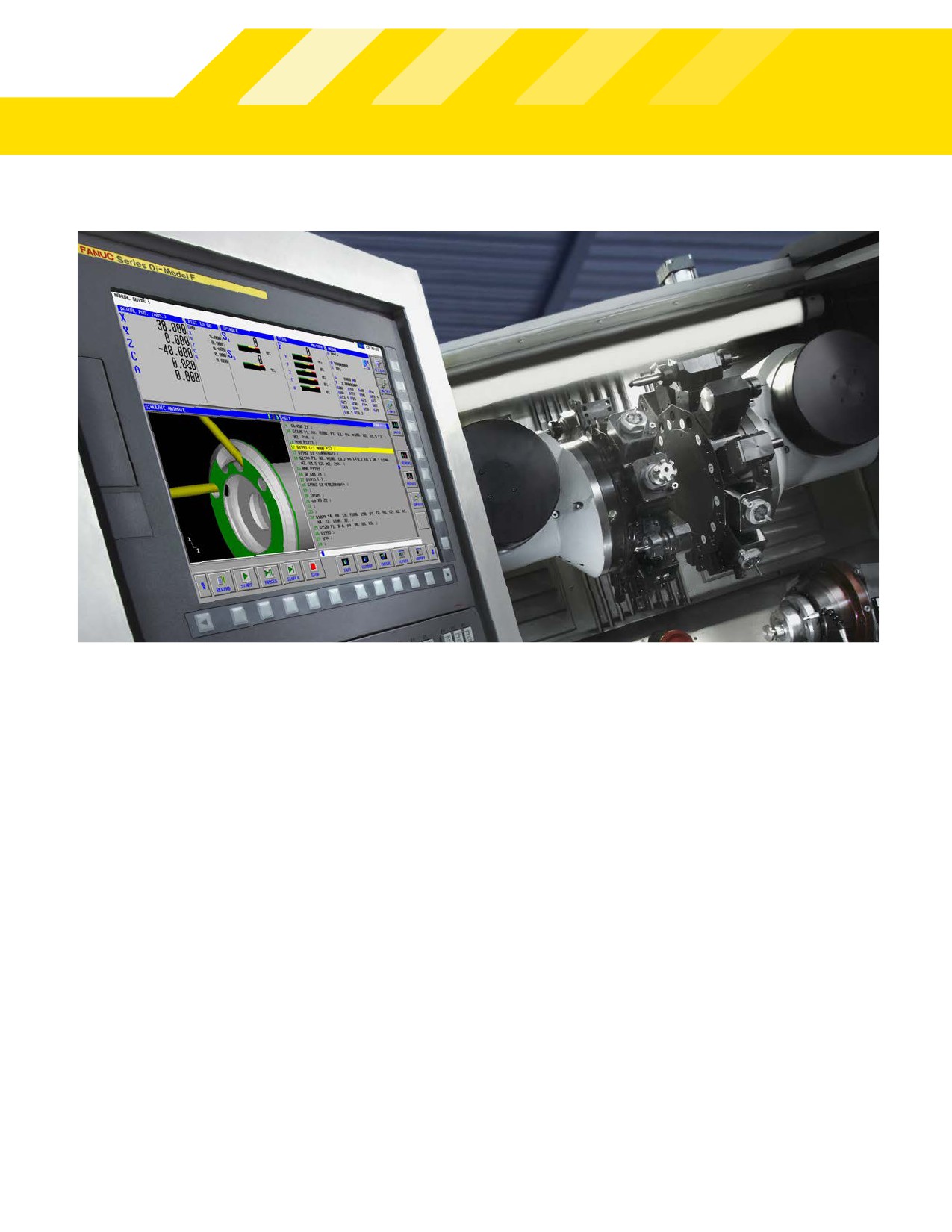
Optimized Speed
Tool Retract & Recover
The Series 0i-F features a suite of advanced moton control
Tool retract and recover simplifies tool inspecton and
sofware functons to reduce cycle tmes while enhancing part
replacement while machining. When actvated, the tool safely
accuracy and extending machine life. Examples include High
retracts from the part and then can be manually moved to an
Response Vector Control (HRV 3), an advanced form of field
inspecton positon. When released, the tool moves back
oriented control that uses high-speed DSPs and nano interpo-
along the path created by the manual moves.
laton to improve surface finish, cycle tmes and accuracy.
Path Synchronization
Bell-Shaped Acc/Dec
M-codes are used to make one path wait for the other path to
Bell-shaped acc/dec minimizes machine shock and while
complete an operaton before proceeding. One path can also
reducing the tme it takes to accelerate and decelerate. This
be commanded to wait untl another path reaches a specified
can be applied to rapid contouring and tapping motons.
absolute coordinate positon before contnuing.
AI Contour Control
High-Speed Ethernet
AI Contour Control (AICC I/AICC II) uses advanced look-ahead
The 100-MBit Ethernet interface allows the CNC to be
algorithms to determine optmal feedrates and acceleraton.
integrated into a network for high-speed part program
This can reduce cycle tmes and improve accuracy, which
transfers and the collecton of process related data. It also
is especially beneficial when machining complex, curved
supports remote troubleshootng from the maintenance
surfaces such as aerospace or automotve parts or metal dies.
department or a machine tool builder anywhere around the
world. Because the Ethernet port does not use a public oper-
4
888-FANUC-US (888-326-8287)
atng system, it is practcally “hacker-free” and virus immune.
operatons can be performed on a program or a complete
folder. Machine tool builder files are separated from user
Part Program Management
programs and macros to avoid accidental modificaton or
The Series 0i - MODEL F provides up to 2MB of nonvolatle
deleton.
internal memory for part program storage. Additonal part
program storage using ATA or CompactFlash memory cards is
Program Restart
available. The optonal FANUC FAST Data provides up to 16GB
Program Restart allows mid-program startup when the pro-
of flash memory. Part programs stored in external memory
gram was interrupted for a tool inspecton or if the machine is
cards or in the FAST Data Server can be edited and executed
stopped for a prolonged break.
just like internal memory.
Multiple Part Program View
32-Alphanumeric Character Program Names
The enhanced part program display provides more insight
The Series 0i-F now allows program names with up to 32
into the part program calling structure and simplifies verifi-
alpha-numeric characters so it is compatble with Series 30i-B.
caton and debugging. It displays the actve part program/
subprogram blocks in detail with interpreted values replacing
Part Program Folders
items such as macro variables statements. If a subprogram is
Organize part programs and macros by categories such as
actve, it also displays the name of the calling parent program.
libraries, customers or jobs. Copy, move and input/output
A second window displays the original part program with the
macro variable statements.
Productivity Advantages
• Nano precision interpolaton for the highest quality
• Compatbility with all previous versions of the Series
surface finish during contouring
0 and 0i-MODELS A, B, C and D, as well as hardware
and programming compatbility with the FANUC
• High-speed machining for faster, beter quality parts
Series 30i/31i/32i-MODEL B.
• Cuter Compensaton for direct input from part
• Consistent operatons minimizes or eliminates the
drawings and increased tooling flexibility
need for additonal training
• Canned cycles and custom macros for simplified part
• Existng part programs run without modificaton
programming
• Simple part programming and operaton
• Skip cycle interface for probe measurements
• Operator-friendly graphic display for visual part
• Tool management for maximum machine utlizaton
program verificaton
• Ethernet connectvity
• Comprehensive help functons
5
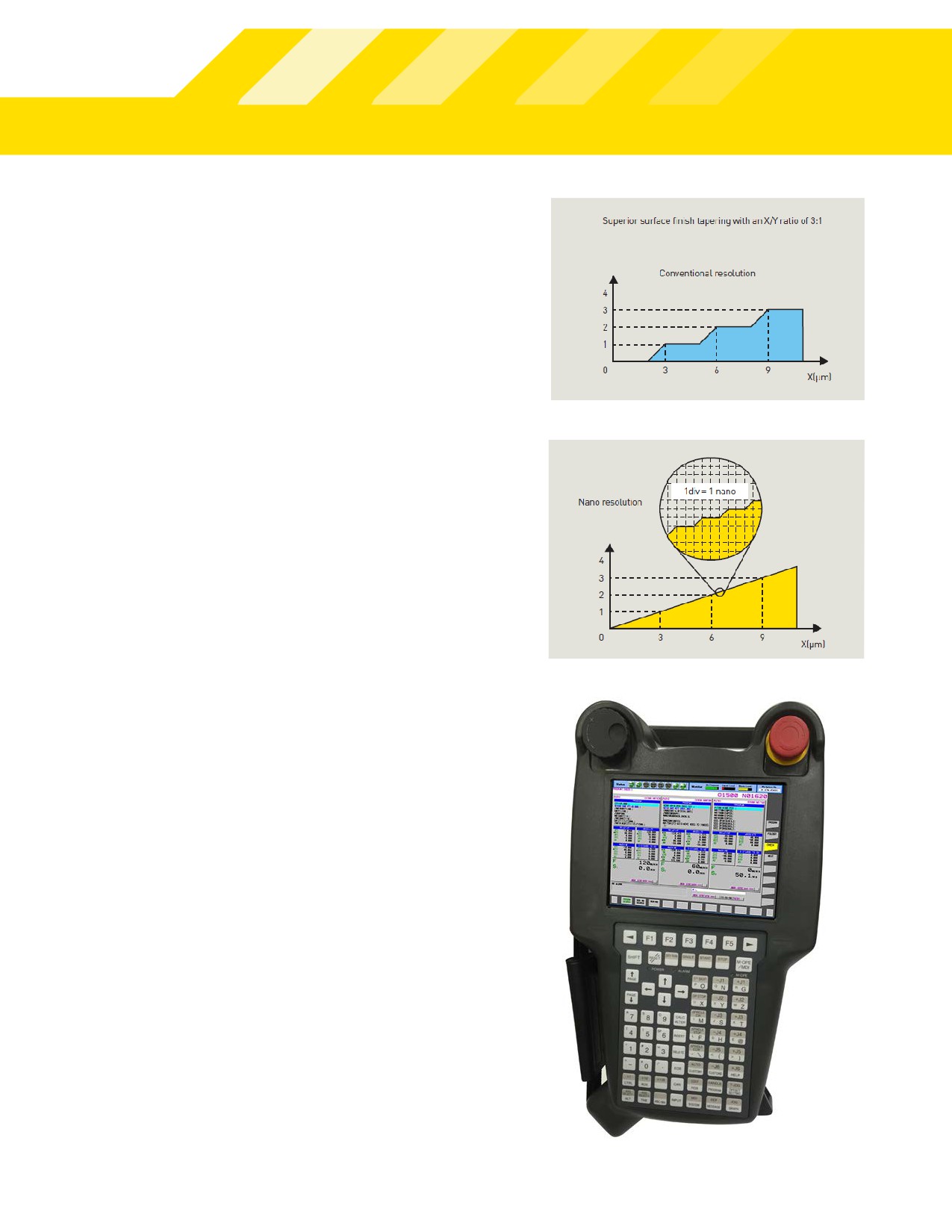
CNC System-Wide Nanometer Precision
The FANUC Nano CNC System achieves high-quality machining
by coordinatng high-precision operaton in nanometers and
state-of-the-art servo technology. With nano interpolaton, po-
siton commands for the digital servo control unit are computed
at the nanometer level, while the SERVO HRV and SPINDLE
HRV controls provide incredibly fast control cycle tmes. The
high-resoluton pulse coders on the FANUC αi-B series AC SERVO
MOTOR supplies highly accurate feedback to ensure the highest
quality machining is achieved.
iPendant
The FANUC iPendant is a factory hardened, portable display
and operaton panel with an available touch-panel interface.
The iPendant can be used as the primary display for simple
applicatons or as an additonal display to allow the operator
to get closer to the workpiece.
The iPendant supports all standard Series 0i-F screens for op-
eraton, programming and maintenance. Customized machine
operaton keys are available with a transparent key sheet.
Keyboard functons can be switched between Manual Data
Input (MDI) mode for data entry/program editng or machine
operaton mode where the keys are used for manual axis
moton, miscellaneous operatonal functons and automatc
machine operaton. iPendant can also be equipped with a small
manual pulse generator device for manual axis operaton and a
USB port for file I/O.
6
888-FANUC-US (888-326-8287)
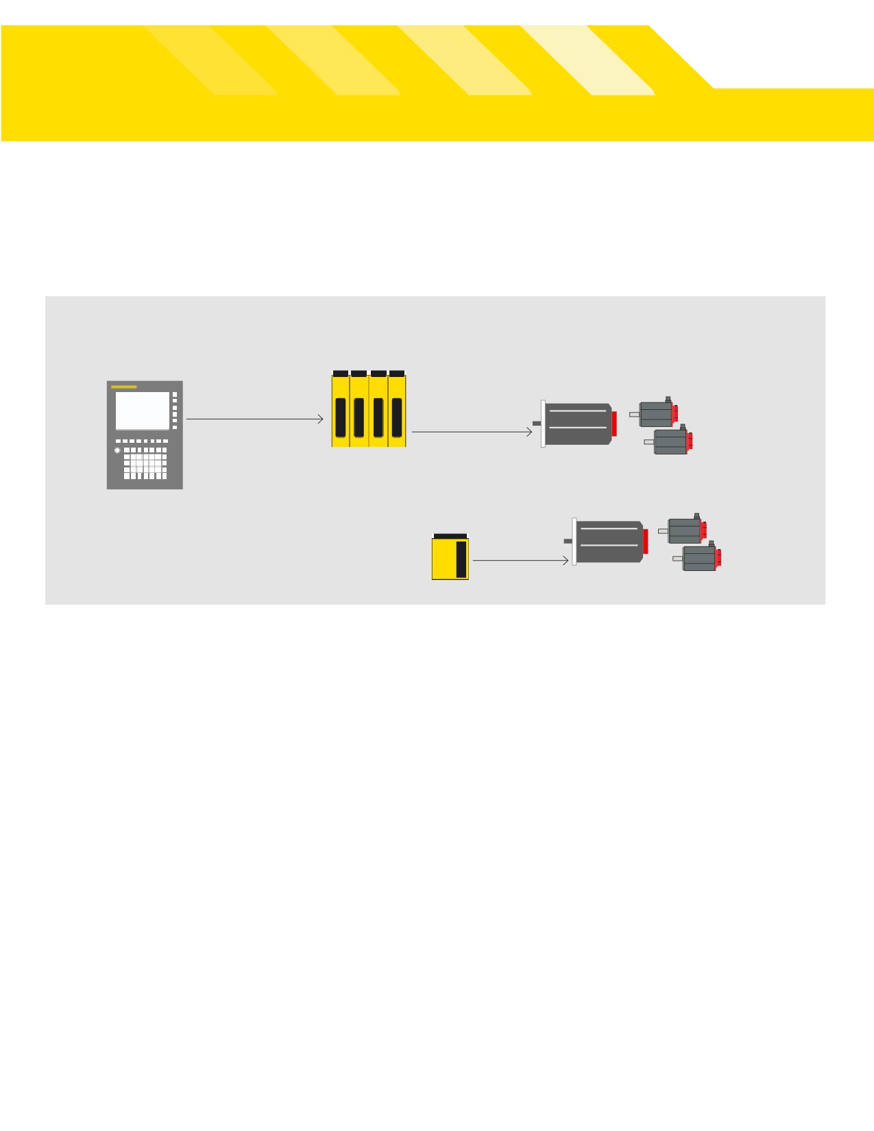
Control, Drives & Sofware -
A Perfect Combinaton
Drive subsystem
βiS/αi βi/αi SERVO motor
FFSB
1st channel
Series βi/αi SERVO
βi/αi spindle motor
Series 0i - MODEL F
2nd channel
βi/αi SVSP
A great CNC system is the perfect combination between
High quality and reliability coupled with simple maintenance
control, drives, I/O and connectivity. That’s what FANUC
are key factors in drive components from FANUC. Modern
gives you for optimum machine tool performance.
bus-systems and connector technology simplifies interconnec-
tons and maximizes operatonal reliability.
The Series 0i-F is compatible with both Alpha i and Beta i
amplifiers and motors to achieve optimal performance.
High-efficiency drive systems pump energy back into the
power line when the machine is deceleratng, and when
Display screens can be customized to suit the requirements
combined with cycle tme reductons, they can significantly
of the operator using C-Executer or FANUC Picture that simpli-
reduce electrical power consumpton. Small motor outlines
fies the construction of custom screens with icon-driven graphic
and minimum footprint amplifier designs reduce the floor
elements.
space required for the machine tool and electrical cabinets.
With Dual Check Safety, the Series 0i - MODEL F has all the
required safety functions integrated into the CNC to comply with
European safety standards.
7
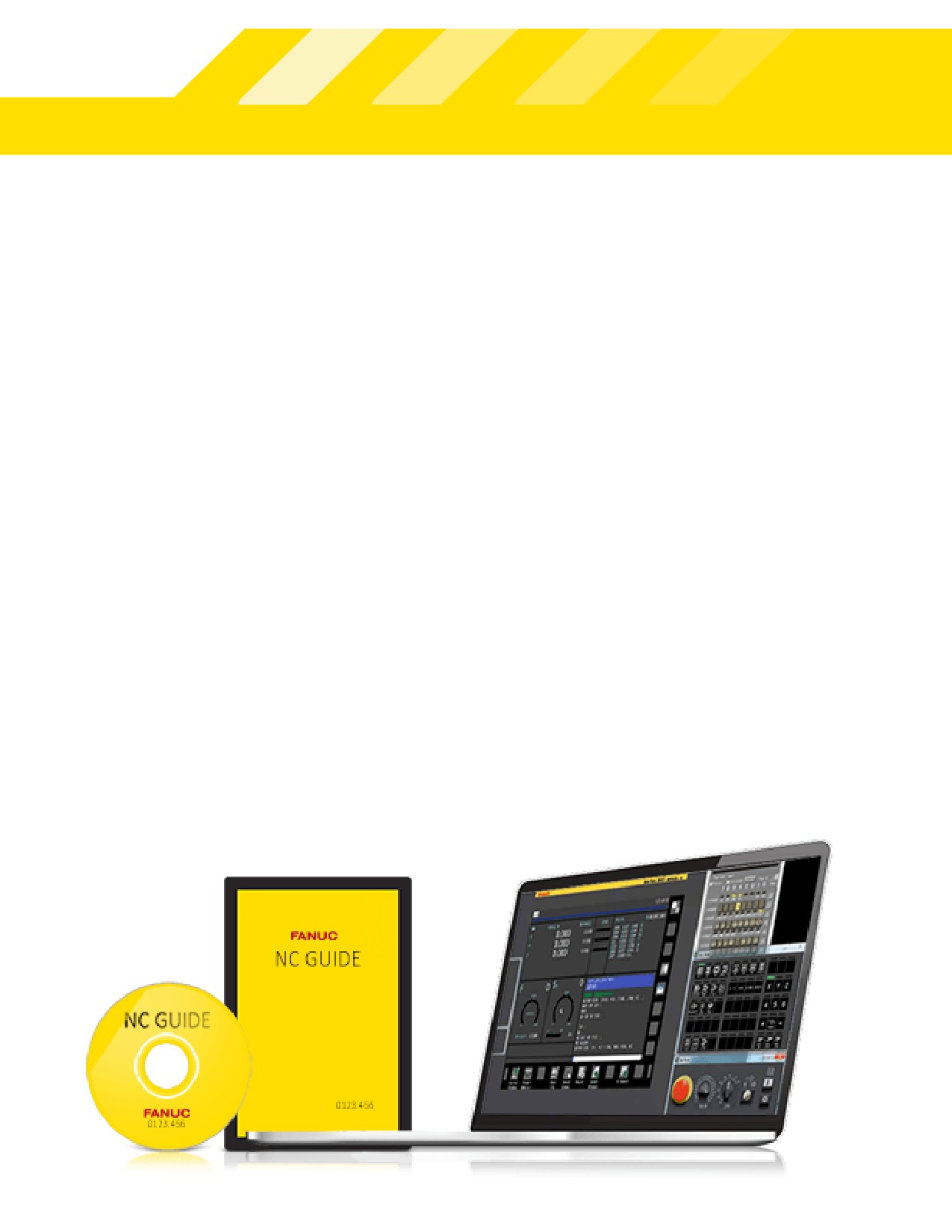
NCGuide - Effectve Training Environment
NCGuide is an authentc simulaton of a FANUC CNC that
expand their knowledge by learning the features available
runs on a PC, providing a realistc operaton and part pro-
with newer controls - even before they are installed.
gramming environment at a fracton of the cost of using
For the most realistc and effectve learning environment,
a producton machine tool. This translates into lower train-
each user can quickly setup a configuraton to emulate a
ing costs, as comprehension and retenton is enhanced.
partcular machine’s CNC.
Students can perform hands-on exercises in an ergonom-
ically friendly environment - away from the noise of the
Part Programming Training
factory floor. Operators, programmers and maintenance
NCGuide supports both conventonal G-Code part program-
engineers can all practce common procedures or develop
ming with tool path simulaton, and the powerful, easy-to-
optmized processes without risks to people, tooling or
use, MANUAL GUIDE i conversatonal part programming
machines.
with 3D tool path and part geometry visualizaton.
Users can create and edit machining center, lathe and
Operational Training
compound machining part programs, generate cycle tme
NCGuide is ideal for operatonal training. All standard CNC
estmates and create and test Custom Macro subroutnes.
operatonal screens can be selected and all standard pro-
The tool path simulaton lets users visually verify a part
cedures can be practced. NCGuide also supports custom
program, to see the effect of workpiece and tool offsets
screens developed by the machine tool builder. Users can
and to observe the effects of canned cycles and advanced
create and edit part programs, search for words and safe
interpolaton modes. MANUAL GUIDE i conversatonal part
start blocks, upload and download part programs and test
programs can be developed on the simulator and then con-
for syntax and tool path geometry errors. Workpiece, tool
verted to conventonal G-Code to run on any FANUC CNC.
geometry and tool wear offsets can all be edited and their
effects visualized to enhance understanding. Users can
8
888-FANUC-US (888-326-8287)
MANUAL GUIDE i
MANUAL GUIDE i conversatonal programming is available
for the Series 0i controls with 10.4’’ or 15’’ LCD displays. It
provides fast and efficient programming for milling, turning
and mill-turn centers. The screens and menus are intui-
tve and the 3D verificaton graphics are clear, providing
a comfortable part programming environment - even for
complex parts.
A part program can be generated in a few simple steps.
Graphical, user-friendly symbols and pop-up menus over-
lay a single main screen, which includes all the machine
informaton needed to create and execute a part program.
This ensures that the operator is always in control. MAN-
UAL GUIDE i can also be used off the shop floor with the
NCGuide simulaton package. Part programs can be moved
freely between the PC and a wide range of machines.
Powerful G-Code Editor
The Series 0i - MODEL F supports both traditonal CNC
word editor mode and flexible character editng. Charac-
ter editng mode provides a quick and easy way to modify
complex word structures such as custom macros, mathe-
matcal statements and part program comments. The back-
ground editor can display multple programs side-by-side
on the screen so that one part program can be download-
ed and modified while another part program is executng in
the foreground.
9

Integrated safety
Chuck and Tailstock Barriers
The Series 0i-F is available with Dual Check Safety. This integrat-
The Chuck and Tailstock Barrier functon prevents damage to
ed Category 3 safety system offers a high level of safety through
the machine by checking whether the tool tp interferes
redundant monitoring and duplicate paths of breaking power
with either the chuck or tail stock. Setng screens define the
to the servo/spindle amplifier using a single cable. Using built-in
no-entry zones which the tool may not enter. Setngs may
redundancy, a special processor for monitoring safety-related
be entered quickly by jogging the tool to the barrier limit and
parameters, Dual Check Safety guarantees the safety of the
using sof keys to record the positons. If the tool nose enters
system by following the actual position and speed of the servo
the barrier during machining, the axes are stopped and an
motors, spindle motors and the I/O interfaces.
error message displayed.
Basic Functons of Dual Check Safety:
Interference Check
• Brake Monitoring
When tools from two independent paths machine the same
• Safe Spindle Speed (4 ranges)
workpiece simultaneously they can machine in close proxim-
• Safe Servo Axis Speed (4 Ranges, Velocity & Positoning)
ity to each other. If the tools make contact with each other
• Safe Machine Axis Positon (4 ranges)
due to a programming error or a setup error, serious dam-
• Safe Stop
age to the tool and machine can result. Interference Check
• Safe I/O’s
detects any potental collision before it occurs and stops the
• Safety I/O Signal History Functon
machine.
• Safety Spindle Speed Limit Override Functon
• Test Mode Functon for Acceptance Test
Crash Protecton
Unexpected torque disturbance control allows torque limits
Safety I/O Unit
to be set so that the axis will stop or retract when a collision
The safety I/O unit is a single module interface that provides
is detected, reducing damage to the machine.
redundant input and output safety signals when Dual Check
Safety is used, requiring only a single I/O Link i channel.
DUAL
CHECK
SAFETY
10
888-FANUC-US (888-326-8287)
shootng. FANUC experts provide fast local onsite service and free
over-the-phone technical support.
Preventon of Operatonal Errors
Unintentonal mistakes can be reduced by requiring opera-
tors to confirm actons like deletng part programs or startng
programs in the middle. Limits can be placed on the tool and
workpiece offset values entered to prevent machine crashes
due to simple data entry errors.
Unmatched Reliability
Built-In Backup
Downtme on your CNC machine is very expensive, especially
The Built-In Backup feature regularly backs up important data
when you add up the cost of repairs, the lost producton capacity,
to flash memory to minimize downtme from lost machine
and the potental revenue and goodwill lost if you miss customers’
tool builder or user files. This saves tme when experimentng
deliveries. FANUC’s contnuous improvement culture ensures that
or troubleshootng by saving a snapshot of all the existng
our CNC systems are the most reliable available. Statstcally, a
user files and setngs before making any modificatons.
hardware fault occurs only once for every 52 years of productve
service.
Simplified Servo & Spindle Tuning
Quickly and easily determine the recommended servo and
Through our commitment to our Service First philosophy, we offer
spindle servo tuning parameters by simply pressing a sofkey
lifetme parts and maintenance support for all of our products as
on a built-in screen. This eliminates the need for costly special-
long they are in use. We provide convenient local parts inven-
ized resources. If higher precision is required, optmum velocity
tories and economical repair and return services to help ensure
gain for each servo axis can be adjusted automatcally using the
our customers’ machines are available for producton when they
more advanced Parameter Tuning of Velocity Gain tool.
need them.
Maintenance Friendly
The modular design of the bateries and fans means they can be
Extreme Reliability -
replaces quickly and easily without tools. A comprehensive pack-
age of maintenance tools is integrated into the CNC to help keep
Maintenance Friendly
your machine running and making parts. A snapshot of any CNC
screen can be captured to a memory card to be used in trouble-
11
drive is limited during acceleraton to reduce energy usage.
The CNC’s PMC interface can also be used to turn off pow-
er-hungry peripherals when the machine is not in cycle. The
energy usage of peripheral devices can be monitored by
entering their average power consumpton and controlling
PMC addresses.
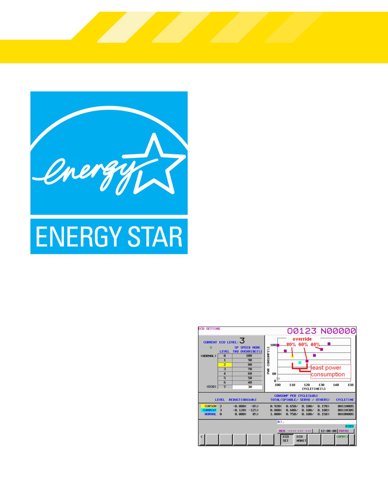
Energy Monitoring & Optmizaton
The CNC monitors and displays the real-tme energy
usage and savings allowing part programs to be
optmized for maximum efficiency. The data can also
be collected via Ethernet and saved for analysis.
The ECO monitoring screen displays a comprehensive
analysis of power consumpton and the benefi ts achieved
with eco machining.
Energy Saving
Studies have shown that approximately 20% of a machine’s
running costs can be atributed to electrical energy consump-
ton, primarily for hydraulic and pneumatc pumps, and the
servo and spindle drive systems.
The servo motors in a moton system are contnuously accel-
eratng and deceleratng as they change speed and directon.
The state-of-the-art FANUC AC drive systems use high-speed,
high-efficiency switching circuits to direct the energy back
into the main electrical supply when an axis is deceleratng,
reducing the net energy used.
The FANUC energy saving level selectng functon allows the
user to optmize the balance between the fastest (normal)
machining speed and the lowest energy consumpton. When
The ECO setng screen provides visualizaton of energy consumpton to
the ECO level is set above level 0, the torque of the spindle
enable the selecton of the best eco-machining setng.
12
888-FANUC-US (888-326-8287)
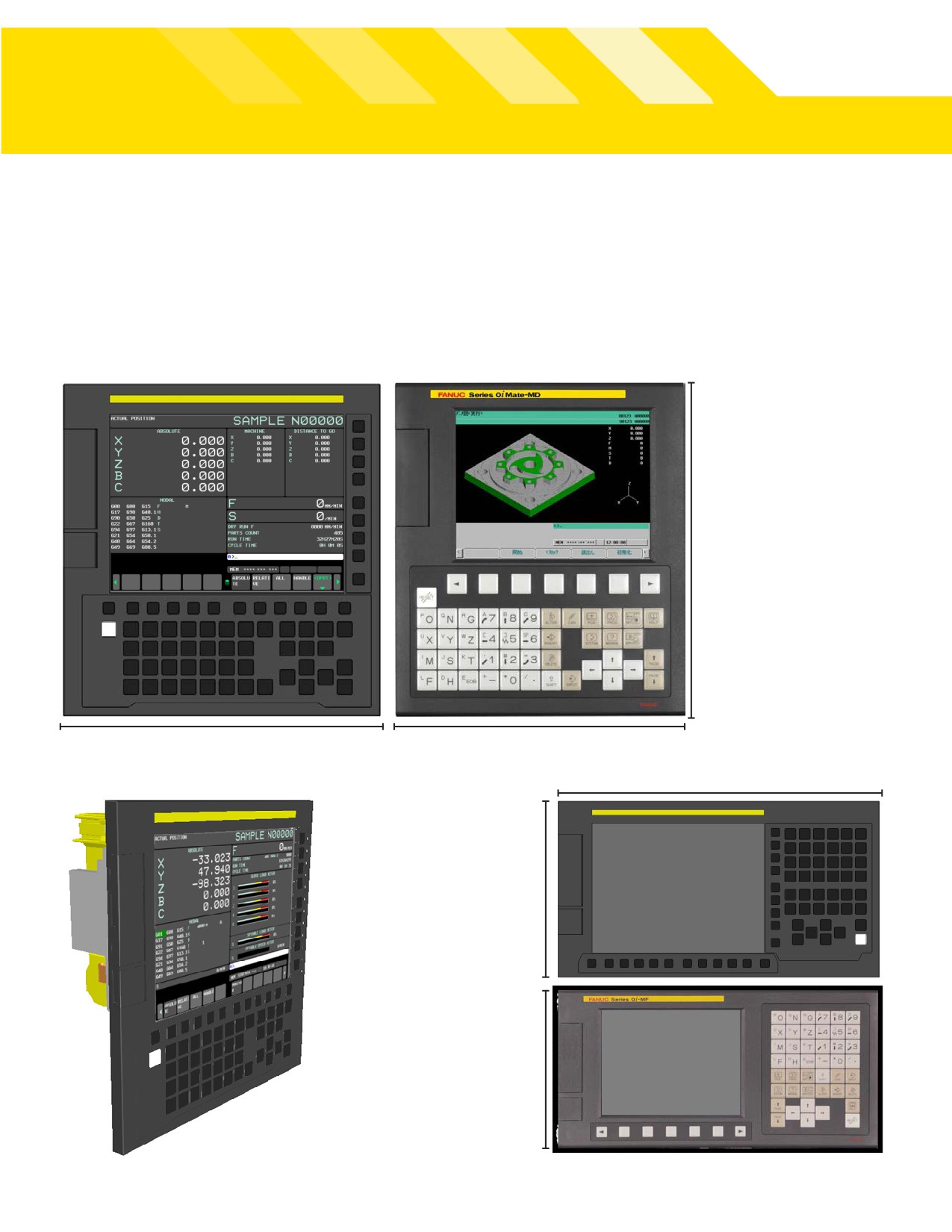
Modernized FANUC Series 0i-F Design
Conventonal operatng system can easily transiton from the standard 8.4”LCD/MDI unit to
the new 10.4 inch screen display unit with flat and sophistcated design.
10.4”LCD/MDI Unit (Vertcal)
8.4”LCD/MDI Unit (Vertcal)
300mm tall (same as 8.4”)
290mm wide
260mm wide
400 mm wide
10.4”LCD/MDI Unit (Horizontal
220mm tall
8.4”LCD/MDI Unit (Horizontal)
200mm tall
13
Series 0i Technical Guide
Series 0i-F Type 1
Series 0i-F Type 3
Series 0i-F Type 5
ITEM
Milling (M)
Turning (T)
Punching (P)
M
T
M
T
Control Axis
Controlled paths
2
2
1
1
1
1
1
Max. total number of control axes per path
11 / 9
12 / 9
7
6
6
6
6
Max. simultaneously controlled axes per path
4
4
4
4
4
4
4
Loader control paths
2
2
0
1
1
1
1
LCD
8.4”/10.4”/15”
8.4”/10.4”/15”
8.4”/10.4”/15”
8.4”/10.4”
8.4”/10.4”
8.4”/10.4”
8.4”/10.4”
Touch Screen
PANEL i
-
-
-
-
Nano interpolaton
Part program storage
512K-2MB
512K-2MB
512K-2MB
512K-2MB
512K-2MB
512K-2MB
512K-2MB
-
-
-
5K-24K
5K-24K
5K-24K
5K-24K
PMC/L functon
PMC
24K-100K
24K-100K
24K
-
-
-
-
system
I/O Link i DI/DO points
2048/2048
2048/2048
2048/2048
1024/1024
1024/1024
1024/1024
1024/1024
Embedded Ethernet
Fast Ethernet
-
-
-
-
Memory card program edit & operaton
Data server editng/ operaton
-
-
-
-
MANUAL GUIDE i
TURN MATE i
-
-
-
-
AI contour control I & II
(I/II)
*(I/II)
*(I)
*(I/II)
*(I/II)
*(I)
*(I)
Nano smoothing
-
-
-
-
-
Jerk control
-
-
-
-
-
Spindle control with servo motor
-
Protecton of data at eight levels
Dynamic display language switching
Macro executor + C Language executor
FANUC PICTURE exectutor
NCGuide
-
-
-
-
-
Program transfer tool
CNC setng tool
Tool management functon: 1000 pairs
*
*
-
-
-
-
-
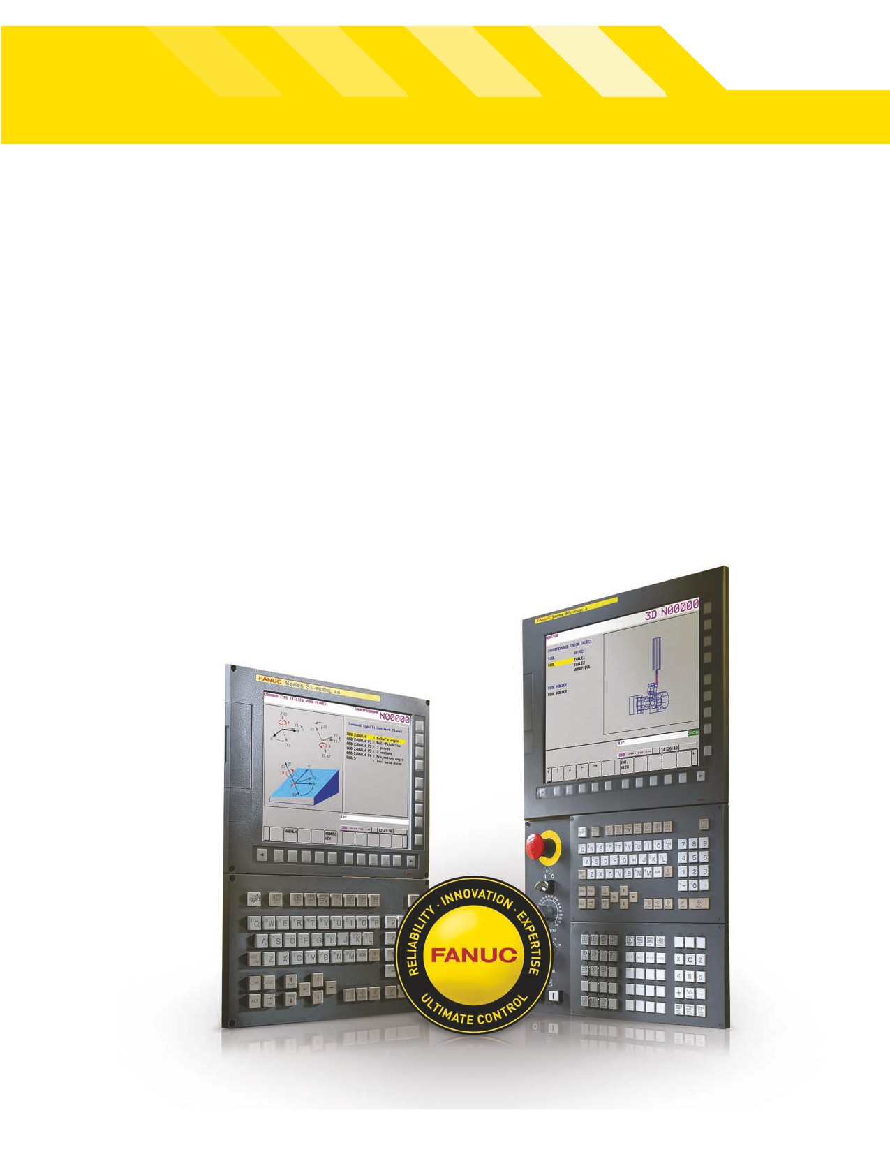
Top 10 Reasons To Choose FANUC
1. FANUC’s world class reliability and 52-year
6. CNC Systems are ready to go in less than 30
MTBF rates maximize machine uptime and
seconds for increased daily production time.
minimize TCO.
7. Boost efficiency with Ethernet-enabled data
2. Lifetime support of FANUC products and parts.
and remote diagnostics.
3. Increase your competitive edge with state-
8. Minimize downtime by separating CNC control
of-the-art technologies that increase quality,
and PC technologies.
efficiency, reliability and reduction of cycle
9. Rely on a world-class partner.
times.
10. The standard interface of FANUC simplifies
4. Minimize training and support costs with con-
integration with robots.
tinuity of operation and upward compatibility
of existing programs on new CNC controls.
5. At-the-machine programming with MANUAL
GUIDE i conversational programming.
15