Lockheed Martin C-130J Super Hercules

C-130J Super Hercules
Whatever the Situation, We’ll Be
There
Table of Contents
Introduction
Note: In general this document and its contents refer
INTRODUCTION
1
to the C-130J-30, the stretched/advanced version of
RECENT CAPABILITY/PERFORMANCE UPGRADES 4
the Hercules.
SURVIVABILITY OPTIONS
5
GENERAL ARRANGEMENT
6
GENERAL CHARACTERISTICS
7
TECHNOLOGY IMPROVEMENTS
8
COMPETITIVE COMPARISON
9
CARGO COMPARTMENT
10
CROSS SECTIONS
11
CARGO ARRANGEMENT
12
CAPACITY AND LOADS
13
ENHANCED CARGO HANDLING SYSTEM
15
COMBAT TROOP SEATING
17
Paratroop Seating
18
Litters
19
GROUND SERVICING POINTS
20
GROUND OPERATIONS
21
The C-130 Hercules is the standard against which
FLIGHT STATION LAYOUTS
22
military transport aircraft are measured. Versatility,
Instrument Panel
22
reliability, and ruggedness make it the military
Overhead Panel
23
transport of choice for more than 60 nations on six
Center Console
24
continents. More than 2,300 of these aircraft have
USAF AVIONICS CONFIGURATION
25
been delivered by Lockheed Martin Aeronautics
Company since it entered production in 1956.
MAJOR SYSTEMS
26
During the past five decades, Lockheed Martin and
Electrical
26
its subcontractors have upgraded virtually every
Environmental Control System
27
system, component, and structural part of the
Fuel System
27
aircraft to make it more durable, easier to maintain,
Hydraulic Systems
28
and less expensive to operate. In addition to the
Enhanced Cargo Handling System
29
tactical airlift mission, versions of the C-130 serve
Defensive Systems
29
as aerial tanker and ground refuelers, weather
PERFORMANCE
30
reconnaissance, command and control, gunships,
firefighters, electronic recon, search and rescue,
Maximum Effort Takeoff Roll
30
and flying hospitals.
Normal Takeoff Distance (Over 50 Feet)
30
The newest Hercules, the C-130J, has the same
Maximum Effort Landing Roll
31
rugged good looks of its predecessors, but in fact is
Normal Landing Distance (Over 50 Feet)
31
a greatly improved airplane with the performance
Payload Range
32
and capability to prove it. Compared to the earlier
WORLD RECORDS
33
C-130E, the maximum speed is 21 percent higher,
1
Introduction
Introduction
climb time is reduced by up to 50 percent, cruising
The C-130J-30, the stretched/advanced version
altitude is up to 40 percent higher, and range is up to
of the Hercules, offers operators 55 feet of cargo
40 percent longer. With new engines and props, the
compartment length - an additional 15 feet over the
J has set 54 world records for rate of climb, cruise
original “short” aircraft. The additional 15 feet is
speed, and both distance and altitude with payload.
provided by inserting a 100-inch forward and an
80-inch aft plug to the fuselage. This translates into
30 percent more usable volume for increased seating,
litters, pallets, or airdrop platforms. This additional
capability provides significant advantages when
transporting personnel or delivering priority cargo by
reducing the number of sorties needed to complete
the mission.
In addition to the significant increases in
operational capability and performance, the C-130J
offers a greater value when compared to any other
tactical airlifter: System reliability and maintainability
are improved by up to 50 percent; maintenance
man-hours per flight hour are decreased by up to
68 percent; and flight and maintenance manpower
The C-130J incorporates these major improvements:
are reduced by up to 50 percent, resulting in a
47 percent lower squadron operating and support cost.
• A new propulsion system featuring four
4,591 pshp Rolls-Royce AE2100D3 engines
and composite, six-bladed Dowty Aerospace
R391 propellers with significantly improved
fuel economy and high-hot performance.
• Two-person flight station including four
multifunctional LCD displays; two holographic
head-up displays (HUD); and electronic, digital
readouts for aircraft operating, communicating,
and navigating systems. The displays and aircraft
general lighting are compatible with the USAF’s
night-vision imaging system.
• A 1553 data bus, two mission computers,
and two backup bus interface units provide dual
redundancy for the Hercules’ systems. In addition,
the computers provide for an integrated diagnostics
system that monitors and records the status of the
aircraft’s structure and systems.
2
3

Recent Capability/Performance Upgrades
Recent Capability/Performance Upgrades
Subsequent to the USAF Operational Test
• Center Wing Box improvement to provide
and Evaluation Acceptance of the C-130J combat
Enhanced Service Life (ESL) by strengthening
delivery aircraft in 2006, several performance
structural components such as Hat Sections
enhancements by Lockheed Martin Aeronautics
(stringers), Beam Caps and Webs, Wing Attach
were developed, tested, verified, qualified,
Fittings, and Engine Truss Mounts. The ESL wing
accepted, and incorporated into the basic aircraft
was originally developed for the USAF Special
configuration. These include:
Operations C-130s in support of Severe
Mission Operations.
• Terrain Awareness and Warning System (TAWS),
a forward -looking awareness and warning system,
• Reduced Vertical Separation Minima (RVSM) for
for improved in-flight situational awareness.The
worldwide operations in CNS/ATM controlled
TAWS operates in conjunction with the existing
airspace. Access to RVSM airspace increases
Ground Collision Avoidance System (GCAS) as
true air speed and range while reducing fuel
independent complementary systems providing
consumption, e.g., enhances long-range
visual and obstacle Voice Warning Alerts (VWA)
cruise performance.
to the crew.
• Data Transfer and Diagnostic System (DTADS)
• Identification Friend or Foe (IFF) Transponder Mode S
Interface Unit for maintenance management
with Enhanced Surveillance for use in civil
of critical aircraft systems using a Windows
Communications, Navigation, and Surveillance/Air
Operating System. DTADS encompasses in-flight
Traffic Management (CNS/ATM) airspace. The IFF
and post-flight analysis, ground maintenance
has growth capability to Mode 5.
processing, structural health monitoring, and
engine life management. DTADS is scheduled
• Communications, Navigation, and Identification
to become available in 2010.
(CNI) common software upgrade developed for
all customers including updated chute ballistic
tables, new track offset, additional drift down
performance pages, and re-host of the Takeoff
Survivability Options
and Landing Data (TOLD) from the CNI to the
Mission Computer (MC).
• Small Arms Armor Kit, available as Customer-
• TOLD re-hosted in MC Operational Flight
Furnished Equipment (CFE), provides protection
for the pilot and co-pilot, crew station and
Program (OFP), enabling additional and enhanced
bunk, forward and aft loadmaster stations,
capabilities pertaining to charts and calculations
for hot/high takeoffs, assault landing weight,
paratroop doors, nose wheel well, and liquid
oxygen converter.
modified minimum field length maximum effort
takeoff, climb gradients, wind corrections, and
temperature deviation expansion to ISA +/-45°C.
• Explosive Suppressant Tank Foam is available as
CFE for the main and auxiliary fuel tanks, which
aids in protecting against ballistic penetration
and lightning strikes.
4
5
General Arrangement
General Characteristics
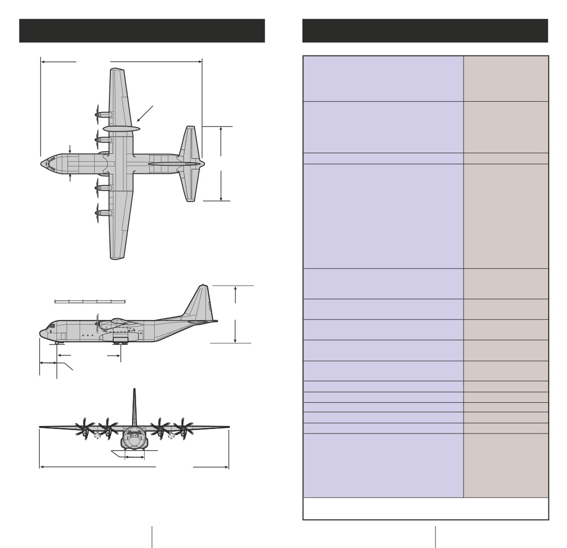
112 ft 9 in.
Dimensions
(34.37 m)
Wingspan
132 ft 7 in.
Length
112 ft 9 in.
Height
38 ft 10 in.
External Fuel Tanks
(Optional)
Cargo Floor
Length (Floor + Ramp)
55 ft + 10 ft 8 in.
Width (Minimum)
10 ft
Height (Minimum)
9 ft
Area (Floor + Ramp)
550 + 107 sq ft
52 ft 8 in.
Cargo Volume
6,022 cu ft
(16.05 m)
Weights
Max Takeoff Weight (2.5g)
164,000 lb
14 ft 2 in.
(4.32 m)
Max Takeoff Weight (2.25g)
175,000 lb
Max Landing Weight, 9 fps
162,000 lb
Max Landing Weight
164,000 lb
Operating Weight Empty
87,667 lb
Max Payload (2.5g) (Note 2)
47,333 lb
Max Fuel (JP-8)
43,562 lb
Max Zero Fuel Weight (Note 1)
129,000 lb
Max Zero Fuel Weight (Note 2)
135,000 lb
Performance
Max Cruise Speed
355 kts
0
10
20
30
40
50
Airdrop Speed
Up to 250 KIAS
FEET
38 ft 10 in.
Takeoff Dist Over 50 ft (S/L, ISA, 164,000 lb)
(11.84 m)
Normal
5,850 ft
Takeoff Roll (S/L, ISA, 164,000 lb)
Max Effort
3,100 ft
Landing Dist Over 50 ft (S/L, ISA, 135,000 lb)
40 ft 4 in.
Normal
3,000 ft
(12.30 m)
Ground Roll (S/L, ISA, 135,000 lb)
11 ft 6 in.
Max Effort
1,630 ft
(3.50 m)
Max Range (Without Tanks)
3,510 n.mi
Range (40,000-lb Payload - 2.5-g Mission)
2,200 n.mi
Cruising Altitude (T/O at MTOW)
27,000 ft
Service Ceiling (T/O at MTOW)
29,000 ft
Crew
2 Pilots + Loadmaster
Power Plant
4 Rolls-Royce
14 ft 3 in.
(4.34 m)
AE2100D3, 4,591
132 ft 7 in.
pshp Turboprop
(40.38 m)
Engines (4 Dowty R391,
6-Blade Propellers,
All Composite)
Note 1: Structural Reserve Fuel
Note 2: With Wing Bending Relief Fuel
6
7
Technology Improvements
Competitive Comparison
Cargo
#463L
CDS
Combat
Para-
Model
Litters
Floor
Pallets
Bundles
Troops
troops
C-130J-30
55 ft
8
97
24
128
92
A400M
58 ft
9
66
24
120
120
(Proposed)
C-17
65 ft
18
36
40
102
102
C-130E/H
40 ft
6
74
16
92
64
C-130J
(Short)
AIRCRAFT
• Two-Person Flight Deck Crew
• Provisions for Auxiliary Crew Member Station
• Ergonomically Designed Cockpit
• Interchangeable Panel Layout
• Soft Panels
• Advanced Communications and Navigation Systems
• New Electrical System
• 1553B Data Bus Architecture
• Integrated Diagnostic System
• Head-Up Display (Dual) - Certified Primary
Flight Instrument
• 250 KIAS Airdrop Speed Ramp and Door
• Single Cross-Ship Fuel Manifold
• Defensive Systems
• Air Traffic and Ground Collision Avoidance Systems
• Enhanced Cargo Handling System
(USAF Configuration)
• Color Digital Map Display
• Color Weather Radar/Ground Mapping Radar
• Night-Vision Imaging System (NVIS) Compatible
(Flight Deck and Cargo Compartment)
PROPULSION
• Rolls-Royce AE2100D3, Flat Rated at 4,591 pshp
• Full-Authority Digital Electronic Control (FADEC)
• Dowty R391 Six-Bladed Composite Propeller
8
9
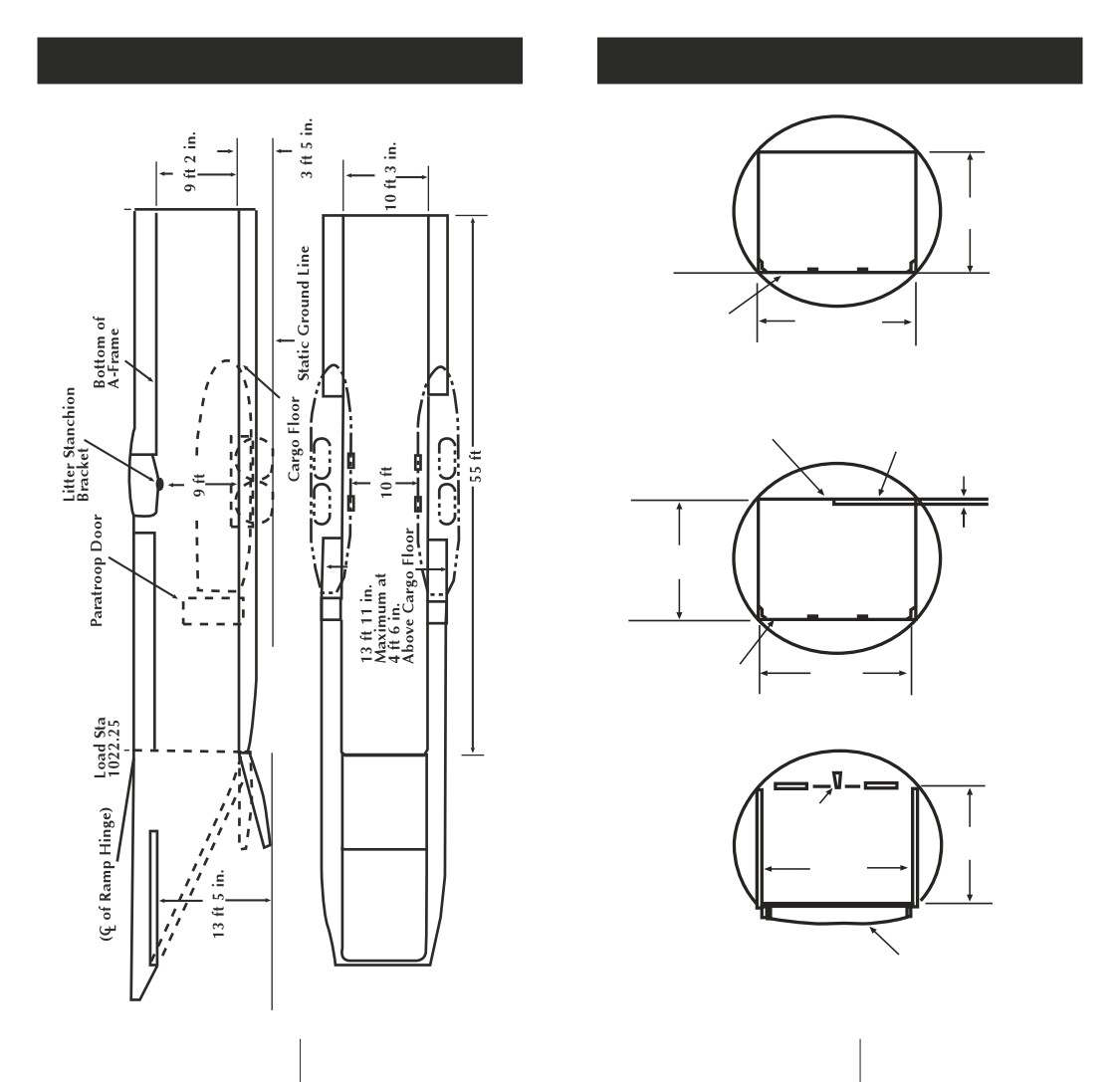
Cargo Compartment
Cross Sections
9 ft 2 in.
Cargo Floor
10 ft 5 in.
Forward
Litter
Stanchion
Wing Center Section
Bracket
Lower Surface
1 in.
9 ft
Cargo Floor
10 ft
Center
Pendulum
Arm
9 ft
10 ft
Aft
Cargo
Ramp
10
11
80 in.
100 in.
8
7
6
5
4
3
2
1
Cargo
#463L
CDS
Combat
Para-
Model
Litters
Floor
Pallets
Bundles
Troops
troops
C-130J-30
55 ft
8
97
24
128
92
The C-130J-30 Can Carry 90 Percent of the U.S. Army and USAF Combat Equipment
SUMMARY OF CARGO COMPARTMENT CAPACITY AND MAXIMUM ALLOWABLE FLIGHT LOADS
Load Station Centroid
Inch
365
428
517
607
697
787
877
967
1027
1083
1133
Compartment
C
D
E
F
G
H
I
J
K
L
M
2
Ramp
Area
sq ft
32
76
77
77
75
75
77
76
27
71
15
(sq m)
(2.98)
(7.06)
(7.16)
(7.16)
(6.97)
(6.97)
(7.16)
(7.06)
(2.51)
(6.60)
(1.39)
Volume
cu ft
292
684
692
692
678
676
692
684
219
454
73
(cu m)
(8.17)
(19.15)
(19.37)
(19.37)
(18.98)
(18.92)
(19.37)
(19.15)
(6.13)
(12.71)
(2.04)
MAXIMUM LOAD RATE
Maximum Individual
lb
5,700
11,500
21,000
38,000
45,000
45,000
34,000
19,500
3,500
4,500
500
Compartment Capacity
(kg)
(2,585)
(5,216)
(9,525)
(17,236)(20,412)(20,412)(15,422)
(8,845)
(1,588)
(2,041)
(744)
Concentrated Loads -
psi
50
50
50
50
50
50
50
50
50
50
50
All Areas
(kg sq cm)
(3.52)
(3.52)
(3.52)
(3.52)
(3.52)
(3.52)
(3.52)
(3.52)
(3.52)
(3.52)
(3.52)
1,400
1,400
Running Loads
lb/ft
1,400
1,400
3,000
3,000
3,000
1,400
500
500
500
(2,083)
(2,083)
per Treadway
(kg/m)
(2,083)
(2,083)
(4,464)
(4,464)
(4,464)
(2,083)
(744)
(744)
(744)
11
12
12
Running Loads
lb/ft
1,600
1,600
1,600
1,600
1,600
1,600
1,600
1,600
500
500
500
(744)
Between Treadways
(kg/m)
(2,381)
(2,381)
(2,381)
(2,381)
(2,381)
(2,381)
(2,381)
(2,381)
(744)
(744)
11
13
Tongue Load
lb
2,000
2,000
2,000
2,000
2,000
2,000
2,000
2,000
450
450
450
Between Treadways
(kg)
(907)
(907)
(907)
(907)
(907)
(907)
(907)
(907)
(204)
(204)
(204)
11
2,800
2,800
2,800
Palletized and
lb/ft
2,800
3,200
3,200
3,200
1,000
5
(4,167)
(4,167)
(4,167)
5
5
Containerized Cargo
(kg/m)
(4,167)
(4,762)
(4,762)
(4,762)
(1,488)
14
14
6
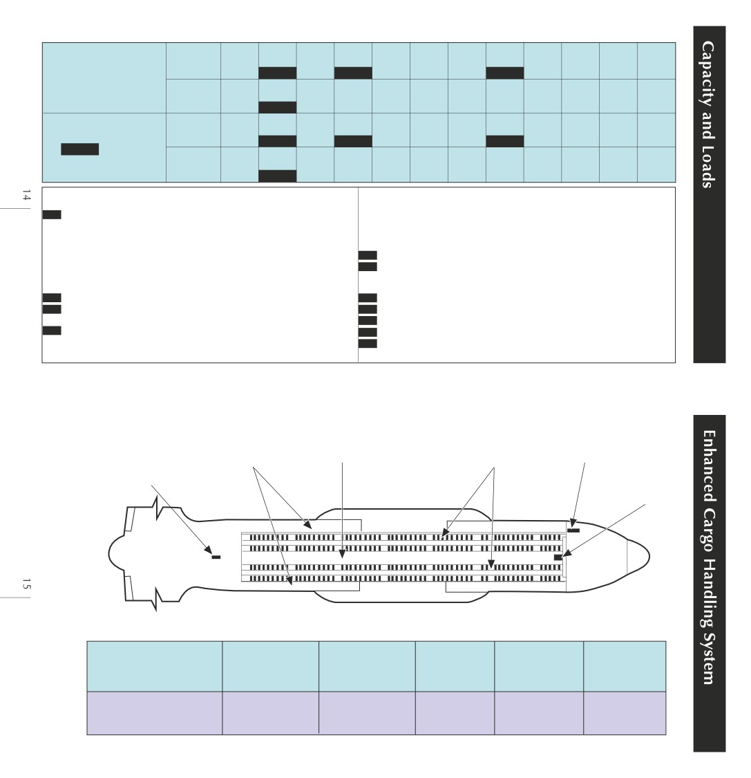
MAXIMUM AXLE LOAD
Pneumatic Tires,
6,000
6,000
6,000
lb
6,000
13,000
13,000
13,000
6,000
2,500
2,500
2,500
Treadways
(2,722)
(2,722)
(2,722)
100 psi (689.5 KPA)
(kg)
(2,722)
(5,897)
(5,897)
(5,897)
(2,722)
(1,134)
(1,134)
(1,134)
7
16
15
Maximum Pressure
5,000
Between
lb
5,000
5,000
5,000
5,000
5,000
5,000
5,000
1,200
1,200
1,200
(2,268)
Treadways
(kg)
(2,268)
(2,268)
(2,268)
(2,268)
(2,268)
(2,268)
(2,268)
(544)
(544)
(544)
7
2,300
2,300
2,300
Hard Rubber Tires
lb
2,300
5,000
5,000
5,000
2,300
950
950
950
Treadways
(1,043)
(1,043)
(1,043)
and Steel Wheels
(kg)
(1,043)
(2,268)
(2,268)
(2,268)
(1,043)
(431)
(431)
(431)
7
16
15
10
2,000
Between
lb
2,000
2,000
2,000
2,000
2,000
2,000
2,000
450
450
450
(907)
Treadways
(kg)
(907)
(907)
(907)
(907)
(907)
(907)
(907)
(204)
(204)
(204)
7
1 Do not exceed overall airplane restrictions.
When roller conveyors are installed, maximum cargo height is reduced
2 The ramp (load stations 1023 through 1141) contains the aft 19 in.
2-5/8 in. (6.7 cm).
(48.26 cm) of compartment K and compartments L and M. The maximum
9 Maximum height of cargo secured to the cargo ramp is 81 in. (205.7 cm)
allowable flight load permitted on the ramp is 5,000 lb (2,268 kg) and the
at ramp station 8 and 77 in. (195.5 cm) at ramp station 10. When roller
load center of gravity must be located at or forward of the ramp centroid
conveyors are installed, maximum cargo height is reduced 2-5/8 in. (6.7 cm).
(load station 1063).
10 See figure 4-7 for hard rubber tire and steel wheel limitations.
3 Adequate shoring shall be used to contain tongue loads within psi limits.
11 These allowables are separate and not additive. If both center floor
4
4-ft (1.22 m) minimum distance between axles. Total wheeled load
and treadways are loaded, the total load cannot exceed the maximum
not to exceed compartment capacities listed for pallets or containers.
treadway load.
5 Palletized or containerized cargo centroids will not fit in these compartments.
12
3,000 lb/ft (4,464 kg/m) between load station 537 and load station 882.
6 The cargo loading system restraint rail sections 5 and 6 are limited to
13 1,600 lb/ft (2,381 kg/m) between load station 1011 and load station 1017.
8,500 lb (3,856 kg) total weight restraint.
14
3,200 lb/ft (4,762 kg/m) between load station 537 and load station 882.
7 Axle loads must not be forward of load station 357.
15 13,000 lb/ft (5,897 kg/m) between load station 537 and load station 882.
8 Maximum cargo height in the cargo compartments is 108 in. (274.3 cm).
16 5,000 lb/ft (2,268 kg/m) between load station 537 and load station 882.
CDS Center Vertical
Loadmaster
Flipover
Restraint Rails
Console
Electric Locks
Rollers/Low-Profile
Recessed Electric
Rails
Underfloor
Tow Plate
Electric Winch
250-Knot
Ramp
and Door
RECONFIGURATION TIME IN MINUTES
Centerline
Slick Floor
Pallets to
Aircraft
Winching
Vertical
Tow Plate
to Pallets
Slick Floor
Restraint
C-130E/H
15
24
24
10
21
C-130J-30
5
5
8
1
1
Improvement
67%
79%
67%
90%
95%
Enhanced Cargo Handling System
Combat Troop Seating
Loadmaster Station
(Near Crew Entrance Door)
DAY
CAWS
0
1
2
3
4
OFF
TNG
5
SAVE
6
RETN
7
8
9
Multifunction Control Display
16
17
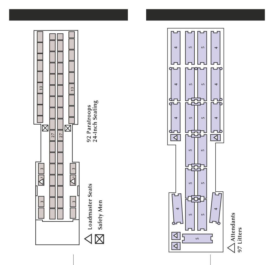
Paratroop Seating
Litters
18
19
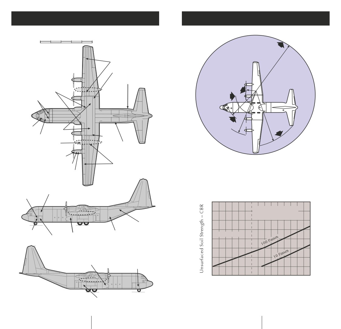
Ground Servicing Points
Ground Operations
0
10
20
30
40
50
FEET
Nose Wheel
60-deg.
Turn Radius
Wingtip Radius
89 ft 8 in.
Wing Fuel
Jack Point
Toilet
Main Gear Radius
Hydraulics
15 ft 4 in.
Urinals
Main Gear Radius
31 ft 4 in.
Horizontal
Nose Gear Radius
Tip Radius
Aux
46 ft 8 in.
73 ft 9 in.
Water
Tank
Fuel
Jack
Outer
Oxygen
Propeller
Point
Radius
External Tank Fuel
Hydraulic
65 ft
(Optional)
Propeller Oil
Engine Starter
Wing Fuel
Vertical Clearances
Minimum Space Required for
Engine Oil
Wingtip
12 ft
Turning is 179 Feet 4 Inches
Vertical Stabilizer Tip
38 ft 10 in.
With the Nose Gear Turned to
Inboard Propeller
6 ft
the Maximum of 60 Degrees at
Outboard Propeller
6 ft 8 in.
Taxi Speeds Under 5 Knots
Jack Points
Galley
Both Sides
10
Maximum Recommended
Weight for Marginal
Strength Airfields
8
Hydraulic
Electrical
Water
Pneumatic
CBR (Dirt, Grass)
(Left Side)
Oxygen
6
Flight Station
Cargo Compartment
4
Air-Conditioning
Air-Conditioning System
System
2
80
90
100
110
120
130
140
150
Gross Weight - 1,000 Pounds
Note
Number of Passes Is Based on Main Landing Gear Tire
Single-Point Refuel
Inflation Pressure for Marginal Strength Airfields.
A Pass Is Defined as One Landing and One Takeoff.
20
21
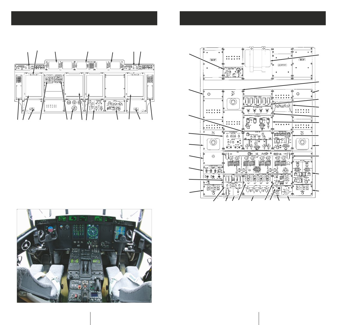
Flight Station Layouts
Flight Station Layouts
Instrument Panel
Overhead Panel
1
2
3
4
3
2
1
1
2
3
4
4
5
6
27
7
5
7 8
12
1110
77
9
8
7
6
5
8
26
9
1
Reference Set/Mode Select
7
Color Multipurpose
Panel (Two Places)
Display Unit (CMDU)
3
3
2
Inclinometer (Two Places)
8
Hydraulic Control Panel
3
Avionics Management Unit
9
Landing Gear/Landing
25
10
(Two Places)
Lights Panel
4
Communication/Navigation/
10
Flap and Trim
24
Electronic Circuit Breaker Panel
Indicator Panel
11
5
Mode Annunciator Panel
11
Standby Altimeter/
23
(Two Places)
Airspeed Indicator
6
Air Diverter Handle
12
Standby Attitude
22
12
(Two Places)
Indicator
21
20
19 18
17
16
15
14
13
1
Oxygen Regulator
15
ELT Panel
2
Oxygen Mask Stowage Box
16
APU Panel
3
Reading Light Control
17
Engine Start Panel
4
Headset Interface Unit
18
Fire Panel
5
Control Boost Panel
19
Prop Sync Panel
6
Console Light
20
ATCS Panel
7
Oil Cooler Flaps Panel
21
Propeller Control
8
Electrical Panel
Panel
9
Pressurization Panel
22
Pilot HUD Panel
10
Fuel Management Panel
23
FADEC Panel
11
Air Cond Panel
24
Exterior Lighting Panel
12
Co-pilot HUD Panel
25
Voice Recorder
13
Wipers Panel
Microphone Panel
14
Emergency Exit
26
Ice Protection Panel
Lights Extinguish
27
Bleed Air Panel
22
23
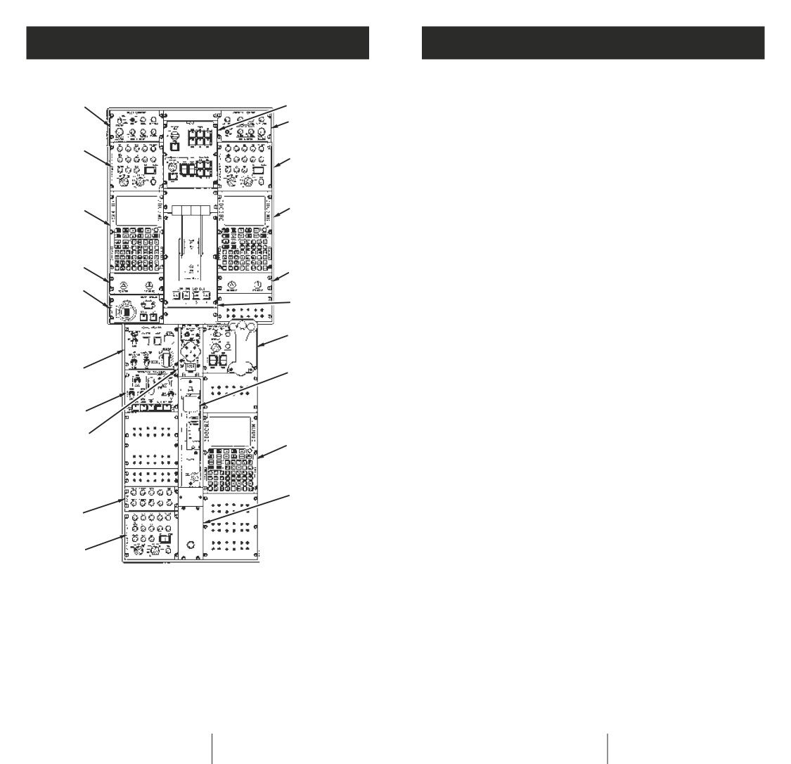
Flight Station Layouts
USAF Avionics Configuration
Center Console
Qty
1
2
Color Multipurpose Display Unit (CMDU)
4
3
Head-Up Display (HUD)
2
Global Digital Map Unit (GDMU)
1
4
Mission Computer
2
4
Avionic Management Unit (AMU)
2
Comm/Nav/Breaker Panel
1
Multichannel Dimming Unit
3
5
5
VHF AM/FM Comm Radio, AN/ARC-222 (MXF-626)
2
UHF Communication Radio, AN/ARC-164
2
HF Communication Radio, AN/ARC-190
2
6
HF Secure Voice, KYV-5 (ANDVT) (Group A)
2
6
VHF/UHF Secure Voice, KY-58 (Group A)
4
15
SATCOM (Group A)
1
7
UHF Satellite Terminal System (USTS) (Group A)
1
Intercommunication System
1
8
Embedded Global Positioning System/INS (EGI)
2
CNI-System Processor
2
14
9
CNI-Management Unit
3
Low-Power Color Radar, APN-241
1
13
Formation Station Keeping Equipment, SKE 2000
1
Distributed Air Data System
1
12
5
Radar Altimeter, HG9550
2
Tactical Air Navigation, AN/ARN-153
2
VHF Omnirange/Instrument Landing System/Marker
Beacon, AN/ARN-147 (One Marker Beacon)
2
10
Automatic Direction Finder, AN/ARN-149
2
11
1
UHF Direction Finder, DF-301E
1
Identification Friend or Foe, APX-119
1
4
Group A Provisions for 2nd IFF
1
Terrain Awareness and Warning System
1
1
Pilot Lighting Panel
9
Wing-Flaps Control
Group A Provisions for Second Enhanced
2
Radar Control Panel
Quadrant Panel
3
Co-pilot Lighting Panel
10
Headset Interface
Traffic Alert and Collision Avoidance Subsystem
1
4
Intercommunications System
Unit Panel
Digital Autopilot/Flight Director
2
Control Panel (Three Places)
11
Intercommunications
Missile Warning System, AN/AAR-47 (Group A)
1
5
Communication/Navigation/
System Monitor Panel
Countermeasures Dispensing System,
Identification Management
12
Trim Panel
AN/ALE-47 (Group A)
1
Unit (Three Places)
13
Defensive Systems Panel
Radar Warning Receiver, AN/ALR-56M (Group A)
1
6
Remote Heading and Course
14
Aerial Delivery Panel
Ground Proximity Warning System
1
Selector (Two Places)
15
Automatic Flight Control
7
Throttle Quadrant Assembly
System Panel
Integrated Precision Radar Approach System
1
8
Cursor Control Panel
24
25

Major Systems
Major Systems
ELECTRICAL
ENVIRONMENTAL CONTROL SYSTEM
• The electrical system includes four regulated
• The aircraft’s environmental control system (ECS)
transformer rectifier units, five AC generators,
is capable of stabilizing the cockpit environment
controls, and conversion equipment needed
from a heat soak temperature condition at external
to satisfy and control the diversified power
ambient temperature of +120°F (+49°C) to
requirements of the various electrical and
+84°F (+28.8°C) within 30 minutes from cooling
electronic equipment and other systems.
operation ECS start. The ECS is capable of
Secondary distribution uses electronic and
increasing the cabin average temperature from
electromechanical circuit breakers.
-22°F (-30°C) to +41°F (+5°C) within 20 minutes.
• Four 40/50-kVA oil-cooled, three-phase AC
• Cargo-floor heating is accomplished by using hot
generators constitute the primary AC power source.
air circulating through an underfloor manifold.
Each engine-driven generator has an overtorque
• A forced-air cooling system is provided for the
shaft disconnect and an individual generator
flight-station displays and certain rack-mounted
control unit. A fifth 40/50-kVA air-cooled, three-
avionics and electrical equipment.
phase AC generator is mounted on the auxiliary
• A system for pressurizing the flight station
power unit as an additional AC power source.
and cargo compartment is supplied by engine
• Two 24-volt, 42-ampere-hour (beginning of life),
compressor bleed air. This electronically controlled
sealed, lead acid, and maintenance-free batteries
pneumatic system is capable of maintaining
are installed in a battery compartment in the lower
a maximum of 8,000-foot cabin altitude at
left forward fuselage. A control switch in the flight
32,200-foot flight altitude. The aircraft is
station disconnects the batteries from the electrical
pressurized and depressurized in accordance with
system. With fully charged batteries, sufficient
a preprogrammed schedule and under rate control
battery power is available to operate standby
while in the automatic mode. A separate backup
instruments and other flight-critical components for
manual control of the pressurization system
approximately 30 minutes after complete loss of
provides outflow valve operation in case of a
primary aircraft power. When required, one battery
failure in the automatic system.
can provide electrical power for APU starting.
• Four regulated 200-ampere transformer rectifiers
FUEL SYSTEM
convert AC power to DC power. Two 1-kVA
• The fuel system uses a common cross-ship
inverters provide uninterruptable electrical
manifold that serves as a refueling system, a fuel
power for the essential avionics bus and the
supply crossfeed, a direct feed system, a ground
main avionics bus.
defueling system, and a fuel jettisoning system.
• Regulated power supplies (RPSs) provide filtered
The fuel system consists of tanks, pumps, piping,
and regulated DC power to the flight station
valves, flowmeters, strainers, and quantity
consoles. The RPS is powered by two independent
gage units.
28-VDC power sources.
• Fuel system design and performance is based on
the use of fuel conforming to JP-8 (MIL-T-83133).
• The system is compatible with JP-4, JP-5, Jet A,
Jet A-1, and Jet B fuels with or without anti-icing
26
27
Major Systems
Major Systems
additive. Deviations and flight restrictions are
• The auxiliary system furnishes hydraulic power for
required for use of some fuels other than JP-8.
normal ramp and cargo door operation. The system
• Group A provisions are provided on the lower side
also provides pressure for wheel brake operation,
of each outer wing at outer-wing station 81.0 for
NLG extension, and down lock in the event of
optional installation of pylons and tanks. When the
utility system failure.
tanks/pylons are installed, each tank has a usable
fuel capacity of 1,379 U.S. gallons (9,377 pounds
ENHANCED CARGO HANDLING SYSTEM (ECHS)
or 18,754 pounds per aircraft).
• The ECHS allows the load-crew to control all
• The aircraft has the capability for single-point
aspects of logistic and airdrop operations by
refueling (SPR) which is integrated into the
providing computer-controlled event sequencing
fuel management system and controlled via
of all onload, offload, airdrop, and emergency
the fuel management panel. Refueling quantities
functions from a single location. The multifunction
can be set for each tank. A manual over-the-wing
control/display, located at the loadmaster position,
fuel-filler cap is installed in each main tank.
provides control and display of all ECHS functions.
• Defueling normally is through the ground
The aircraft is capable of performing aerial delivery
single-point refueling system using the fuel
missions using manual, computer, or combined
boost and dump pumps to supply pressure.
computer- and manual-controlled modes.
Defuel quantities can be set for each tank at
the fuel management panel.
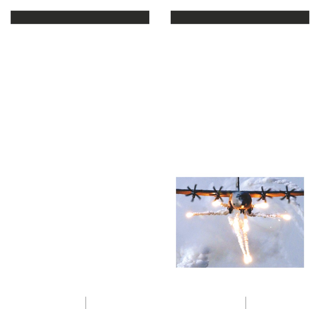
DEFENSIVE SYSTEMS
• Fuel dump controls are located on the fuel
• Missile Warning System, AN/AAR-47
management panel located in the flight station.
• Countermeasures Dispensing System, AN/ALE-47
• Receiver P3I provisions are available for
• Radar Warning Receiver, AN/ALR-56M
aerial refueling.
• Tanker P3I provisions are included.
HYDRAULIC SYSTEMS
• Three separate hydraulic systems are controlled
by engine-mounted or electrically driven pumps.
The pumps for the booster system are mounted on
engines three and four, and the pumps for the
utility system are mounted on engines one and two.
The auxiliary system is powered by an electrically
driven pump located in the aft fuselage. Normal
operating pressure is 3,000 pounds per square inch.
• The booster system operates one-half of each
control surface actuator.
• The utility system operates the landing gear
(including doors and steering), wing flaps,
wheel brakes, and one-half of each control
surface actuator.
28
29
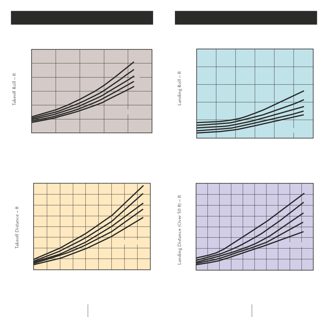
Performance
Performance
MAXIMUM EFFORT TAKEOFF ROLL
MAXIMUM EFFORT LANDING ROLL
(Standard Day)
(Four Engines/100 Percent Flaps/Standard Day)
6,000
3,500
8
5,000
3,000
6
4,000
4
2
2,500
0
3,000
8
6
2,000
2,000
4
2
Altitude - 1,000 ft
0
1,000
1,500
Altitude - 1,000 ft
0
80
100
120
140
160
180
1,000
80
90
100
110
120
130
140
Gross Weight - 1,000 lb
Gross Weight - 1,000 lb
NORMAL TAKEOFF DISTANCE (Over 50 Feet)
Takeoff Distance
Over 50-Foot Obstacle
NORMAL LANDING DISTANCE (Over 50 Feet)
(100 Percent Flaps/Standard Day)
(Four Engines/50 Percent Flaps/Standard Day)
9,000
6,000
8
6
8
8,000
5,500
4
6
7,000
5,000
2
4
6,000
4,500
0
2
5,000
4,000
0
4,000
3,500
Altitude - 1,000 ft
Altitude - 1,000 ft
3,000
3,000
2,000
2,500
1,000
2,000
80
90
100
110
120
130
140
150
160 170
80
90
100 110
120
130
140
150
160 170 180
Gross Weight - 1,000 lb
Gross Weight - 1,000 lb
30
31
Performance
World Records
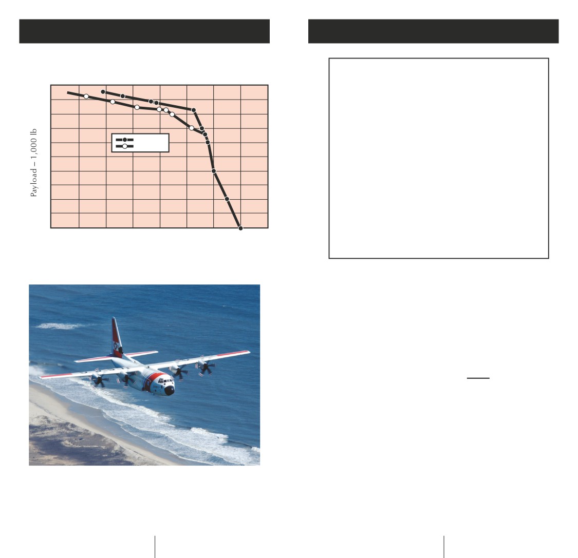
PAYLOAD RANGE
Standard Day, MIL-C-5011A Reserves (Foam in Tanks)
54 World Records
50
All in production-standard,
unmodified aircraft
40
These flights demonstrate that the C-130J can:
175,000 lb
• Carry a useful payload quickly
30
164,000 lb
over typical mission distance.
• Get in and out of short fields
20
quickly and carry useful payload.
• Quickly climb to altitude with a
10
significant payload.
• Be flown a strategic distance
0
quickly without external tanks
0
1,000
2,000
3,000
4,000
or stopping to refuel.
Range - n.mi
USAF Configuration
Wing Relief Fuel
LOCKHEED MARTIN C-130J
CLAIMS 54 WORLD RECORDS
The following records have been certified as
world records:
Class C-1.N Turboprop, Group II, Heavy Airplanes
(132,276 to 176,368 lb)
Records broken
15
Records set
6
Total
21
Closed Circuit (Speed and Distance)
NEW RECORD USA, 396.17 mph; Lockheed Martin
C-130J, 4/20/99
Breaks old record by 8 percent while
carrying twice the payload
BREAKS these existing records:
1,000 km speed with following
payloads: 0 kg; 1,000 kg; 2,000 kg;
5,000 kg; 10,000 kg
32
33

World Records
World Records
ESTABLISHES these records:
Closed Circuit
1,000 km speed with 15,000 and
NEW RECORD USA, 371.6 mph; Lockheed Martin
20,000 kg payloads
C-130J, 5/14/99
NEW RECORD USA, 394.87 mph; Lockheed Martin
ESTABLISHES these records:
C-130J, 4/20/99
1,000 km speed with following
Breaks old record by 16 percent
payloads: 0 kg; 1,000 kg; 2,000 kg;
while carrying twice the payload
5,000 kg; 10,000 kg
BREAKS these existing records:
NEW RECORD USA, 371.96 mph, Arlen Rens (pilot),
2,000 km speed with following
Lyle Schaefer (co-pilot),
payloads: 0 kg; 1,000 kg; 2,000 kg;
Lockheed Martin C-130J, 5/14/99
5,000 kg; 10,000 kg
ESTABLISHES these records:
ESTABLISHES these records:
2,000 km speed with following
2,000 km speed with 15,000
payloads: 0 kg; 1,000 kg; 2,000 kg;
and 20,000 kg payloads
5,000 kg; 10,000 kg
Altitude
NEW RECORD USA, 22,300 lb; Lockheed Martin
C-130J, 5/14/99
NEW RECORD USA, 36,560 feet; Lockheed Martin
C-130J, 4/20/99
BREAKS this existing record:
Greatest load to 2,000 meters
Breaks old record by 18 percent
while carrying twice the payload
NEW RECORD USA, 40,386 feet; Lockheed Martin
C-130J, 5/14/99
BREAKS these existing records:
Altitude with following payloads:
ESTABLISHES these records:
0 kg; 1,000 kg; 2,000 kg; 5,000 kg;
Absolute altitude with following
10,000 kg
payloads: 0 kg; 1,000 kg; 2,000 kg;
5,000 kg; 10,000 kg
ESTABLISHES these records: Altitude
with 15,000 and 10,000 kg payloads
NEW RECORD USA, 39,052 feet; Lockheed Martin
C-130J, 5/14/99
The following short takeoff and landing (STOL)
records have been certified as U.S. national records.
ESTABLISHES this record:
Greatest altitude in horizontal
STOL Aircraft, Class N, Group II, Turboprop
flight (Note: Must hold this altitude
Records broken
1
for a minimum of 90 seconds)
Records set
28
Time-to-Climb
Total
29
NEW RECORD USA, 3 min 49 sec; Lockheed Martin
C-130J, 5/14/99
34
35
World Records
ESTABLISHES these records:
To 3,000 meters with following
payloads: 1,000 kg; 2,000 kg;
5,000 kg; 10,000 kg
NEW RECORD USA, 8 min 0 sec; Lockheed Martin
C-130J, 5/14/99
ESTABLISHES these records:
Time-to-climb to 6,000 meters
with following payloads: 1,000 kg;
2,000 kg; 5,000 kg; 10,000 kg
NEW RECORD USA, 15 min 12 sec;
Lockheed Martin C-130J, 5/14/99
ESTABLISHES these records:
Time-to-climb to 9,000 meters
with following payloads: 1,000 kg;
2,000 kg; 5,000 kg; 10,000 kg
Speed Over a Recognized Course
NEW RECORD USA, 413.99 mph; Lockheed Martin
The information provided herein represents
C-130J, 12/7-8/99
the opinions of Lockheed Martin Aeronautics
Company. It does not constitute an offer
ESTABLISHES these records:
to sell and is not warranted or guaranteed.
Speed over a recognized course,
Specifications and performance of individual
unlimited class; speed over a
aircraft may vary and will be governed by the
recognized course, class C-1.N
terms and conditions of other documents.
Duration: 10 hours 58 minutes
Lockheed Martin Aeronautics Company is not
14 seconds
responsible for the accuracy or reliability of any
opinion, advice or statement made herein and
NEW RECORD USA, 417 mph; Lockheed Martin
will not be liable for any damages of any kind,
C-130J, 2/12-13/00
in any way relating to this information or its use.
ESTABLISHES these records:
Speed over a recognized course
with 34,000 pounds of payload,
unlimited class; speed over a
recognized course with 34,000
pounds of payload, class C-1.N
Duration: 9 hours 31 minutes
Lockheed Martin Aeronautics Company
Marietta, Georgia
36
37