Siemens SIMATIC Industrial Software Engineering Tools TS Adapter II. Manual (2008)
147HPreface
SIMATIC Industrial Software Engineering Tools TSdapterI
Properties of the
1
2
Scope of delivery
SIMATIC
3
Requirements for operation
Industrial Software
Hardware configuration
Engineering Tools
4
of the TS Adapter II
Working with the
5
Manual
TS Adapter II on the
6
MPI/DP/PPI network
7
Firmware update
8
Error diagnostics
A
Appendix
06/2008
A5E00272728-03
Preface
Purpose of this manual
This manual provides a complete overview of the TS Adapter II and supports you in the
installation and commissioning of the software and hardware. It explains the requirements for
operation and hardware installation, and how to connect the adapter to MPI/DP/PPI
networks.
It is intended for programmers and persons involved in configuring, commissioning, and
servicing of automation systems.
Required basic knowledge
This manual requires general knowledge of automation engineering.
You also require knowledge of the use of computers or PC-based equipment (such as
programming devices) operating on Windows 2000 and Windows XP platforms.
Scope of this manual
This manual applies to the TS Adapter II product.
Network approval for Europe
The TS Adapter II-Modem is compliant with the European Standard TBR 21.
The TS Adapter II-ISDN is compliant with the telecommunications registration TBR 3.
Network approval for the USA
This equipment complies with ACTA.
Network approval for Canada
The Industry Canada (ic) label identifies certified equipment.
3
Preface
Additional support
If you have any questions relating to the products described in this manual, and do not find
the answers in this documentation, please contact your Siemens partner at our local offices.
You will find information on who to contact at:
A signpost to the documentation of the various SIMATIC products and systems is available
at:
You will find the online catalog and order system at:
Training center
We offer a range of courses to help you to get started with the SIMATIC S7 automation
system. Please contact your regional training center, or the central training center in
D 90327 Nuremberg, Germany.
Telephone: +49 (911) 895-3200.
Internet: http://www.sitrain.com
Technical support
How to contact Technical Support for all Industry Automation products
● Using the Web form for a support request
● Telephone: + 49 180 5050 222
● Fax: + 49 180 5050 223
Additional information about our technical support is available in the Internet at
Service & Support on the Internet
In addition to our documentation, we offer a comprehensive online knowledge base on the
Internet at:
There you will find:
● The newsletter, which constantly provides you with up-to-date information on your
products.
● Relevant documentation for your application, which you can access via the search
function in Product Support
● A forum for worldwide knowledge exchange for users and experts.
● Your local partner of Industry onsite.
● Information about repairs, spare parts and consulting.
4
Table of contents
Preface
3
1
Properties of the TS Adapter II
7
1.1
Properties
7
1.2
Function
7
1.3
Performance features
9
2
Scope of delivery
11
3
Requirements for operation
13
3.1
Software requirements
13
3.2
Hardware Requirements
13
3.3
Installation
14
3.3.1
Installation on mounting rail
15
3.3.2
Installation on a DIN rail
16
4
Hardware configuration of the TS Adapter II
19
4.1
Connections
19
4.2
LEDs on the TS Adapter II
21
4.3
Power supply
23
4.4
MPI/DP interface
24
4.5
USB interface
26
4.6
RS232 interface
27
4.7
Power plug for power supply
28
4.8
Modem interfaces
30
4.8.1
TS Adapter II-Modem variant
30
4.8.2
Technical specifications of the analog modem
31
4.8.3
TS Adapter II-ISDN variant
32
4.8.4
Technical specifications of the ISDN terminal adapter
34
5
Working with the TS Adapter II
35
5.1
Safety notices
35
5.2
Installing the software
35
5.3
Setting the PG/PC Interface
36
5.4
Connecting the TS Adapter II
37
6
TS Adapter II on the MPI/DP/PPI network
41
6.1
General information
41
6.2
Use in a stand-alone system
41
5
Table of contents
6.3
Use on networked system
42
6.3.1
Connection to networked S7 systems
42
6.3.2
Connection in the ring
42
7
Firmware update
43
8
Error diagnostics
45
A Appendix
47
A.1
Standards, Approvals, Certificates, Guidelines, Labels, and Declarations
47
A.2
Customer Information for ACTA
52
A.3
General technical specifications
53
A.3.1
Electromagnetic compatibility
55
A.3.2
Shipping and storage conditions
57
A.3.3
Mechanical and climatic environmental conditions for operation of the TS Adapter II
57
A.3.4
Specification of Insulation Testing, Protection Class and Degree of Protection /Test
Voltage
59
Index
61
Tables
Table 1-1
Bus profiles and baud rates
9
Table A-1
Pulse-shaped Interference
55
Table A-2
Sinusoidal Interference
56
Table A-3
Shipping and storage conditions for modules
57
Table A-4
Mechanical environmental conditions
58
Table A-5
Test for mechanical environmental conditions
58
Table A-6
Climatic environmental conditions
59
Figures
Figure 1-1
TS Adapter II with direct connection
8
Figure 1-2
TS Adapter II with modem connection
8
Figure 3-1
Rear panel of the TS Adapter II
14
Figure 3-2
Slide for installing the TS Adapter II on a DIN rail
16
Figure 3-3
Installing TS Adapter II
16
Figure 3-4
Minimum clearance
17
Figure 4-1
TS Adapter II-Modem
19
Figure 4-2
TS Adapter II-ISDN
20
Figure 4-3
LEDs of the TS Adapter II
21
Figure 4-4
MPI cable, 0.8 m with 9-pin sub D connectors
25
Figure 4-5
MPI cable (0.8 m)
25
Figure 5-1
Front view with reset button
39
Figure 6-1
Connection to a stand-alone system
41
6
Properties of the TS Adapter II
1
1.1
Properties
Overview
The USB connection of the TS Adapter II is compatible with USB V1.1 and complies with the
specifications for a "Low-Powered" USB device. The TS Adapter II supports hibernate mode.
When used in an S7-300 system, the TS Adapter II does not loop through the I/O bus.
Therefore, the TS Adapter II should preferably be mounted in the last position on the rack.
1.2
Function
Connections
● Modem connection: The TS Adapter II allows a component running on a PC (e.g.,
STEP 7) to access automation components (S7 and C7) on an MPI/DP/PPI bus by
means of the telephone network. The TeleService application is required to establish a
remote connection.
● Direct connection: With direct connection, the TS Adapter II allows data exchange
between the programming device or PC and an S7/C7 system via the
Universal Serial Bus (USB). The TS Adapter II with direct connection corresponds
functionally to a PC Adapter USB.
The TS Adapter II can be assigned with modem connection (with an established remote
connection) and with direct connection. The TeleService application is used to assign
parameters.
7
Properties of the TS Adapter II
1.2 Function
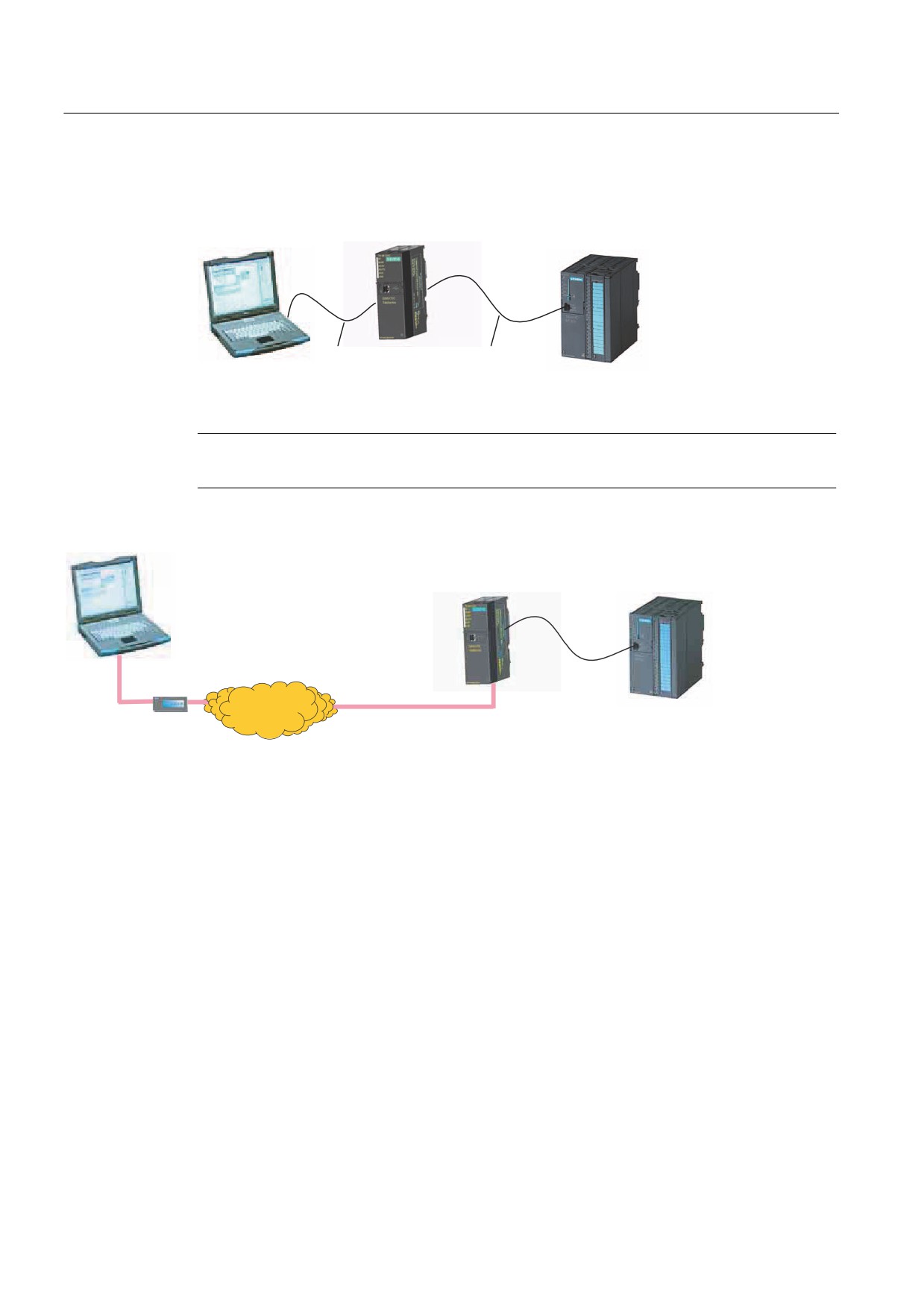
The following figures show the TS Adapter II-Modem with direct connection and with modem
connection:
76
$GDSWHU ,, 0RGHP
86%
03,
Figure 1-1
TS Adapter II with direct connection
Note
You can operate only one TS Adapter II on a PC.
76
$GDSWHU ,, 0RGHP
3KRQH QHWZRUN
03,
0RGHP
$QDORJ SKRQH FDEOH
Figure 1-2
TS Adapter II with modem connection
8

Properties of the TS Adapter II
1.3 Performance features
1.3
Performance features
You can operate the TS Adapter II on MPI networks, PROFIBUS networks, and
homogeneous PPI networks. The TS Adapter II corresponds basically to a PC Adapter USB.
Baud rates and bus profiles
The following table shows the baud rates supported by the TS Adapter II on various network
types.
Table 1-1
Bus profiles and baud rates
Baud rate
MPI
PPI
PROFIBUS
DP
Standard
Universal
User-
defined
9,600 bps
-
✔
✔
✔
✔
✔
19,200 bps
✔
✔
✔
✔
✔
✔
45,450 bps
-
-
✔
✔
-
✔
93,750 bps
-
-
✔
✔
✔
✔
187,500 bps
✔
✔
✔
✔
✔
✔
500 kbps
-
-
✔
✔
✔
✔
1500 kbps
✔
-
✔
✔
✔
✔
3 Mbps
✔
-
✔
✔
-
✔
6 Mbps
✔
-
✔
✔
-
✔
12 Mbps
✔
-
✔
✔
-
✔
Performance features of the TS Adapter II
● Connection to PC via USB
● Automatic bus profile detection
● Up to 16 communication connections, including a maximum of 4 slaves
(DP/T connections)
● Support for routing
● Support for "PG_DIAL", "AS_DIAL", "SMS_SEND" function blocks
● External voltage supply possible
● A DIN rail mounting is also integrated.
9
Properties of the TS Adapter II
1.3 Performance features
10

Scope of delivery
2
Overview
The scope of delivery of both SIMATIC TS Adapter II variants includes:
● "SIMATIC TeleService Edition" CD with software and documentation
● USB cable (5 m)
●
24 V power plug
● MPI cable (0.8 m)
● Slide for DIN rail mounting
You can use the MPI cable to connect the TS Adapter II to MPI networks, homogeneous PPI
networks, or PROFIBUS (DP) networks.
Additionally for the modem variant:
● Analog phone cable with 2 RJ12 connectors (3 m)
● TAE connector (Europe)
Additionally for the ISDN variant:
● ISDN phone cable with 2 RJ45 connectors (3 m)
Spare parts
Designation
Order No.
MPI cable, 0.8 m
A5E00228477
USB cable, 5 m
A5E00276884
Analog phone cable
A5E00243688
ISDN phone cable
A5E00243651
TAE connector
A5E00243701
24 V power plug
A5E00073529
Slide for DIN rail mounting
A5E00213070
The spare parts can be ordered from your local Siemens representative.
11
Scope of delivery
12
Requirements for operation
3
3.1
Software requirements
Overview
For working with the TS Adapter II, you need a PC with an MS Windows operating system
and the software (device driver) for the TS Adapter II.
The list of supported operating systems is included in the latest Readme file for the
TS Adapter II software.
To assign parameters and to establish a remote connection, you will need:
● SIMATIC TeleService
TeleService V6.0 or higher is required for parameter assignment of the TS Adapter II.
Prior versions can be used to establish a remote connection and, if necessary, to log on
to the TS Adapter II.
● Teleservice V6.0 SP1 is required to operate the TS Adapter II ISDN in the USA or
Canada.
And a
● SIMATIC SW package that accesses via MPI communication (e.g., STEP 7)
The STEP 7 Micro/Win32 SW package is also required to operate the TS Adapter II on a PPI
network.
3.2
Hardware Requirements
Overview
To work with the TS Adapter II, you will need a PC with one of the following hardware items:
● You will need a PC with a USB interface and CD-ROM drive.
● To comply with the installation requirements of UL for the TS Adapter II-ISDN, you must
use a
UL-listed NTBA (Network Terminal Basic Adapter).
● To comply with the UL requirements for the TS Adapter II-Modem, you must use a UL
DUXR phone cable (comprising a cable and connectors) with AWG 26 cable cross-
section. The supplied cable fulfills this requirement.
13
Requirements for operation
3.3 Installation
3.3
Installation
Types of installation
You can install the TS Adapter II as follows:
● On the mounting rail of the S7-300 (see section "Installation on mounting rail"). Make sure
that you use the lost slot of the mounting rail since the TS Adapter II does not loop
through the signals of the I/O bus, or
● On the DIN rail (see section "Installation on DIN rail").
WARNING
The mounting rail or DIN rail on which the TS Adapter II is installed must be grounded.
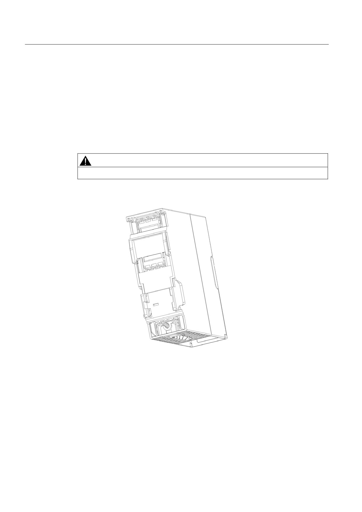
Rear panel of the TS Adapter II:
Figure 3-1
Rear panel of the TS Adapter II
14
Requirements for operation
3.3 Installation
3.3.1
Installation on mounting rail
Procedure
The various module installation steps are explained below.
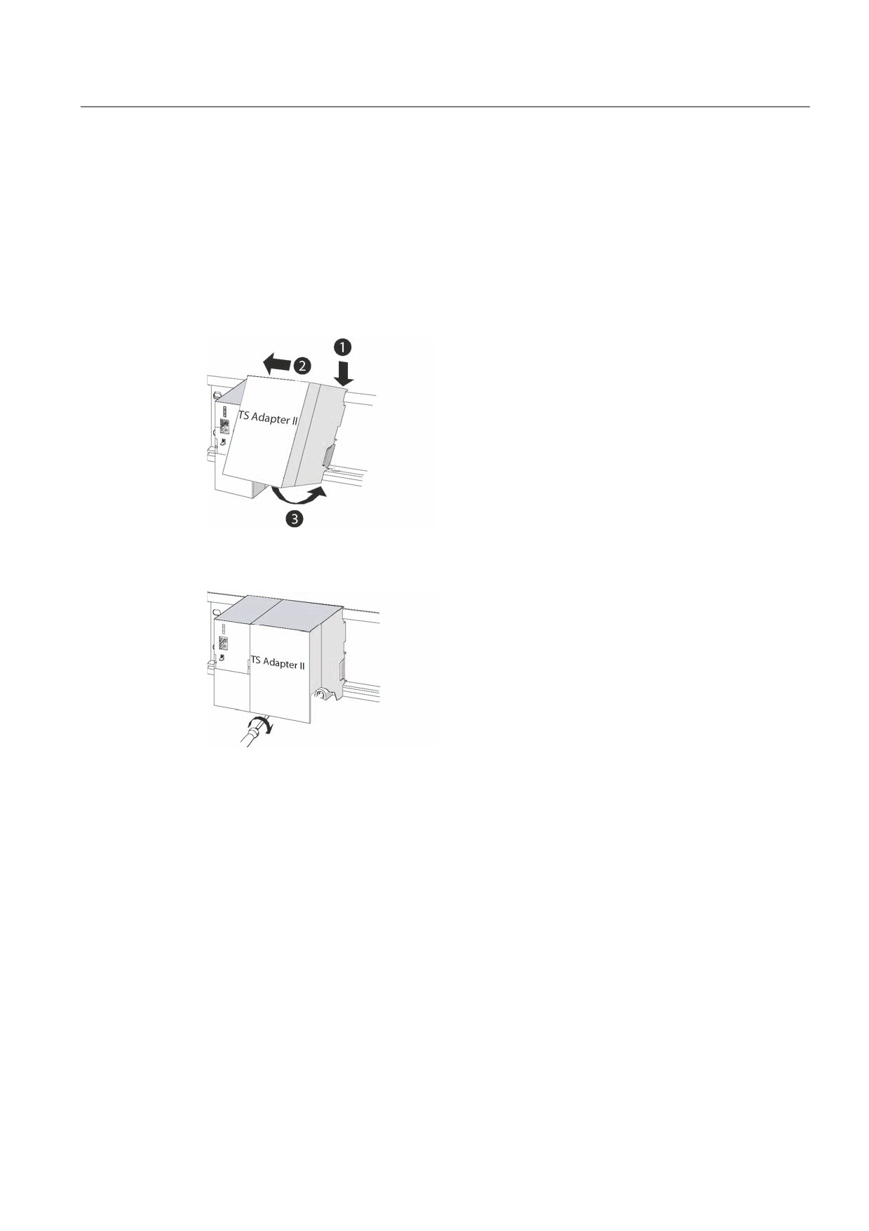
1. Place the TS Adapter II at the of the profile rail. Unlike S7-300 modules, the TS Adapter II
does not require a bus connector. Hook the TS Adapter II onto the rail (1), slide it over
until it reaches the module on the left (2), and swing it down into place (3).
2. Hand-tighten the screws on the TS Adapter II.
15
Requirements for operation
3.3 Installation
3.3.2
Installation on a DIN rail
Requirement
The DIN rail is mounted.
Tools required: 3-mm screwdriver
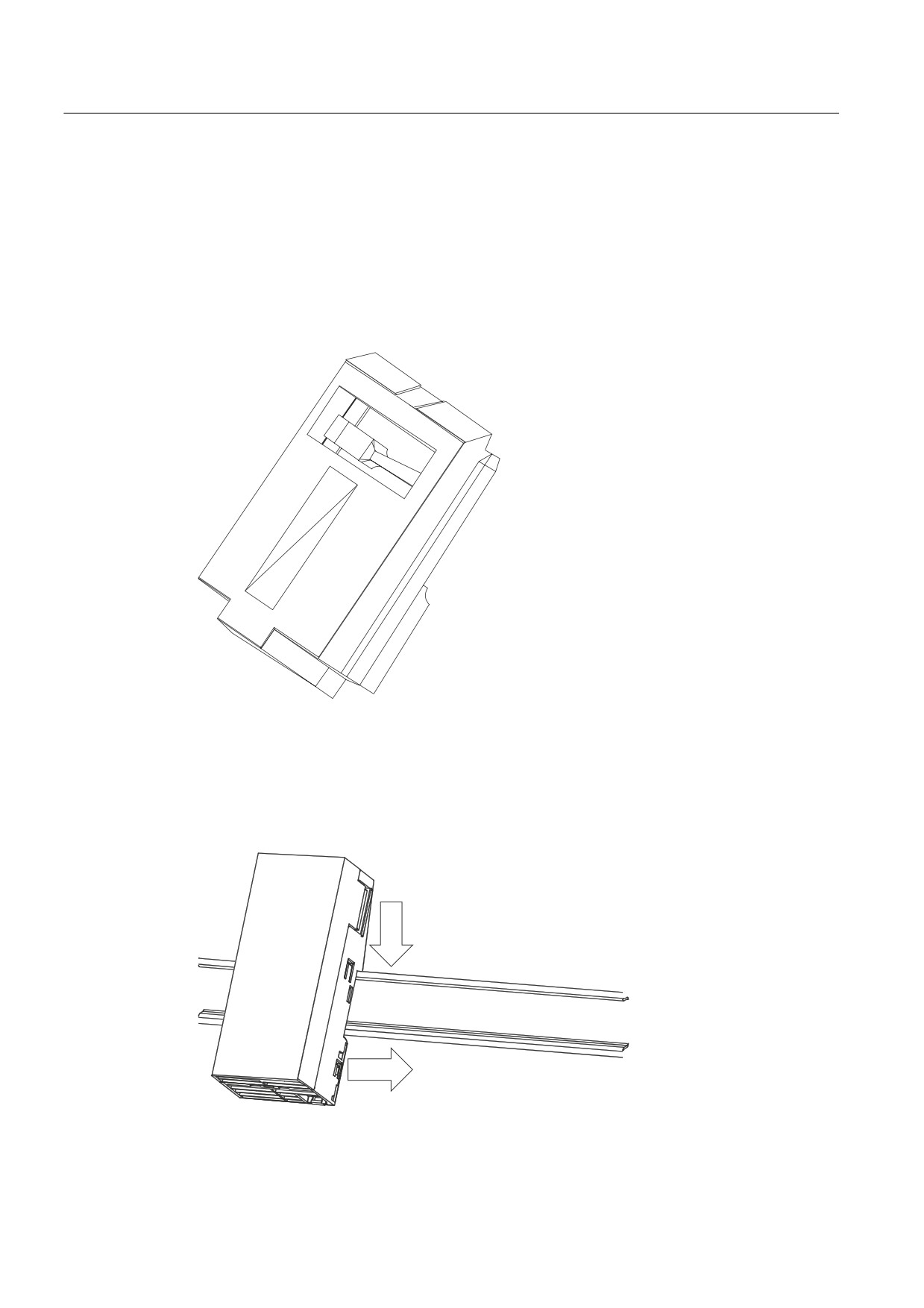
The enclosed slide must be inserted into the rear panel of the TS Adapter II from below.
Figure 3-2
Slide for installing the TS Adapter II on a DIN rail
Installing TS Adapter II
1. Hook the TS Adapter II onto the DIN rail.
2. Swivel the TS Adapter II back until the slide engages audibly.
Figure 3-3
Installing TS Adapter II
16
Requirements for operation
3.3 Installation
Uninstalling TS Adapter II
1. You can see the bottom end of the slide on the underside of the TS Adapter II. Using a
screwdriver, press against the slide in the direction of the DIN rail and pull the slide
downward, thus loosening the engagement mechanism.
2. Swivel the TS Adapter II forward out of the DIN rail.
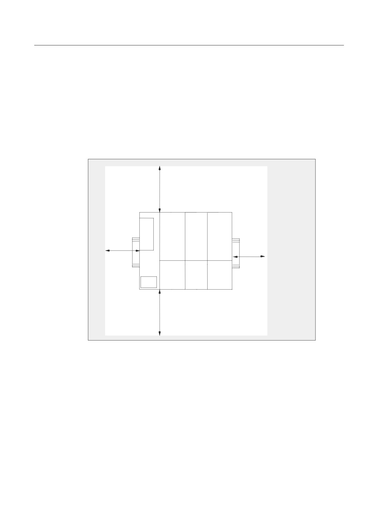
Minimum clearances for installation, wiring, and ventilation
When installing the TS Adapter II in a housing, ensure that the distance to the lid of the
housing or the front door is at least 2 mm.
PP
PP
PP
PP
Figure 3-4
Minimum clearance
17
Requirements for operation
3.3 Installation
18
Hardware configuration of the TS Adapter II
4
4.1
Connections
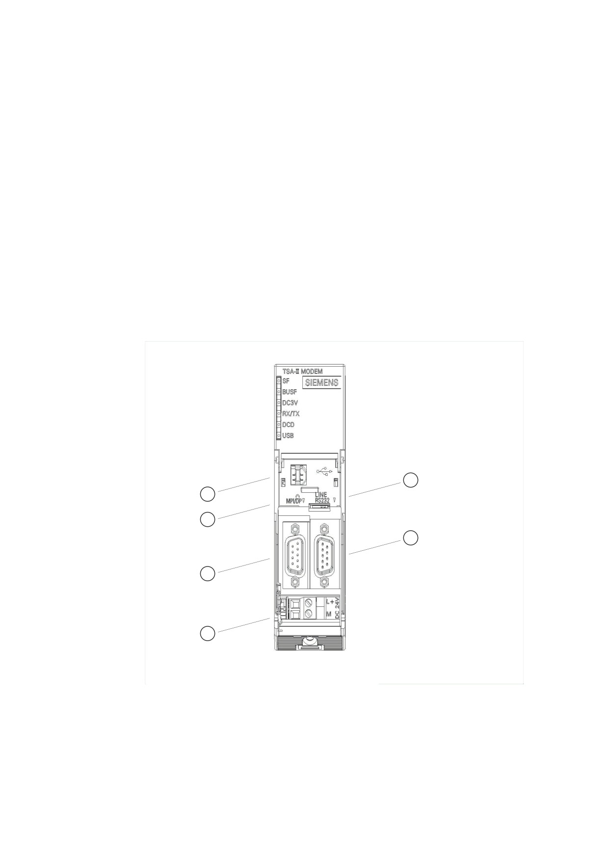
Below are two figures showing the different adapters and their respective connections.
TS Adapter II-Modem
The TS Adapter II-Modem is equipped with the following connections:
Figure 4-1
TS Adapter II-Modem
① USB interface
② Reset button
19
Hardware configuration of the TS Adapter II
4.1 Connections
③ MPI/DP socket
④ Power plug for power supply
⑤ RJ12 MODEM interface
⑥ RS232 serial interface
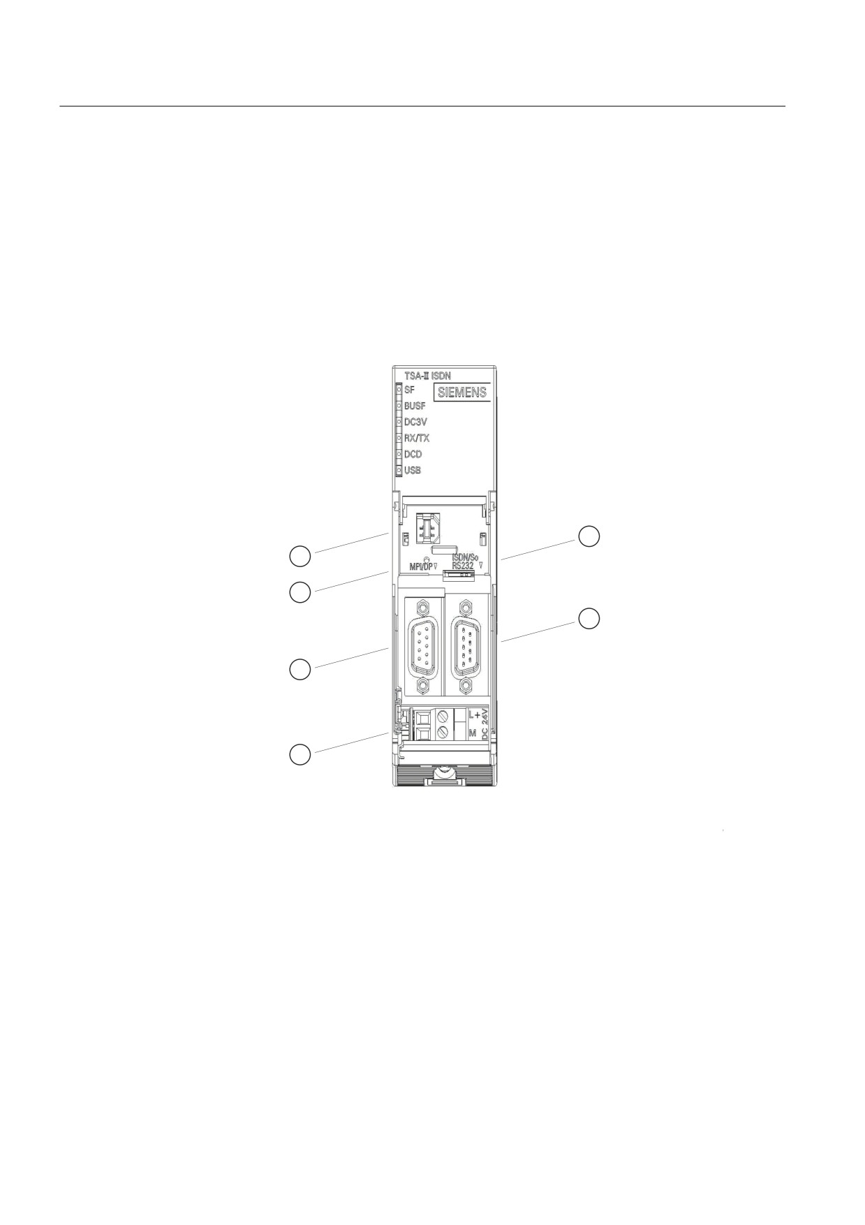
TS Adapter II-ISDN
The TS Adapter II-ISDN is equipped with the following connections:
Figure 4-2
TS Adapter II-ISDN
① USB interface
② Reset button
③ MPI/DP socket
④ Power plug for power supply
⑤ RJ45 ISDN interface
⑥ RS232 serial interface
20
Hardware configuration of the TS Adapter II
4.2 LEDs on the TS Adapter II
4.2
LEDs on the TS Adapter II
Overview
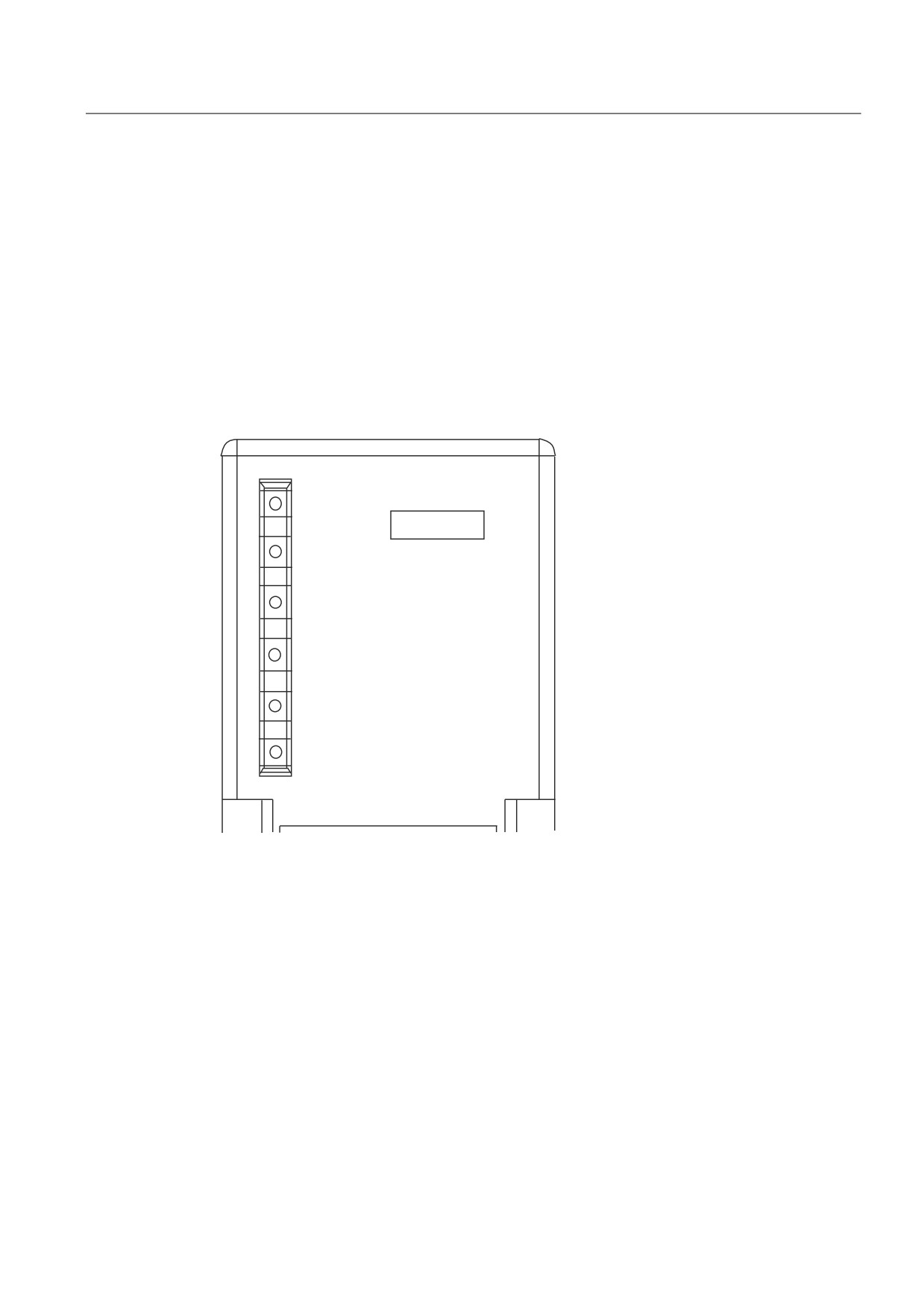
The TS Adapter II is equipped with the following LEDs:
●
3V operating voltage
● Bus fault
● USB
● DCD
● RX/TX
76$ ,, 02'(0
6)
6,(0(16
%86)
'& 9
5; 7;
'&'
86%
Figure 4-3
LEDs of the TS Adapter II
SF
Group error
BUSF Bus fault
DC3V
3V operating voltage
RX/TX RX/TX
DCD DCD
USB
USB
Startup characteristics
All LEDs are switched on when power is restored. After a few seconds, the LEDs are set
according to the current operating state.
21

Hardware configuration of the TS Adapter II
4.2 LEDs on the TS Adapter II
The LEDs on the TS Adapter II have the following meaning:
Designation
Color
Meaning
SF
Red
Group error:
Lights up when the TS Adapter II detects an error situation on the
modem interface or the MPI/DP interface.
This LED also is also lit during a firmware download operation.
BUSF
Red
Bus fault:
This LED is switched off when the TSP Adapter II has been
incorporated in the MPI/DP network without errors.
It is lit if the TS Adapter II is not incorporated in the MPI/DP network
due to faulty network parameters or a missing MPI connection.
DC3V
Green
Lights up when the TS Adapter II is supplied with the necessary
operating voltage.
RX/TX
Green
Indicates data traffic between the TS Adapter II and the (integrated)
modem. The LED flickers during data transmission.
DCD
Yellow
Lights up when a remote connection is established via the modem
interface of the TS Adapter II.
The LED is off when there is no remote connection.
After reset using the Reset key: Flashes 3 times when the default
parameter assignment has been applied.
USB
Green
Lights up when the TS Adapter II is connected to the USB and the
operating system of your PC is in normal mode. This LED is off when
the PC is in standby or idle mode.
The LED flickers during data transmission.
The indication of possible error states is described in section "Error Diagnostics".
22
Hardware configuration of the TS Adapter II
4.3 Power supply
4.3
Power supply
The automation system supplies power to the TS Adapter II via the supplied MPI cable or the
power socket for an external power supply.
The TS Adapter II requires only 24 V voltage (see appendix "General technical
specifications").
No current is drawn from the USB interface.
DANGER
Only connect the TS Adapter II to devices with power supplies with limited power (SELV).
The MPI/DP interface is electrically isolated. Therefore, the TS Adapter II can also be
operated directly on ungrounded mounted S7 and C7 systems.
The power supply makes available electrically-isolated internal voltages from the 24 V DC of
the MPI/DP interface or an external infeed. Approximately 2 W of power are supplied.
23
Hardware configuration of the TS Adapter II
4.4 MPI/DP interface
4.4
MPI/DP interface
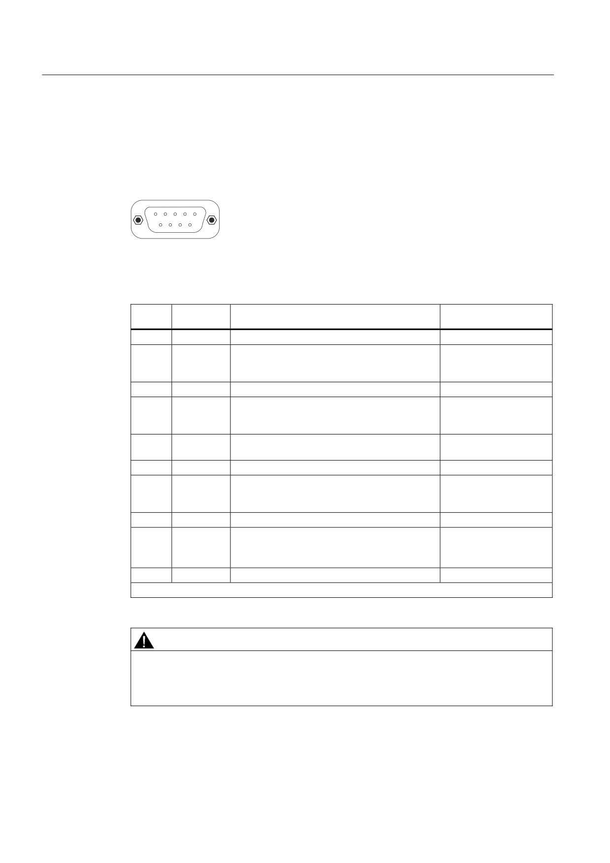
Connector assignment
The MPI/DP socket has the following pinout:
Signal description
Pin. No.
Short
Meaning
Input/
description
output
1
NC
Not connected
-
2
M24V
For 0 V line of the 24 V supply; supplies the
Input
adapter electronics via a DC/DC converter (PC
potential area)
3
LTG_B
Data line B
Input/output
4
RTS_AS
RTS_AS, control signal for receive data stream.
Input
The signal is "1" when the directly connected AS
is sending
5
M5V
Reference potential of MPI/DP interface for the
Input
RTS_AS and RTS_PG signals
6
P5V
For supplying power to terminating resistors
Output
7
P24V
For +24V line of the 24 V supply; supplies the
Input
adapter electronics via a DC/DC converter (PC
potential area)
8
LTG_A
Data line A
Input/output
9
RTS_PG
RTS output signal of the adapter. The signal is
Output
"1" when the adapter is sending.
The signal is not contained in the MPI cable.
Shield
On connector casing*
-
* The shield is interconnected with the USB socket via the adapter electronic module.
WARNING
Use the MPI cable described below and supplied with your TS Adapter II only for
transmission rates up to 1500 kbps. If you want to operate the adapter on systems with
higher transmission rates, use a PROFIBUS cable. In this case, you must supply power to
the TS Adapter II with an external 24 V supply.
24
Hardware configuration of the TS Adapter II
4.4 MPI/DP interface
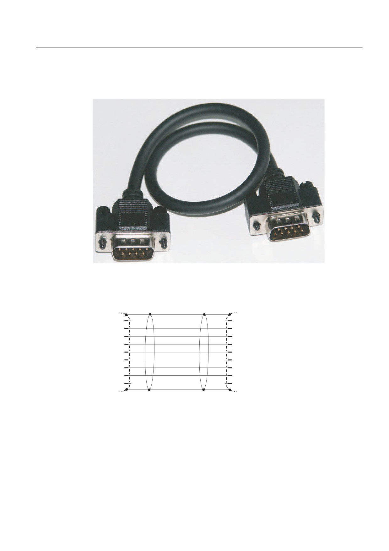
MPI cable
UL cable, AWM 2464, 80°C, 300V, 28 AWG, VW-1
Figure 4-4
MPI cable, 0.8 m with 9-pin sub D connectors
Signal assignment
6KLHOG
1&
1&
0
9
/7*B%
576$6
0 9
1&
1&
3
9
/7*B$
1&
1&
6KLHOG
6XE ' SLQ
6XE ' SLQ
Figure 4-5
MPI cable (0.8 m)
25
Hardware configuration of the TS Adapter II
4.5 USB interface
4.5
USB interface
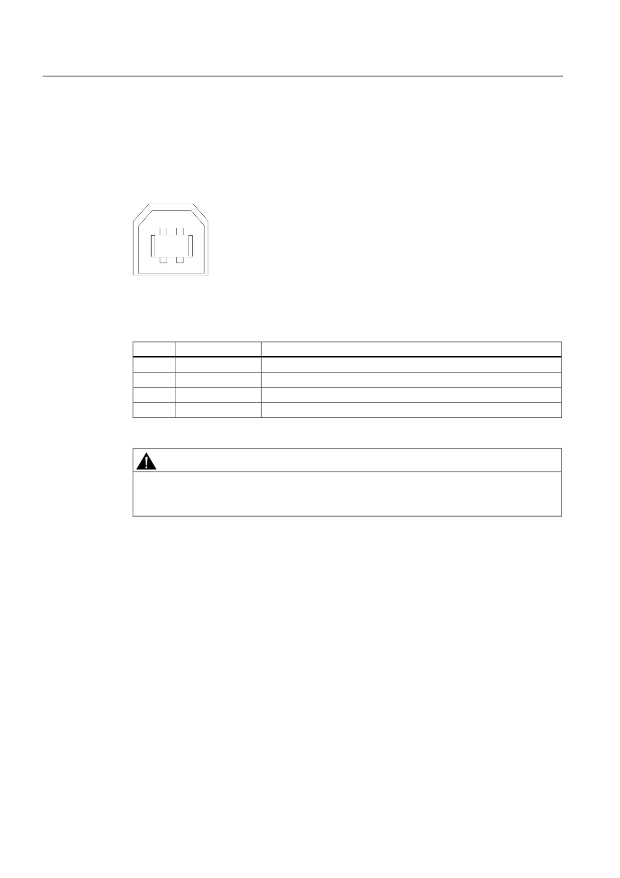
Interface assignment
Top view of the USB socket:
Signal description
Pin no.
Signal
1
+5V
Power supply
2
-Data
- Differential signal
3
+Data
+ Differential signal
4
Ground
Ground
CAUTION
If multiple USB devices are operating on your PC, this can affect the data transmission
times. To achieve optimal performance of communication functions with the automation
system, any unnecessary USB devices should be removed.
26
Hardware configuration of the TS Adapter II
4.6 RS232 interface
4.6
RS232 interface
The TS Adapter II has a COM interface configured as an RS232C interface, which is used
solely for connecting external modems.
Standard modems, ISDN terminal adapters, or GSM radio modems can be connected to and
operated on the COM interface.
Note
The firmware detects the insertion of an external modem and switches automatically from
internal to external modem operation.
Simultaneous internal and external modem operation is not possible.
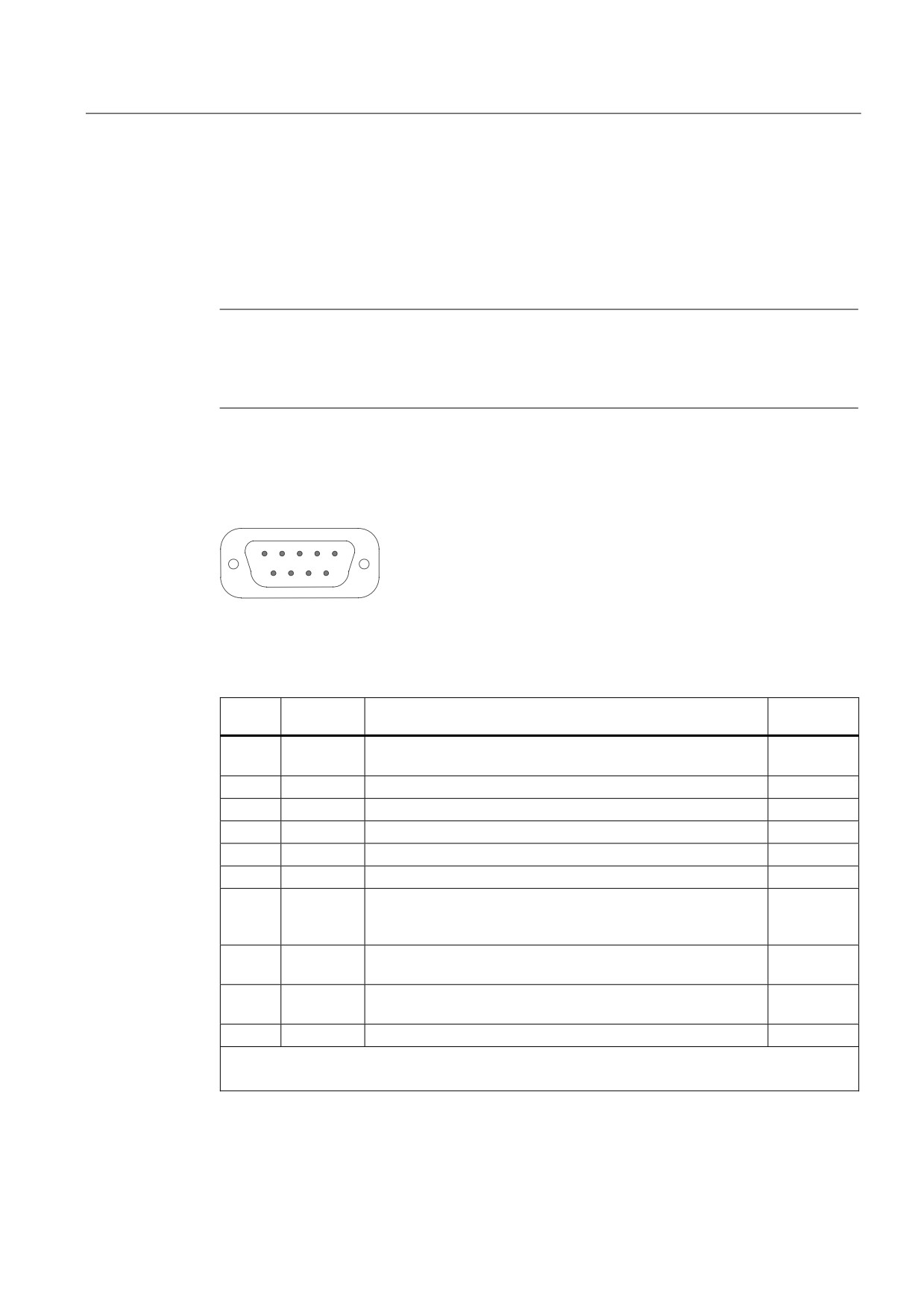
Connector assignment
The RS232 plug connector has the following pinout:
Signal description
Pin. No.
Short
Meaning
Input/
description
output
1
DCD
Data carrier detect - the DCE signals to the DTE the reception
Input
of a carrier or the connection setup
2
RXD
Receive data - from DCE1 to DTE2
Input
3
TXD
Transmit data - from DTE to DCE
Output
4
DTR
Data terminal ready - the DTE signals this to the DCE
Output
5
GND
Internal reference ground
6
DSR
Data set ready - the DCE signals this to the DTE
Input
7
RTS
Request to send - the DTE requests the DCE to transmit data
Output
on the data cable. The DTE waits for the CTS (clear to send)
signal from the DCE
8
CTS
Clear to send - the DCE is able to transmit the data incoming
Input
from the DTE
9
RI
Ring indicator - the DCE signals reception of a call signal to the
Input
DTE
Shield
On connector casing
-
1 DCE = Data communication equipment
2 DTE = Data terminal equipment
27
Hardware configuration of the TS Adapter II
4.7 Power plug for power supply
4.7
Power plug for power supply
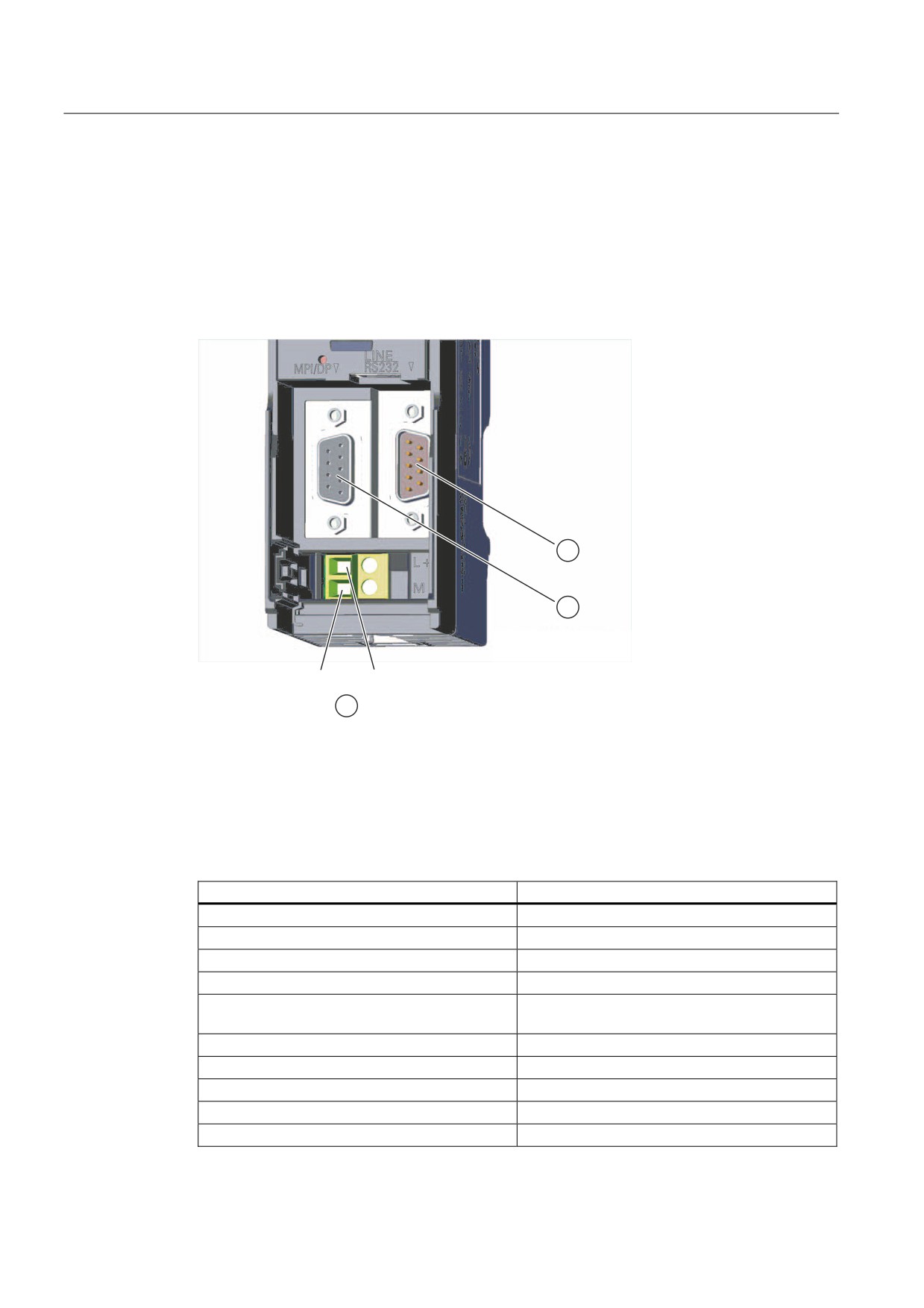
Supply system connection
The 24 V supply voltage can be delivered via the MPI/DP interface cable or the power cord
for the power supply. The 24 V infeed socket is located at the bottom of the module front
panel.
9
9
① RS232 serial interface
② MPI/DP socket
③ Infeed socket for power supply
Connectable cables for 24 V power plug
On TS Adapter II
Solid wires
No
Flexible cables
• Without end sleeve
0.25 mm2 to 2.5 mm2
• With end sleeve
0.25 mm2 to 1.5 mm2
Number of conductors per terminal
1 cable or 2 cables up to 1.5 mm2 (total) in a
common end sleeve
Diameter of the cable insulation
Max. 3.8 mm
Stripped length
11 mm
End sleeves in accordance with DIN 46228
• Without insulating collar
Design A, 10 mm to 12 mm length
• With insulating collar
Form E, up to 12 mm long
28
Hardware configuration of the TS Adapter II
4.7 Power plug for power supply
Note
For information on how to connect the power supply, refer to section "Connecting the
TS Adapter II".
29
Hardware configuration of the TS Adapter II
4.8 Modem interfaces
4.8
Modem interfaces
4.8.1
TS Adapter II-Modem variant
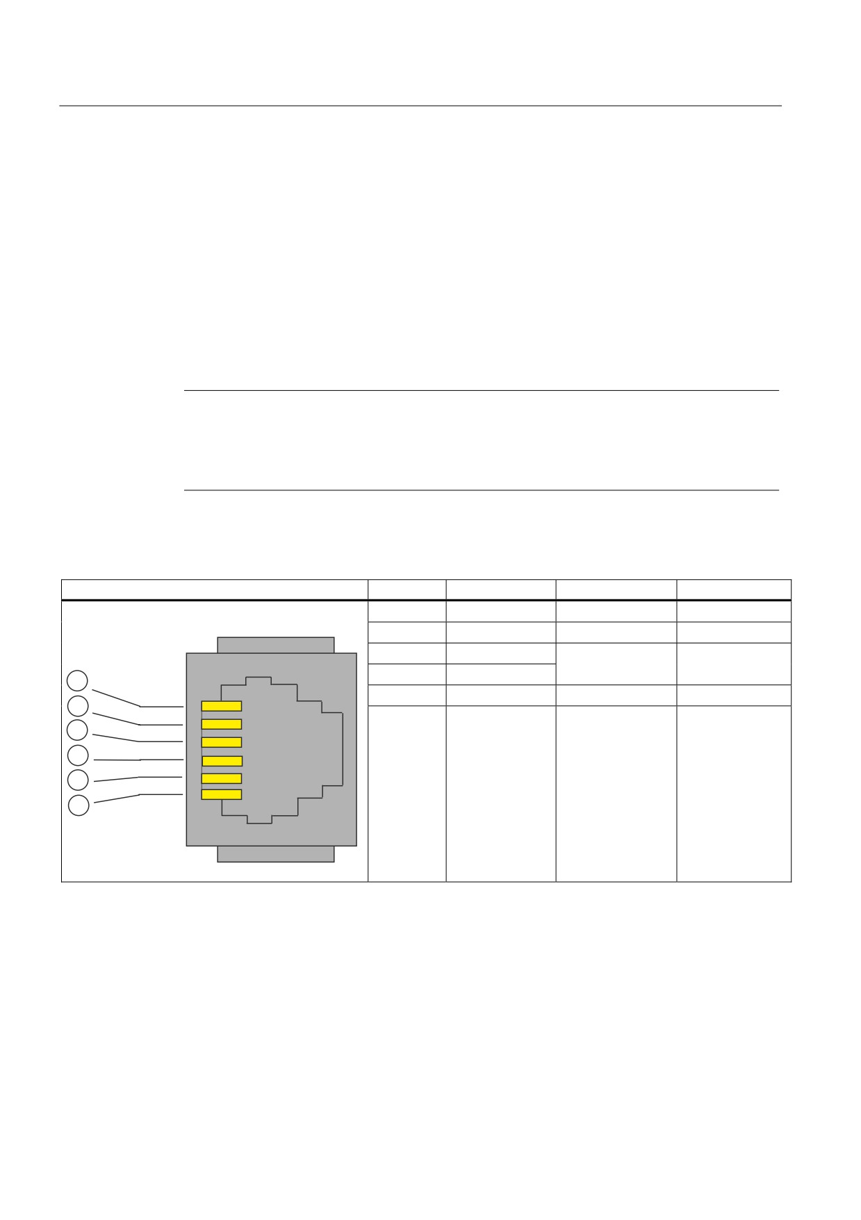
The TS Adapter II-Modem variant has an analog modem interface with a 6-pin RJ12
connector. The supplied analog phone cable is connected to this interface. This allows the
modem to be connected to a phone socket. The length of the cable is 3 m.
Analog phone cable
Note
To use the TS Adapter II-Modem outside Germany, a TAE plug adapter for the country in
question can be applied to the RJ12 connector. For Germany, a TAE6N connector is
supplied. In some countries, phone sockets with RJ12 sockets are already available, in
which case you can use the phone cable without any TAE connector.
Connector assignment and signal description
Illustration
Pin no.
Signal name
Signal direction
Comments
1
2
3
b1
Bidirectional
Incoming wire
pair
4
a1
6
5
5
6
4
3
2
1
30
Hardware configuration of the TS Adapter II
4.8 Modem interfaces
4.8.2
Technical specifications of the analog modem
Modem modules of the SIM family are used on the TS Adapter II. These modules are small,
highly integrated, state-of-the-art data communication units.
Properties / technical specifications
● ITU Transmission Standards:
V.21, V.22, V.22 to, V.23, V.32, V.32 to, V.34, V.34x, K56flex, V.90, V.92
● Error correction and data compression
● Supply voltage 3.3 V
● Serial interface V.24/TTL, 300 kbps to 115 kbps
● a/b interface
● Hayes (AT) command set
● All data formats
● Dial procedures: Dual-tone multiple-frequency (DTMF), pulse dialing
Country list
Explicit telecommunications approvals have been obtained for the following countries:
• Australia 1)
• Iceland
• Poland
• Belgium
• Italy
• Portugal
• Bulgaria
• Canada
• Romania
• Denmark
• Latvia
• Sweden
• Germany
• Lithuania
• Switzerland
• Estonia
• Luxembourg
• Slovakia
• Finland
• Malta
• Slovenia
• France
• New Zealand 1)
• Spain
• Greece
• The Netherlands
• Czech Republic
• Great Britain
• Norway
• Hungary
• Ireland
• Austria
• USA
• Cyprus
1) As of hardware version 03. Extended modem parameterization (initialization) is also
required See product information.
For information on approval in other countries, please contact Technical Support.
Note
The modem in the TS Adapter II modem variant is design for use worldwide. Ensure
compliance with national laws and country-specific requirements when installing and
operating the TS Adapter II modem.
Customer Support has a list of countries in which the TS Adapter II modem cannot be used.
Please request this list in cases of doubt.
31
Hardware configuration of the TS Adapter II
4.8 Modem interfaces
4.8.3
TS Adapter II-ISDN variant
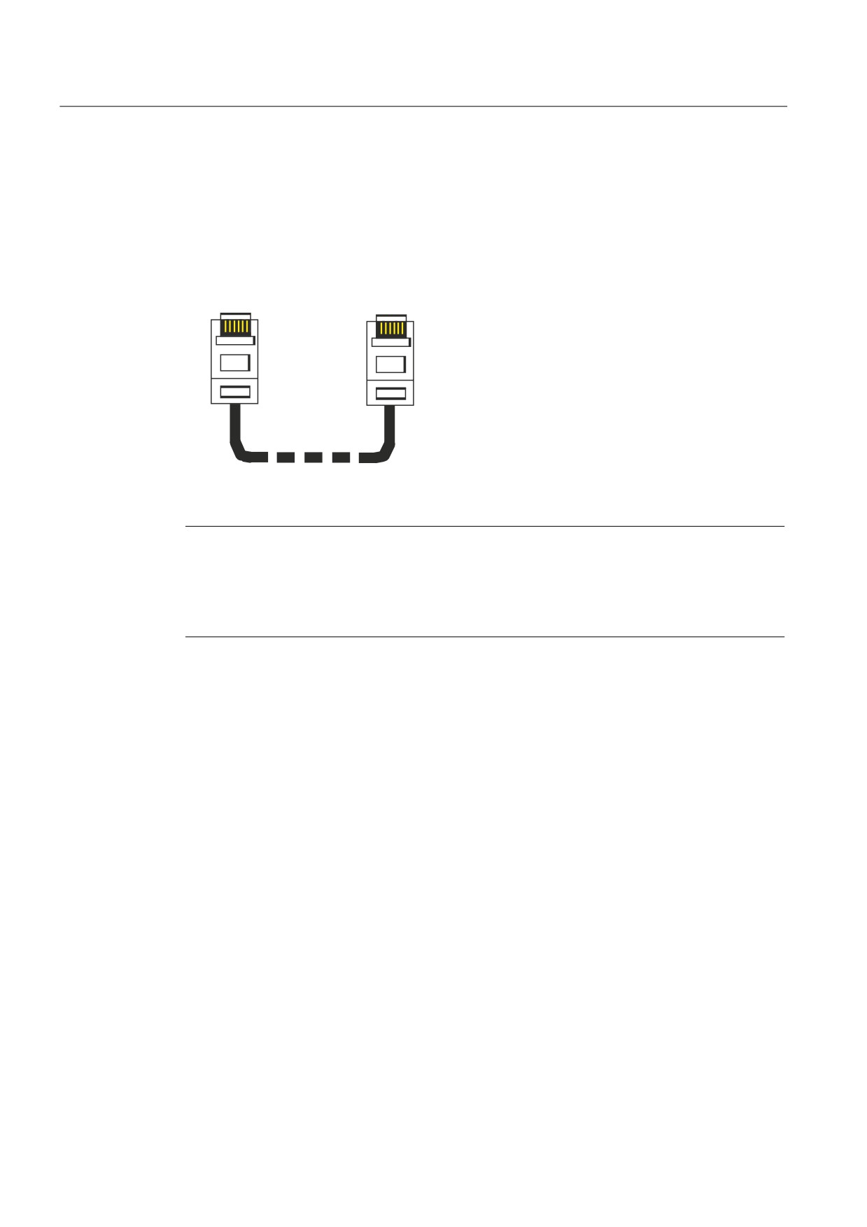
The TS Adapter II-ISDN variant provides an S0 interface at the 8-pin RJ45 socket. Using the
supplied ISDN phone cable, you can connect the TS Adapter II to an ISDN S0 socket. The
length of the cable is 3 m.
ISDN phone cable
5-
5-
Note
When inserting, grasp the cable just below the RJ45 connector. Make sure the RJ45
connector engages audibly.
You can remove the connector as follows:
• Using a screwdriver, press the connector jack to the left and then remove the cable.
32
Hardware configuration of the TS Adapter II
4.8 Modem interfaces
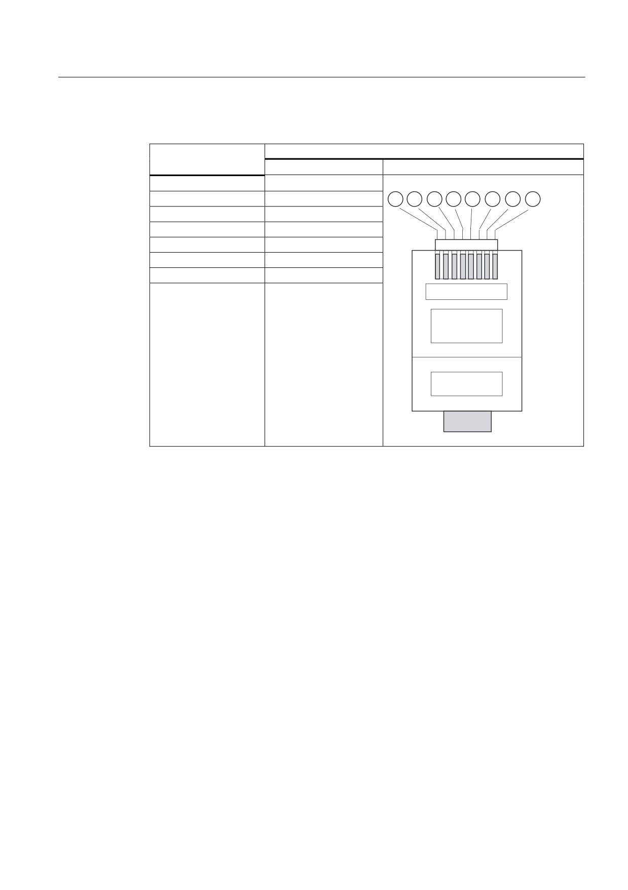
Connector assignment and signal description
RJ-45 Western plug
Signal name
Pin no.
Illustration
-
1
-
2
TX-
3
RX-
4
RX+
5
TX+
6
-
7
-
8
33
Hardware configuration of the TS Adapter II
4.8 Modem interfaces
4.8.4
Technical specifications of the ISDN terminal adapter
The TS Adapter II is equipped with a modular active ISDN terminal adapter, which is
controlled with TTL signal levels via a serial interface.
Properties / technical specifications
● D-channel protocols DSS1 (Euro-ISDN), 1TR6, NI1, 5ESS, DMS100
● Additional protocol-specific parameters
- Multiple subscriber number (MSN)
- Directory number (DN)
- Service profile identifier (SPID)
● Support for the major B-channel protocols:
V.110 (9600 bps, 19200 bps, 38400 bps)
V.120 (64 kbps, 56 kbps)
X.75 (64 kbps)
● Supply voltage 3.3 V
● Serial interface V.24/TTL, 300 kbps to 115 kbps
● AT command interpreter
Country list
Explicit telecommunications approvals have been obtained for the following countries:
• Belgium
• Canada
• Sweden
• Bulgaria
• Latvia
• Switzerland
• Denmark
• Lithuania
• Slovakia
• Germany
• Luxembourg
• Slovenia
• Estonia
• Malta
• Spain
• Finland
• Netherlands
• Czech Republic
• France
• Norway
• Turkey
• Greece
• Austria
• Hungary
• United Kingdom
• Poland
• USA
• Ireland
• Portugal
• Cyprus
• Italy
• Romania
For information on approval in other countries, please contact Technical Support.
Note
Ensure compliance with national laws and country-specific requirements when installing and
operating the TS Adapter II ISDN.
34
Working with the TS Adapter II
5
5.1
Safety notices
Qualified personnel
The device may only be serviced by qualified personnel. Qualified persons are defined as
persons who are authorized to commission, to ground and to tag circuits, equipment, and
systems in accordance with established safety practices and standards.
Correct usage:
WARNING
The device may be used only for the applications described in the catalog and in the
technical description, and only in connection with devices or components from other
manufacturers that have been approved or recommended by Siemens.
This product can only function correctly and safely if it is transported, stored, set up, and
installed correctly, and operated and maintained as recommended.
5.2
Installing the software
Procedure
1. Insert the supplied "SIMATIC TeleService Edition" CD into the CD-ROM drive of your PC.
2. The setup program starts automatically and guides you through the installation.
If the autostart function for your CD-ROM drive is disabled, run the setup program by double-
clicking Setup.exe in the root folder of your "SIMATIC TeleService Edition" CD.
35
Working with the TS Adapter II
5.3 Setting the PG/PC Interface
5.3
Setting the PG/PC Interface
Procedure
During installation of the software you are prompted to set the PG/PC interface.
1. In the "Set PG/PC Interface" dialog, check whether the following interface parameter has
been assigned.
The selection list must contain the entry:
- TS Adapter
If this is not the case,
- click "Select..." to add/remove an interface. The "Install/Remove Interface" dialog box
opens.
- Select the "TS Adapter II" module from the selection list and install the adapter. Click
"Close" to close the dialog box.
2. In the "Set PG/PC Interface" dialog, select the interface parameter assignment that you
want to use in the future for communication (TS Adapter). Click the "Properties" button.
3. The "Properties - TS Adapter" dialog box opens. Open the "Local Connection" tab. Set
"USB" as the direct connection.
4. Click "OK" to close the "Properties - TS Adapter" dialog box.
5. Click "OK" to close the "Set PG/PC Interface" dialog box.
6. If you have changed an access path in these settings, a warning message then appears.
To apply the changes, click "OK".
36
Working with the TS Adapter II
5.4 Connecting the TS Adapter II
5.4
Connecting the TS Adapter II
Connecting to the PC
1. When prompted to do so, insert the supplied USB cable onto a USB interface of your PC.
2. Insert the other end of the USB cable onto the USB interface of the TS Adapter II.
Connecting to the automation system
1. Insert the supplied MPI cable onto the TS Adapter II and tighten the screws.
2. Insert the other end of the MPI cable onto the MPI interface of your CPU and tighten the
screws.
Note
The adapter and the S7/C7 system each represent a node.
1. In networks consisting of two nodes (adapter and S7/C7 system), the adapter is
operated directly at the socket of the S7/C7 system.
2. In networks consisting of more than 2 nodes, the adapter is either connected to the
"PG socket" of a PROFIBUS cable connector (SINEC L2 bus connector) using the
supplied MPI cable or connected directly into the ring using a PROFIBUS cable
connector. In this case, the adapter must additionally be supplied with 24 V.
Connecting to 24 V
Wire the supplied 24 V connector as shown in section "Power cord for power supply" and
insert the connector into the TS Adapter II. The supplied MPI cable or the power cord
supplies the voltage to the TS Adapter II. The power cord must be used to supply the voltage
if the CPU that is connected to the TS Adapter II via the MPI cable cannot supply 24 V.
Note
If 24 V are delivered over the MPI cable and the 24 V power cord, the higher voltage
prevails.
Windows cannot detect the TS Adapter II until it is supplied with voltage. When the adapter
is connected initially, the "Found New Hardware Wizard" appears. Select "Install software
automatically (recommended)", then click "Next". Windows will install the pre-installed
TS Adapter II driver (see also section "Installing the software").
Note
Make sure the 24 V supply cable is protected suitably for its cross-section.
37
Working with the TS Adapter II
5.4 Connecting the TS Adapter II
Connecting to the analog phone socket
1. Insert the supplied analog phone cable onto the TS Adapter II.
2. Plug the other end of the phone cable into your phone socket. Use the TAE plug adapter
if necessary.
Note
You can operate the TS Adapter II-Modem on internal and public analog
telecommunications networks (TNV-3 system).
The insulating voltage between the phone side and the remaining electronics is rated for
250 V AC.
WARNING
Connecting the TS Adapter II-ISDN to an analog phone socket is not permitted and can
lead to life-threatening situations and destruction of the adapter.
Connecting to the ISDN phone socket
1. Fold the supplied ferrite over the phone line close to the TS Adapter II-ISDN.
2. Insert the supplied ISDN phone cable onto the TS Adapter II.
3. Insert the other end of the ISDN phone cable into the ISDN socket on your NTBA or your
ISDN socket.
Connecting to the external modem
Use a modem cable to connect your modem to the RS232 plug connector.
38
Working with the TS Adapter II
5.4 Connecting the TS Adapter II
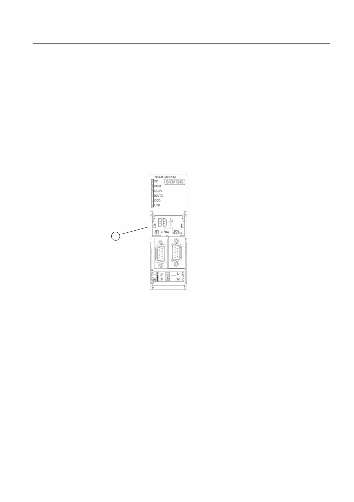
Reset button
The TS Adapter II is equipped with a Reset button that you can use to reset the adapter
parameter assignment to the default parameter assignment. This may be necessary if the
adapter parameters in a remote system have been modified such that the TS Adapter II can
no longer be reached via the phone connection. In this case, the operator of the remote
system must hold the reset button down for approximately 2 seconds.
The DCD-LED of the TS Adapter II flashes three times to acknowledge that a reset operation
was performed remotely by means of the reset button. The TS Adapter II is then reset to the
default parameter assignment.
Figure 5-1
Front view with reset button
① Reset button
39
Working with the TS Adapter II
5.4 Connecting the TS Adapter II
40
TS Adapter II on the MPI/DP/PPI network
6
6.1
General information
A maximum of 32 nodes can be connected to an MPI/DP/PPI network segment. The total
cable length must not exceed 50 m. Multiple network segments can be combined using
RS485 repeaters to form an overall network with a maximum of 127 nodes. The maximum
data transmission rate in the MPI/DP network is 12 Mbps.
The TS Adapter II supports transmission rates up to a maximum of 12 Mbps.
WARNING
Extension cables in addition to the supplied MPI cable are not allowed between the
TS Adapter II and S7/C7 system.
6.2
Use in a stand-alone system
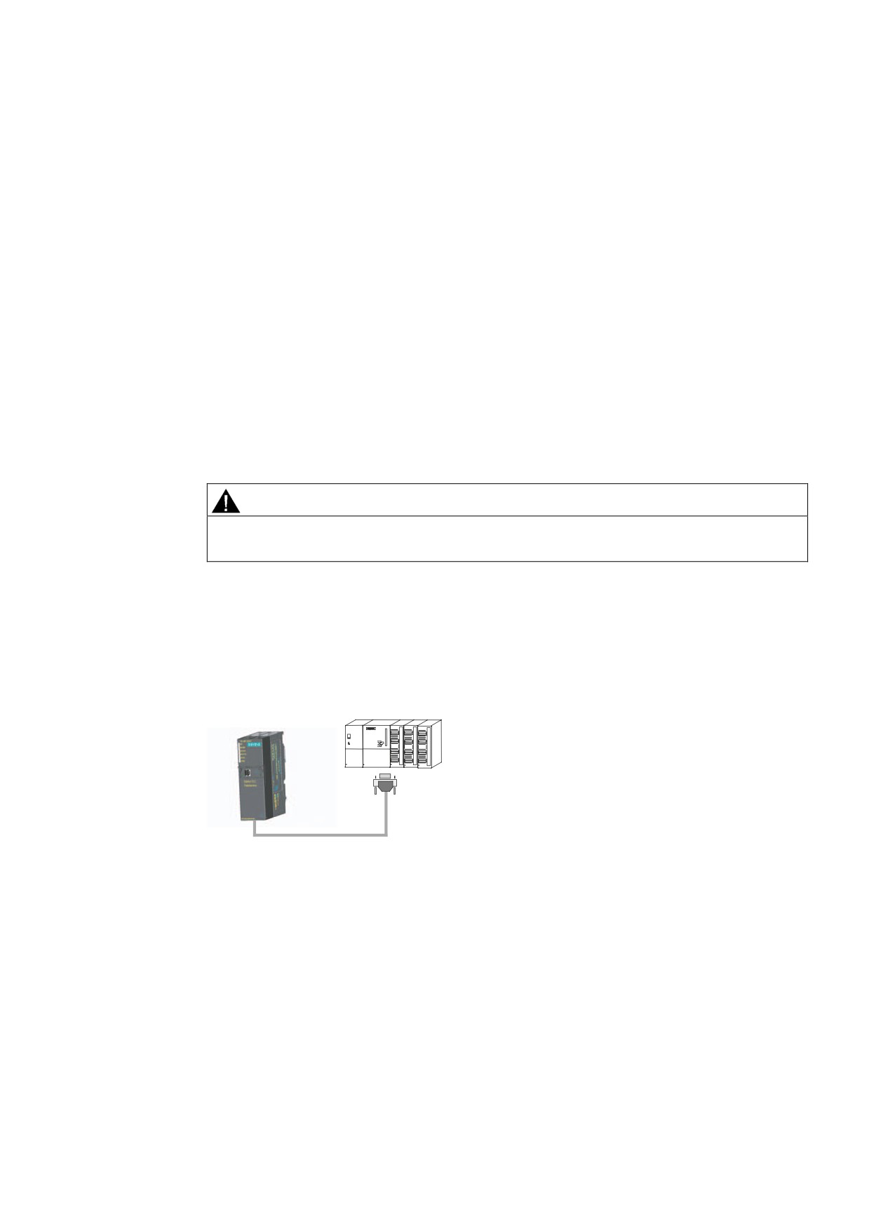
The following figure shows the connection to an individual system (2 nodes). Both nodes are
connected using the supplied MPI cable (0.8 m).
6
Figure 6-1
Connection to a stand-alone system
41
TS Adapter II on the MPI/DP/PPI network
6.3 Use on networked system
6.3
Use on networked system
6.3.1
Connection to networked S7 systems
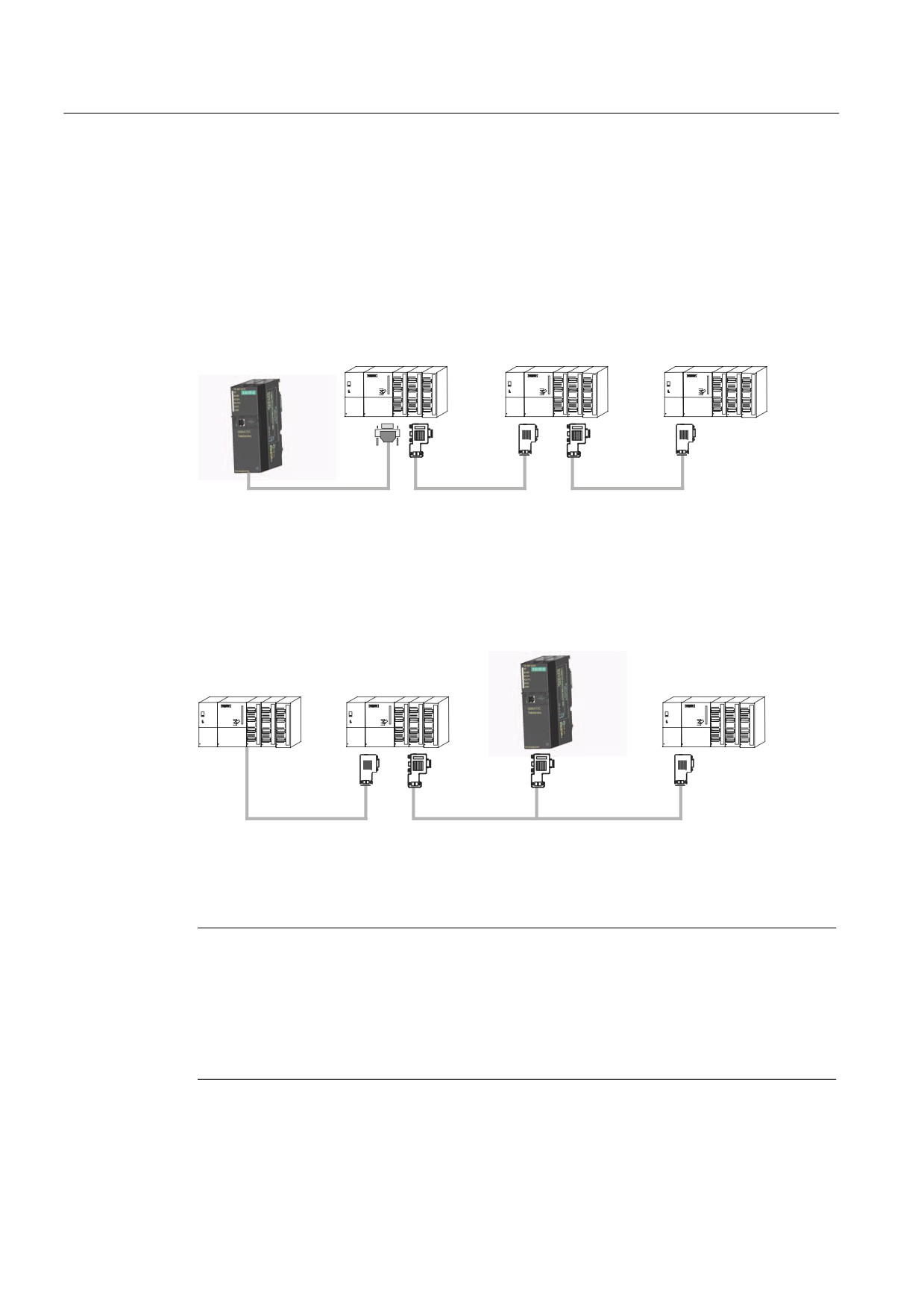
The following figure shows the connection to networked S7 systems (MPI network with 2 or
more nodes). You use the supplied MPI cable to connect the TS Adapter II.
6 [
6 \
6 [
76
$GDSWHU ,,
6XSSOLHG 03, FDEOH
352),%86 FDEOH
352),%86 FDEOH
6.3.2
Connection in the ring
76
$GDSWHU ,,
6 [
6 \
6 ]
H[WHUQDO
9
VXSSO\
352),%86 FDEOH
352),%86 FDEOH
352),%86 FDEOH
You use a PROFIBUS DP connector to connect the TS Adapter II in the ring (not included in
the scope of delivery). In this case, you must supply 24 V to the TS Adapter II.
Note
If you want to install the TS Adapter II together with other S7-300 modules in a rack, you
must take into account the fact that the TS Adapter II has no backplane bus. There must
therefore be no S7-300 modules that communicate with the CPU over the backplane bus
(SM, FM or CP) installed to the right of the TS Adapter II.
If the TS Adapter II is the last module in the ring, the terminating resistors must be activated
on the PROFIBUS DP connector.
42
Firmware update
7
The TS Adapter II firmware can be updated as required, for example, after new features
have been added.
To update the firmware, proceed as follows:
● You will find the latest firmware and the firmware update tool on the Internet at:
● Search for "TS Adapter II" under Product Support.
● Download the self-extracting exe file containing the available firmware and the firmware
update tool to your PC.
● Extract the files to a local drive. Follow the instructions of the firmware update tool to
update the firmware on your TS Adapter II.
● In addition, please read the Readme file in the "Firmware" catalog of the firmware update
tool. This file contains information regarding installation and use of the new firmware.
Note
The firmware current at time of shipping and the firmware update tool is included on your
"SIMATIC TeleService Edition" CD in the "TS Adapter II\Firmware" catalog.
43
Firmware update
44

Error diagnostics
8
To check the functioning of the LEDs, switch the operating voltage of the TS Adapter II off
and back on. All LEDs are switched on when power is restored. After a few seconds, the
LEDs are set according to the current operating state.
Simple malfunctions that you can diagnose and correct in some cases are explained below.
Error/cause
Remedy
SF and BUSF LEDs are lit
• The assigned network parameters of the TS Adapter II are
•
Use TeleService to check and modify the network
incorrect.
parameter assignment of the TS Adapter II.
• MPI cable is not inserted
•
Insert MPI cable
• Automation system is switched off
•
Switch on the automation system
SF LED lit, BUSF LED not lit
• The TS Adapter II cannot communicate with the modem.
•
Check the cabling to the modem and switch on the
modem, if necessary
• The modem replies with an error message
•
Use TeleService to check and modify the modem
parameter assignment of the TS Adapter II.
DC3V LED not lit
• MPI cable is not inserted
•
Insert MPI cable
• Automation system is switched off.
•
Switch on the automation system
• The external power supply is not connected or is switched
•
Connect or switch on external power supply
off
• Hardware error has occurred
•
Inform Customer Support
USB LED not lit
• The USB cable is not inserted
•
Insert the USB cable
• The PC and the USB interface of the TS Adapter II is in
•
Impermissible operating mode
hibernate mode.
• TS Adapter II is not detected by the PC.
•
Check and install the software, if necessary
No LED lit
• MPI cable is not inserted
•
Insert MPI cable
• The 24 V supply is not available when using the MPI/DP
•
Check the cabling
socket.
• Automation system is switched off.
•
Switch on the automation system
• The external power supply is not connected or is switched
•
Connect or switch on external power supply
off
• Hardware fault has occurred.
•
Inform Customer Support
All LEDs flashing continuously
• Hardware fault has occurred.
•
If all the LEDs on the device continue to flash after
reinsertion of the MPI cable or the external voltage
supply, the device is defective and must be replaced.
45
Error diagnostics
46
Appendix
A
A.1 Standards, Approvals, Certificates, Guidelines, Labels, and Declarations
Note
The currently valid approvals are to be found on the product rating plate.
Safety requirements
● The TS Adapter II meets the requirements and criteria of the IEC 61131-2 standard.
● The IT interface is subject to the IEC 60950 standard.
CE mark
Our products conform to the requirements and safety objectives of the EC Directives listed
below. They are compliant with the harmonized European Standards (EN) for programmable
logic controllers as published in the official gazettes of the European Community:
●
2004/108/EC "Electromagnetic Compatibility" (EMC Directive)
●
94/9/EC "Equipment intended for use in potentially explosive atmospheres" (ATEX)
●
1999/5/EC "Radio and telecommunications terminal equipment" (RTTE Directive)
The EC Declarations of Conformity are available to the relevant authorities at:
Siemens Aktiengesellschaft
Industry Sector
I IA AS RD ST Typetest
P.O. Box 1963
D-92209 Amberg
47
Appendix
A.1 Standards, Approvals, Certificates, Guidelines, Labels, and Declarations
EMC directive
SIMATIC products are designed for industrial applications.
Area of application
Requirements
Interference emission
Interference immunity
Industry
EN 61000-6-4: 2007
EN 61000-6-2: 2005
Explosion protection directive
Conforming to EN 60079-15:2005 and EN 60079-0:2006 (Electrical apparatus for potentially
explosive atmospheres; Type of protection "n")
II 3 G Ex nA II T3 ... T6
RTTE Directive
● Security: Telecommunications interface tested in accordance with EN 60950-1
● EMC: see EMC Directive
● Network compatibility:
TS Adapter II-ISDN: TBR3
TS Adapter II-Modem: TBR21
Marking for Australia and New Zealand
Our products comply with the requirements of the AS/NZS CISPR 11 standard (Class A).
cULus approval
Underwriters Laboratories Inc., in accordance with
● UL 508 (Industrial Control Equipment)
● C22.2 No. 142 (IND.CONT.EQ)
48
Appendix
A.1 Standards, Approvals, Certificates, Guidelines, Labels, and Declarations
cULus approval, Hazardous Location
cULus Listed 7RA9 INT. CONT. EQ. FOR HAZ. LOC.
Underwriters Laboratories Inc., to
● UL 508 (Industrial Control Equipment)
+$= /2&
● CSA C22.2 No. 142 (Process Control Equipment)
● UL 1604 (Hazardous Location)
● CSA-213 (Hazardous Location)
APPROVED for Use in
● Cl. 1, Div. 2, GP. A, B, C, D T4A
● Cl. 1, Zone 2, GP. IIC T4
Note
The system installation must be compliant with NEC (National Electric Code)
requirements.
For use in Class I, Division 2 environments, the TS Adapter II must be installed in a
cubicle with minimum IP54 protection to IEC 60529.
Information on use of the TS Adapter II in Zone 2 hazardous areas is contained in the
"Product Information ATEX Zone 2.pdf" file,
This file is located on the product CD in the "_Product_Information" folder.
WARNING
Explosion Hazard - Do not disconnect while circuit is live unless area is known to be
non-hazardous.
Explosion Hazard - Substitution of components may impair suitability for Class I,
Division 2 or Class I, Zone 2.
49
Appendix
A.1 Standards, Approvals, Certificates, Guidelines, Labels, and Declarations
FM approval
Factory Mutual Approval Standard Class Number 3611,
Class I, Division 2, Group A, B, C, D, T4A.
Class I, Zone 2, Group II C, T4.
WARNING
Personal injury and property damage can occur.
In potentially explosive atmospheres there is a risk of injury to persons or damage to
property if you connect or disconnect a live electrical circuit, such as connectors, fuses,
switches, when a TS Adapter II is in operation.
Do not connect or disconnect equipment when a flammable or combustible atmosphere is
present.
For use under FM conditions, the TS Adapter II must be installed in a cubicle with minimum
IP54 protection to IEC 60529.
Safety requirements for installation
The TS Adapter II is "open equipment" in accordance with IEC 61131-2, and an "open type"
in accordance with UL / CSA certification.
The alternative installation methods described below are stipulated in order to ensure safe
operation with respect to mechanical strength, flame resistance, stability and touch
protection:
● Installation in a suitable cabinet
● Installation in a suitable enclosure
● Installation in an appropriately equipped and closed operating area
Observing installation guidelines
The installation guidelines and safety instructions set out in this manual must be observed
during commissioning and operation.
Connecting peripherals
Interference immunity requirements are met when connected to an industrial standard
PC/modem in accordance with EN61000-6-2:2005.
50
Appendix
A.1 Standards, Approvals, Certificates, Guidelines, Labels, and Declarations
Approval regulations
The TS Adapter II modem is designed for connection to the analog public
telecommunications network. In Germany, the device is connected by means of the supplied
standard cable with TAE connector and N-coding.
The TS Adapter II ISDN is designed for connection to the digital public ISDN network. Use
the supplied standard ISDN cable for connection.
EU approval
This equipment has been approved in accordance with Council Decision 98/4827EC for pan-
European single terminal connection to the public switched telephone network. However,
due to differences between the individual PSTNs provided in different countries the approval
does not, of itself, give an unconditional assurance of successful operation on every PSTN
network termination point.
Network compatibility
In accordance with the European Telecommunication Standard Institute (ETSI) Guide
EG 201121 (R&TTE Directive), this product conforms to European standard TBR21/TBR3
and to national requirements. Consequently, this product will function correctly in conjunction
with the telecommunications networks of all the member states of the EU as well as in those
countries which support the TBR21/TBR3 standard.
IC and REN for Canada
This equipment meets the applicable Industry Canada Terminal Equipment Technical
Specifications. This is confirmed by the registration number. The abbreviation, IC, before the
registration number signifies that registration was performed based on a Declaration of
Conformity indicating that Industry Canada technical specifications were met. It does not
imply that Industry Canada approved the equipment.
Registration Number:
TS Adapter II Modem: IC 4030A-022 B3V3
TS Adapter II ISDN: IC 5237A-TSA2 ISDN
The RINGER EQUIVALENCE NUMBER (REN) for the TS Adapter II Modem is 1.0. The
REN assigned to each terminal equipment provides an indication of the maximum number of
terminals allowed to be connected to a telephone interface. The termination on an interface
may consist of any combination of devices subject only to the requirement that the sum of
the Ringer Equivalence Numbers of all the devices does not exceed five (5.0).
51
Appendix
A.2 Customer Information for ACTA
A.2 Customer Information for ACTA
Customer Information for ACTA
This equipment is compliant with Part 68 of the FCC regulations and requirements adopted
by ACTA. The label on the right sideof this equipment also contains the product ID
(US: CO4DT10B022B3V3 for the TS Adapter II-Modem respectively US:EVIDENAN-
TSA2ISDN for the TS Adapter II-ISDN). This ID must be submitted to the telephone
company on request.
The plug and jack used to connect this equipment to the circuit and telephone network at
your site must conform to FCC Part 68 regulations and requirements adopted by ACTA. A
compliant telephone cord and modular plug is supplied with this product. It is designed to be
connected to a compliant modular jack. See the installation instructions for details.
The REN is used to determine the maximum number of devices on an analog telephone line.
If the number of RENs on an analog telephone line is exceeded, the devices may not ring in
response to an incoming call. In most areas the sum of RENs should not exceed five (5.0).
Contact the local telephone company to ascertain the number of devices that may be
connected to a line, as determined by the total RENs. For products approved after July 23,
2001, the REN forms part of the product identifier that has the format for the TS Adapter II-
Modem: US: CO4DT10B022B3V3.
REN is set to NAN and invalid at the TS Adapter II-ISDN
(product ID US: EVIDENAN-TSA2ISDN. The user does not need to calculate the REN, but
may not exceed a maximum number of 8 ISDN terminals on the network termination.
The telephone company will notify you in advance if services are temporarily discontinued as
a result of your TS Adapter II causing disturbances on the telecommunications network. If
advance notice is not deemed practical, the telephone company will notify the customer as
soon as possible. You will be advised of your rights of filing a complaint with the FCC.
The telephone company may modify its services, equipment, operations or procedures,
which could affect operation of your equipment. In this case, the telephone company will
notify you in advance, thus allowing you to adapt your equipment configuration for
uninterrupted service.
If you experience trouble with the TS Adapter II and require repair or warranty information,
please contact
Siemens Johnson City - SIAC -
One Internet Plaza
Johnson City, TN 37604
If the equipment is causing disturbances on the telecommunications network, the telephone
company may ask you to disconnect the equipment until the problem is resolved.
Connections to a party line service are subject to state tariffs. Contact the state public utility
commission, public service commission or corporation commission for information.
If your premises are equipped with an alarm system which is connected to the telephone
line, ensure the installation of the TS Adapter II does not disable your alarm system. If you
have questions about negative effects on your alarm system, contact your telephone
company or a qualified service point.
Note
Disruptions of the alarm functions of alarm equipment may occur not only as a result of faulty
installation, but also in situations where the TS Adapter II is used as intended (dual channel
mode).
52

Appendix
A.3 General technical specifications
A.3 General technical specifications
What are the general technical specifications?
The general technical specifications include:
● The standards and test values to which the TS Adapter II complies.
● The criteria by which the TS Adapter II was tested.
Order number TSA-II ISDN
6ES7 972-0CC35-0XA0
Order number TSA-II Modem
6ES7 972-0CB35-0XA0
Dimensions
Approx. 125 x 110 x 40 mm
Weight
Approx. 250 g
Interfaces
To SIMATIC S7 / C7
RS 485 (up to max.12 Mbps)
To PC
USB 1.1 (12 Mbps)
To external modem
RS 232 (up to max. 115 kbps)
To analog phone network
RJ 12
To ISDN phone network
RJ 45
Supply voltage, external
24 V DC (SELV) (20.4 V … 28.8 V DC)
or via MPI interface
Current consumption (TSA-II ISDN)
40 mA (typical) / 120 mA (maximum)
Current consumption (TSA-II Modem)
44 mA (typical) / 120 mA (maximum)
Inrush current
Imax 700 mA; 8 µs
53
Appendix
A.3 General technical specifications
Horizontal and vertical installation
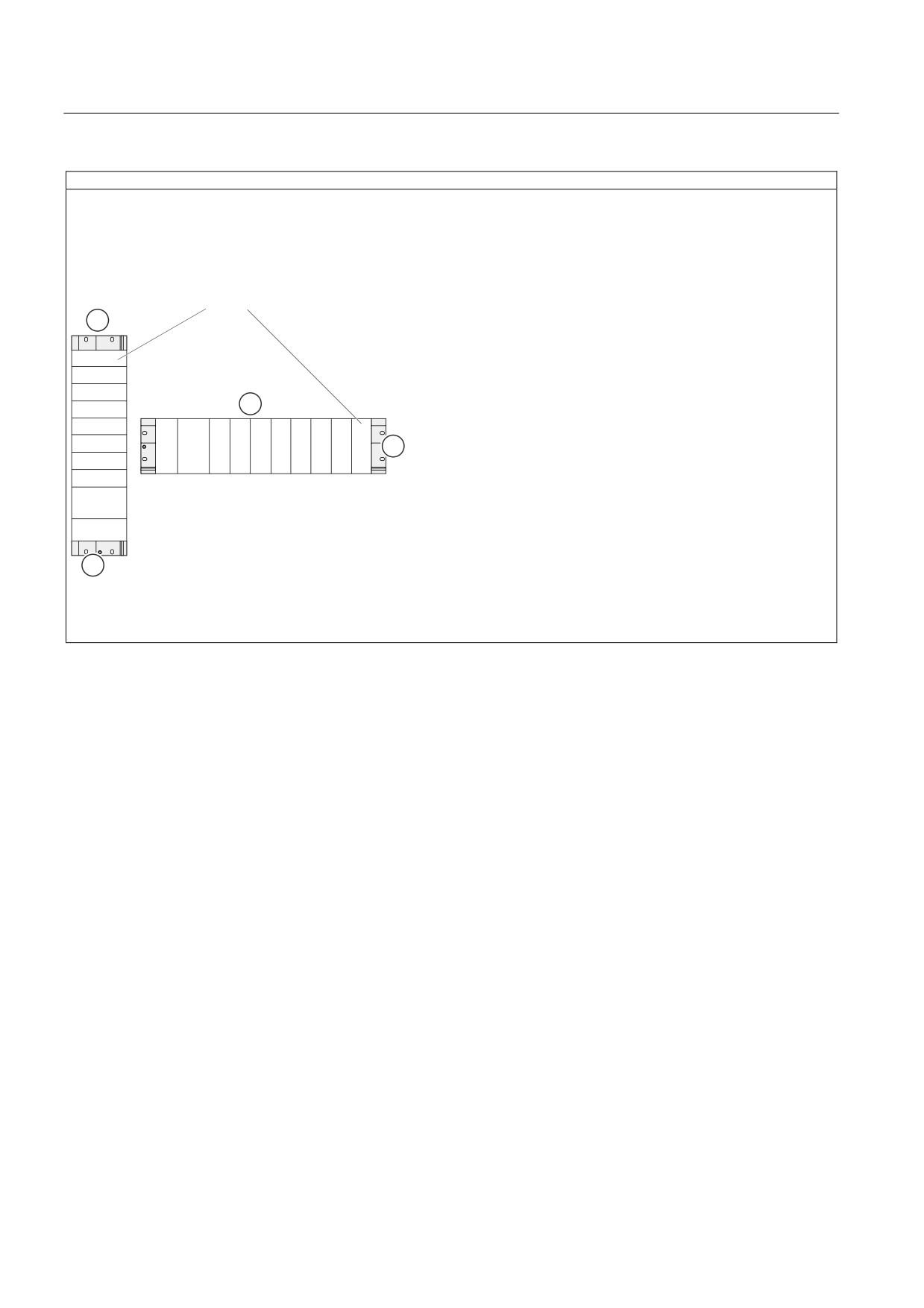
Comply with the general installation guidelines for SIMATIC. Cabinet installation is stipulated. You can install the
TS Adapter II vertically or horizontally. The following ambient air temperatures are permitted:
Vertical installation: 0 to 40 °C
Horizontal installation: 0 to 60 °C
Always install the TS Adapter II at the top or on the right.
76
$GDSWHU
;;
;;
;;
;;
;;
;;
36
&38
;;
;;
;;
;;
;;
;;
;;
;;
;;
;;
&38
36
① the vertical installation of an S7-300
② the horizontal installation of an S7-300
③ the mounting rail
54
Appendix
A.3 General technical specifications
A.3.1
Electromagnetic compatibility
Definition of "EMC"
Electromagnetic compatibility (EMC) is the capacity of an electrical installation to function
satisfactorily in its electromagnetic environment without affecting that environment.
WARNING
Personal injury and damage to property may occur.
Any installation of expansion units which are not approved for TS Adapter II may violate
requirements and standards relating to safety and electromagnetic compatibility.
Only use expansion units that are approved for the system.
Pulse-shaped Interference
The table below shows the electromagnetic compatibility of the TS Adapter II in relation to
pulsed interference. This requires that the electrical installation to comply with relevant
specifications and standards.
Table A-1
Pulse-shaped Interference
Pulse-shaped interference
Test voltage
Degree of
severity
Electrostatic discharge according to IEC 61000-4-2
Air discharge: ±8 kV
3
Contact discharge: ±6 kV
Bursts (fast transient interference in accordance with
2 kV (power supply cable)
3
IEC 61000-4-4)
2 kV (Signal cable > 30 m)
1 kV (Signal cable < 30 m)
Powerful single pulse (surge) according to IEC 61000-4-5
3
• Asymmetrical coupling
2 kV (power supply line) DC with protective
elements 1
1 kV (signal/data line only >30 m), with
protective elements as required
• Symmetrical coupling
1 kV (power supply line) DC with protective
elements 1)
1 e.g. surge arresters from Dehn
Type: BD VT AD24
Order no. 918402
55
Appendix
A.3 General technical specifications
Sinusoidal Interference
The table below shows the electromagnetic compatibility of the TS Adapter II in relation to
sinusoidal interference.
Table A-2
Sinusoidal Interference
Sinusoidal interference
Test values
Degree of
severity
HF irradiation (electromagnetic fields) according to
10 V/m with 80% amplitude modulation of 1 kHz
3
IEC 61000-4-3
in the range from 80 MHz to 1000 MHz and 1.4
GHz to 2 GHz
1 V/m with 80% amplitude modulation of 1 kHz
over the range from 2 GHz to 2.7 GHz
RF interference current on supply, cables and
Test voltage 10 V, with 80% amplitude modulation
3
cable shielding conforming to IEC 61000-4-6
of 1 kHz in the 10 MHz to 80 MHz range
Emission of Radio Interferences
Interference emission of electromagnetic fields according to EN 55011: Limit value class A,
Group 1.
Additional measures
If you want to operate the TS Adapter II in an office environment, you must ensure
compliance with limit class B to EN 55022.
Take suitable measures for increasing resistance to high external interference levels as
required.
56

Appendix
A.3 General technical specifications
A.3.2
Shipping and storage conditions
Shipping and storage of modules
The TS Adapter II surpasses the requirements of IEC 61131-2 with respect to transportation
and storage conditions. The following specifications apply to TS Adapter II units that are
transported and stored in their original packaging.
Climatic conditions correspond to IEC 60721-3-3, Class 3K7 for storage and IEC 60721-3-2,
Class 2K4 for transportation.
Mechanical conditions are compliant with IEC 60721-3-2, Class 2M2.
Table A-3
Shipping and storage conditions for modules
Permissible range
Temperature
-40 °C to +70 °C
Atmospheric pressure
1080 to 660 hPa (corresponds to an altitude of -1000 to
3500 m)
Relative humidity (at +25° C)
5% to 95%, no condensation
Sinusoidal vibrations in accordance
5 - 9 Hz: 3.5 mm
with IEC 60068-2-6
9 - 500 Hz: 9.8 m/s2
Shock in accordance with IEC 60068-2-
250 m/s2, 6 ms, 1000 shocks
29
A.3.3
Mechanical and climatic environmental conditions for operation of the
Operating conditions
The TS Adapter II is designed for weather-protected, stationary use. The TS Adapter II
complies with the operating conditions defined in DIN IEC 60721-3-3:
● Class 3M3 (mechanical requirements)
● Class 3K3 (climatic environmental conditions)
Use with additional measures
The TS Adapter II must not be used under the conditions outlined below without taking
additional measures:
● At locations with a high degree of ionizing radiation
● In locations subject to harsh operating conditions, such as dust, aggressive fumes or
gases, severe electrical or magnetic fields
● In installations requiring special monitoring, such as elevators and electrical systems in
high risk areas
An additional measure can be installation of the TS Adapter II in a cabinet or in an enclosure,
for instance.
57

Appendix
A.3 General technical specifications
Mechanical environmental conditions
The table below sets out the mechanical environmental conditions for the TS Adapter II in
the form of sinusoidal vibrations.
Table A-4
Mechanical environmental conditions
Frequency range in Hz
Test values
10 ≤ f < 58
0.075 mm amplitude
58 ≤ f < 500
9.81 m/s2 constant acceleration
Reduction of vibrations
If the TS Adapter II is subject to greater shocks or vibrations, you must take suitable
measures in order to reduce the acceleration or amplitude.
We recommend the installation of the TS Adapter II on damping materials (for example,
rubber-metal vibration dampers).
Testing for Mechanical Environmental Conditions
The following table provides information about the type and scope of testing for mechanical
environmental conditions.
Table A-5
Test for mechanical environmental conditions
Test
Test Standard
Remarks
Vibrations
Vibration test in
Type of vibration: frequency sweeps with a rate of
accordance with IEC
change of 1 octave/minute.
60068-2-6 (sinusoidal)
10 Hz ≤ f < 58 Hz, constant amplitude of 0.075 mm
58 Hz ≤ f < 500 Hz, constant acceleration of
9.81 m/s2
Duration of vibration: 10 frequency cycles per axis
in each of the 3 perpendicular axes
Shock
Shock impact test to IEC
Type of shock: half-sine
60068-2-29
Type of shock: 150 m/s2 peak value, 11 ms period
Direction of shock: 100 shocks on each of the 3
perpendicular axes
58

Appendix
A.3 General technical specifications
Climatic environmental conditions
The TS Adaptor II may be used under the following climatic environmental conditions:
Table A-6
Climatic environmental conditions
Environmental conditions
Permissible range
Comments
Temperature
0 to +60 °C
Horizontal installation
0 to +40 °C
Vertical installation
Temperature change
Max. 10 °C/h
Relative humidity
Max. 95% at +25° C
No condensation,
corresponds to relative
humidity degree 2 to
IEC 61131-2
Atmospheric pressure
1080 to 795 hPa (corresponds to an
-
elevation of
-1000 to 2000 m)
Contaminant concentration
SO2: < 0.5 ppm;
Check: 10 ppm; 4 days
RH < 60%, no condensation
Check: 1 ppm; 4 days
H2S: < 0.1 ppm;
RH < 60%, no condensation
A.3.4
Specification of Insulation Testing, Protection Class and Degree of Protection /
Test Voltage
Test voltage
The TS Adapter II-MODEM can also be operated in TNV-3 systems. The insulating voltage
between the phone end and the processing end is rated at 250 V AC. In routine testing of the
TS Adapter II-MODEM, the reinforced insulation between the phone end and the rest is
tested with 2200 V DC for 1 second in accordance with EN 60950-1, March 2003.
Protection class
Protection class I in accordance with EN 61140 (VDE 0140-1), i.e., the mounting rail or DIN
rail on which the TS Adapter II is installed must be grounded.
Protection against the ingress of foreign matter and water
Degree of protection IP 20 in accordance with IEC 60529, i.e., protection against contact
with standard probes.
There is no protection against the ingress of water.
59