CDM520A & CDM520K road roller - manual
Preface
Thank you for selecting our products.
This manual is prepared for operator, serviceman and technician in order to provide necessary information about the performance, structure, operation, maintenance and control of CDM520A & CDM520K road roller.
Owing to the rapid development of technology and our constant improvement of product, the information contained in this manual may be changed without notice.
For improving our product and service, customers are kindly requested to give us comments and suggestions after reading this manual.
This is the first edition.
China Infrastructure Machinery Holdings Limited
May, 2007
China Infrastructure Machinery Holdings Limited
Address:26 Minyi Road, Songjiang Industril, Shanghai, China
Tel:+86-21-57644948
Fax:+86-21-57644049
Postal code:201612
http://www.chinalonggong.com
Table of contents
Chapter 5 Operation Mechanism and instrument
1. Preparation before starting the engine
6. When to be towed, lifted or transported
1. Points to be checked at maintenance
3. Precautions for fuel system
4. Precautions for hydraulic system
5. Items for periodic maintenance
Chapter 1 Summary
Read the manual carefully before operating the machine as it provides helpful information about the features, operation and maintenance of the roller. Correct operation and maintenance can make the machine serve you better.
CDM520A&CDM520K are multi-purpose road rollers with heavy weight and mechanical drive. It is with hydraulic vibration, power shift, power steering, mechanical drive, articulated hydraulic steering, fuel refilling system, maintenance-free battery and optional A/C, and featured in strong vibration force and single frequency/two amplitude. Various materials can be compacted. Hydraulic vibration system is a closed-type hydraulic system composed of variable plunger pump and ration plunger motor. The powertrain system consists of a 3-speed transmission and a rear axle that assure good maneuverability and gradeability. Hydraulic steering system provides flexible operation.
The articulated beam frames are easily accessible for maintenance. Vibration-proof and sound insulation cab provides comfortable condition for operator.
The specifications are of this manual are collected for reference and subject to change without notice, and are not to be used as criteria of acceptance.
Refer to the engine user’s manual for operation and maintenance of engine.
Refer to the transmission user’s manual for operation and maintenance of transmission.
Refer to the air conditioner user’s manual for operation and maintenance of air conditioner.
For making the best use of the CDM520A&CDM520K, follow the instruction in this manual.
Overall Dimensions
 |
 |
Figure 01 Overall Dimensions (for CDM520A)
|
|
Figure 01 Overall Dimensions (for CDM520K)
Chapter 2 Specifications
|
Specifications |
Value |
|
Operating weight(kg) |
20000 |
|
Weight distributed on drum(kg) |
9500 |
|
Weight distributed on rear tires(kg) |
10500 |
|
Static Linear Load of drum (N/cm) |
435 |
|
Excitation force (KN) |
351/200 |
|
Vibration frequency(Hz) |
28 |
|
Nominal amplitude(mm) |
1.9/1.0 |
|
Min. turning radius(mm) |
6300 |
|
Max. gradeability |
30% |
|
Minimum clearance from ground(mm) |
400 |
|
Max. turning angle(º) |
35±1 |
|
Wheelbase (mm) |
3020 |
|
Drum diameter(mm) |
1520 |
|
Drum width(mm) |
2180 |
|
Travel speed (km/h) |
GearⅠ 2.6 |
|
GearⅡ 5.3 |
|
|
GearⅢ 8.6 |
|
|
Diesel engine |
|
|
Model |
D6114ZG2B |
|
Rated power (KW) |
128 |
|
Rated RPM |
2000 |
|
Cranking voltage(V) |
24 |
|
Transmission |
|
|
Pressure(MPa) |
1.3-1.6 |
|
Pump displacement(ml/r) |
25 |
|
Filtration precision(μm) |
30 |
|
Overall dimensions(mm) (Length×Width×Height) |
6145×2440×3210 |
|
6145×2440×3400 (with air conditioner) |
Chapter 3 Safety Precaution
1. General rules
1.1 Only the trained and qualified operator can operate the machine.
1.2 Get full knowledge of structure, performance, system and operation of the machine before operating.
1.3 This machine is suitable for compacting the base and subbase of road. Do not vibrate on high density material such as cement or asphalt.
1.4 Never stand at the turning circle when the engine is running.
2. Before starting
2.1 Check each part according to the instruction. Make sure that the bolts on articulated parts and drum are tightened. Make sure the oil level in transmission, hydraulic tank, clutch oil cup, brake oil cup and drum are in specified range.
2.2 Make sure that all gauges, steering wheel, brakes, lamps and horns are in good condition and reliable.
2.3 Make sure that the speed selector is in neutral position before starting the engine.
2.4 Make sure that no person or obstacle is under or near the machine.
3. Starting
3.1 Operator should not leave the machine when the engine is running.
3.2 Make sure there is no person or obstacle on the road before attempting to travel in reverse direction.
3.3 Travel straightly on slope. Select gear I when approaching a slope.
3.4 Never stop the engine when traveling on slope. Otherwise, steering failure may be caused.
3.5 Apply the service brake before changing speed or direction on slope. Never put speed selector in neutral position when traveling downhill.
3.6 Never use the roller to transport passenger.
3.7 Do not climb on the roller when it is traveling.
3.8 Pay attention to abnormal noise and smoke. Stop and inspect the machine when any problem occurs.
3.9 The maximum speed can be selected only on straight, solid and smooth road. The maximum travel distance should not exceed 30 kilometers.
4. Parking
4.1 Put the speed selector in neutral position, stop the engine and apply the parking brake before leaving roller.
4.2 If the roller has to be parked on slope, make the longitudinal axis of roller be square to the road side and put wedges under the drum and wheels.
5. Maintenance
5.1 Turn off the master power switch before maintenance.
5.2 Keep the roller level and stable during maintenance.
5.3 Support the articulated frame when doing service on the machine.
5.4 Flame and/or fire are strictly prohibited when refilling fuel/oil.
5.5 Check if the pressure in hydraulic system is lower than normal. When repairing the hydraulic system, stop the engine and disassemble any hydraulic tube/hose.
6. Warning
6.1 Depress the throttle pedal to its maximum limit (engine runs at 2000rpm) before starting vibration.
6.2 Never vibrate on high-density material. High amplitude vibration is prohibited when the density is higher than 90%. Vibration must not be performed when the roller is not moving.
6.3 The roller is used for compacting the base and subbase but not for compacting surface.
6.4 Only when the vibration is fully stopped, can the switching between high and low amplitude be done.
6.5 When welding is to be done on roller, turn off the master power switch, and disconnect the two joints connecting transmission.
Chapter 4 Main Structure
1. General description
Road roller is widely used in construction of airports, mines, road and so on.
The vibration frequency of CDM520A&CDM520K is 28Hz. Two amplitudes are available. The roller is especially suitable for compacting the road base and landfill.
The roller is composed of articulated frames, drum, wheels, powertrain system, rear axle, hydraulic vibrator, hydraulic steering system, operation mechanism, electrical system, etc.
Articulated frames provide easy access for maintenance.
The drum is mounted to the front frame. It is of one frequency and two amplitudes. Select suitable amplitude according to the material to be compacted. There are rubber absorbers between drum and frame in order to prevent the vibration being transmitted to the frame.
The tires on the drive wheels locating at two sides of the rear frame are low-pressure air-inflated. They absorb the vibration on ground. The drive force is transmitted from rear axle to the wheels.
The roller is powered by D6114ZG2B diesel engine which is mounted on the rear frame. There is shock absorber between engine and rear frame so that the vibration of engine will not be transmitted to the frame. The engine supplies power to both transmission and hydraulic pump.
The powertrain system is located at the middle of the rear frame. It consists of three-gear transmission and rear axle which make the roller to travel at three speeds in both forward and backward directions and at different speed of two wheels when turning.
The cab is mounted at the front end of rear frame. Shock absorber is mounted between seat and cab so that the vibration will not be transmitted to the operator.
The hydraulic system is equipped with pressure monitor for measuring and adjusting the system pressure. Hydraulic steering system provides flexible operation.
Lighting is available so that the roller can work in night or dark place. Fault alarm will warn the operator troubleshooting is needed.
2. Powertrain system
Refer to Figure 02 for powertrain system. The power from engine is outputted via the flywheel and the transfer box.
The power from engine (1) is transmitted to the transmission (5) via clutch (3) (refer to the transmission user’s manual) so that the roller can get different travel speeds in forward and reverse directions. The power from transmission (5) is transmitted to rear axle (4) which turns the wheels (6) so that the roller can move.
Engine (1) directly rotates the duplex gear pump (2) for hydraulic steering and vibration.
3. Main clutch
The main clutch is a φ380 clutch. It is composed of case, driven disc assembly, pressure disc assembly, spring, etc. It is between engine and transmission. Its function is:
1) To transfer the power from engine;
2) To eliminate the shock between each drive part when the powertrain system is suffered from shock during working.
 Refer
to Figure 03. The pressure disc is connected with the flywheel
housing of engine. The driven disc is pressed on the surface of
flywheel by the spring and rotates with the flywheel. The power is
transmitted to the input shaft via spline of the driven disc, and
then to the transmission.
Refer
to Figure 03. The pressure disc is connected with the flywheel
housing of engine. The driven disc is pressed on the surface of
flywheel by the spring and rotates with the flywheel. The power is
transmitted to the input shaft via spline of the driven disc, and
then to the transmission.
Figure 02 Powertrain System
1. Engine 2. Duplex gear pump 3. Clutch 4. Gear axle
5. Rear axle 6. Wheel 7. Transmission

Figure 03 Main Clutch
1. Driven disc assembly 2. Pressure disc assembly 3. Isolation bearing
To disengage the clutch, depress the clutch pedal to make the fork shaft rotate to push the isolation bearing, the isolation bearing presses the linkage in the pressure disc to overcome the spring force so that the driven disc is separated from the surface of flywheel and the engine runs idly.
4. Drum
Figure 04 Drum
1. End cover 2. Shock absorber 3. Spline sleeve 4. Bearing seat
5. Eccentric block 6. Drum body 7. Drive shaft 8. Inner bearing seat
9. Outer bearing seat 10. Abutment for drum
The drum does compacting with its static weight and vibration force. Refer to Figure 04 for its structure.
Two eccentric blocks are supported on the bearing seats (8) and (9) with two roller bearings. The bearing seats and drum body (6) are fixed together. Two eccentric blocks are connected with drive shaft (7). Bearing seat (9) is supported on bearing seat (4) that is connected with absorber (2). The abutment (10) is connected with absorber and front frame. The two ends of the spline sleeve (3) are connected with the eccentric block and motor. The motor rotates the eccentric block to generate centrifugal force. The motor can run in both directions, so can the eccentric block. When the rotational direction of the motor is changed, the eccentric distance of the eccentric block will be changed and the other amplitude can be obtained.
5. Wheels and rear axle
Two wheels (2) with inflated tires are at two sides of rear frame. Refer to Figure 05 for its structure.
 |
The wheels are mounted on the hub (1) on rear axle. The axle is fixed on rear frame. The rim is connected to the hub (1) with bolts.
Figure 5 Wheels and rear axle
1. Hub 2. Tire 3. Axle shaft 4. Master reducer 5. Input shaft
The power from transmission is transferred to the input shaft (5) of rear axle via drive shaft, then to the wheel reducer via the master reducer and axle shafts, so the roller can move.
6. Brake
There are parking brake and service brake in the machine. Refer to the pneumatic system for the service brake.
The parking brake is drum brake (see Figure 06). It is mounted on the output shaft of transmission. Its control lever is at the right side of driver’s seat. It is for parking the roller securely.
The structure of the parking brake is as shown in Figure 06.

Figure 06 Parking brake
1. Brake wheel 2. Brake disc 3. Lever 4. Flexible shaft 5. Control lever
The brake wheel (1) is mounted on the front output shaft of transmission and turns with the shaft. The brake disc is fixed on the case of brake drum. When applying the brake, pull the lever (5) so that the flexible shaft draws the lever (3), and the brake disc expand to rub the wheel and stop the turning of wheel. At the same time, the ratchet on the lever (5) is engaged to the toothed plate by the spring force so as to keep the roller in place.
7. Pneumatic system
Refer to Figure 07 for the pneumatic system. Air compressor (1) supplies the compressed air to the air tank (7) via the pressure-setting valve (2). The pressure is preset to about 800Kpa in the tank by manufacturer before delivery. The compressed air in the air tank is to be supplied to the clutch booster system and the service brake system.
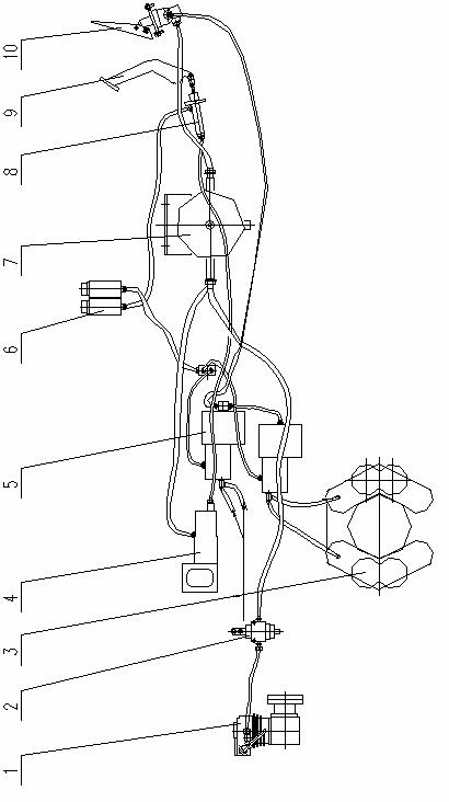
Figure 07 Pneumatic system
1. Air compressor 2. Pressure setting valve 3.Brake caliper 4. Clutch booster cylinder
5. Brake booster cylinder 6. Oil cup 7. Air tank 8. Main cylinder
9. Clutch pedal 10. Air brake valve
7.1. Clutch booster system
The clutch booster system contains both oil and air. When the clutch pedal (9) is depressed, the main cylinder (8) is actuated. The main cylinder (8) delivers the pressure to the booster cylinder (4) via oil pipe. At the same time when the brake fluid pushes the piston, the air valve is opened and the compressed air gets into the booster cylinder (4) to realize the air boosting. If there is not compressed air, when the clutch pedal is depressed, the clutch can be disengaged, but not so easily.
7.2 Service brake system
The compressed air from air tank is delivered to the air brake valve (10), then to the brake booster cylinder(5). When the air brake valve(10) is depressed, the compressed air bursts open the control valve and gets into the brake booster cylinder (5) so as to push the cylinder piston. The piston rod in the cylinder pushes the front cylinder and the oil in the front cylinder is pressed into brake caliper (3) on the rear axle. Two sets of pistons in caliper(3) are pushed out to press the disc for braking.
7.3. Precautions for adjustment
7.3.1. Air tank
1) Open the drain plug to bleed the air after the roller finishes daily work. Wipe off the dust and moisture.
2) There are many connectors around the air tank. Frequently check for leakage, soap solution is available if necessary.
7.3.2. Air bleeding (after stopping the engine)
Air must be bled whenever it gets into the oil line by pipe breakage or demounting. Two persons are needed when bleeding the air. One of them fills brake fluid into the oil cup while reiteratively depressing the pedal to fill the fluid into oil line. The other bleeds the air and follows the following steps after starting the engine to make the air compressor work and stopping the engine when the air pressure reaches 600Kpa:
1) Bleed the air in the clutch booster system: reiteratively depress the pedal (9) to fill the oil into the oil line and fill oil into the oil cup (6). Open the air bleed plug (4) and depress the pedal to bleed the air. Then tighten the air bleed plug. Repeat the above steps until no air bulb is found.
2) Bleed the air in the brake system: depress the air brake valve pedal to get the air line through, and fill the brake fluid for times into the oil cup (6) that is connected to the brake booster cylinder (5), gently unscrew the air bleed plug on the brake caliper, and pump the pedal. Tighten the plug when oil flows out. Repeat the above steps until no air bulb is found.
8. Hydraulic system
Refer to Figure 08 for hydraulic system. The hydraulic system includes hydraulic vibration, hydraulic steering and hydraulic speed-control.
The hydraulic vibration system is composed of variable piston pump and constant piston motor. The hydraulic pump and hydraulic motor compose a closed loop. The direction change for variable pump is realized via electronic control. A rinse valve is in the constant motor to control the oil quality and system temperature. There is a supplementary pump in the piston pump for compensating the loss of leakage (e.g. the leakage at pump, motor, etc).
The rotational direction of hydraulic motor is controlled by the flow direction of oil from hydraulic pump. The motor is connected to the shaft of the eccentric block which is in the vibration. So it drives the eccentric block to generate vibration with choice of two amplitudes. This circuit is reliable and highly efficient. The oil used in the system is 46# anti-abrasion hydraulic oil. The oil should be changed after being used for half a year. When changing oil, drain the old oil thoroughly from tank and pipes, and then fill the new oil to the specified mark. Run idly for 10 minutes and then fill additional oil so that the oil level is at the specified mark. There is a suction filter in the system. The filter element should be replaced every half year. (The initial replacement should be made after 60 hours).
The oil line is composed of piston pump, motor, filter, etc. The piston pump converts the mechanical energy outputted from transfer box into hydraulic energy, and then into mechanical energy by piston motor so as to rotate the eccentric block. The direction is changed by operating solenoid valve. What the operator has to do is to control the amplitude selection switch for starting/stopping vibration and selecting high/low amplitude.
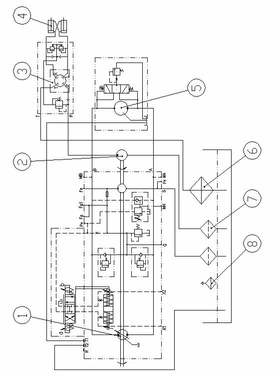
Figure 08 Hydraulic Diagram
1. Vibration pump 2. Steering pump 3. Steering gear 4. Cylinder
5. Vibration motor 6. Radiator 7. Filter 8. Air cleaner
The hydraulic steering system is composed of gear pump, hydraulic steering gear, two duo-action cylinders, oil tank, pipes, etc. The system is of open loop. The steering gear and the valve block are two separate parts for the safety of steering system. Overload protection is provided and vibration of steering wheel can be prevented when external shock is encountered.
Two cylinders are articulated between the front and rear frames for steering.
The roller can turn left or right when the operator turns the steering wheel.
Hydraulic speed control is for changing the travel speed through hydraulic device. The system consists of gear pump, high pressure filter, transmission, radiator, etc. The gear pump is driven directly by the engine. Oil pump draws oil via the suction filter (primary filter) at oil pan in the transmission and supplies the oil to the high-pressure filter (fine filter). The oil from the high-pressure filter flows to the operating via the pressure-setting valve.
The hydraulic oil used in the system is anti-abrasion gear oil 15W/40. The oil in the oil tank should be changed every half-year or 1000 operation hours. When changing oil, drain the old oil thoroughly, and then fill the filtered clean oil until the oil stick can touch the oil (about 18~20 liters of oil is needed). The high-pressure filter element should be changed at the same time. Refer to the transmission user’s manual for operation and maintenance of transmission.
9. Electrical system
The electrical system consists of 4 parts: 1. generator/starter; 2. control system; 3 lighting system; 4. alarming system. Refer to Figure 09 for electrical diagram.
The generator/starter has two functions, one is to start the engine, and the other is to charge the battery when the engine is running.
The battery is maintenance-free battery. Two batteries are connected in series. The line voltage is 24V. The battery is mounted at the rear left of roller.
The function of control system is to control the instruments, gauges and lamps. The main power switch is at the left of toolbox. It controls the ON/OFF status of the electricity in roller. Other instruments are in the dashboard in the cab.
Lighting system is for providing brightness in cab and in the working field in night or for bad weather. Lamps are mounted at the front, back and top of the roller.
Alarming system is for warning the operator and spectator and avoiding accident. It includes horn, turning lamps, transmission oil filtration indicator and gauges.
When the transmission oil filtration indicator is ON, the filter is too dirty and the element must be replaced or cleaned.
The fuel level gauge is mounted on the dashboard. Fuel must be filled when the pointer is close to “0”. Refill the fuel before the fuel tank is empty.
Brake air pressure gauge indicates the brake air pressure. Make sure the pressure is not lower than the permitted limit before working. Inspection is needed if the pressure is too low. Otherwise, don’t run the roller.
The ordinary oil temperature of transmission should be 45℃-65℃, and the highest temperature is 80℃.
The ordinary oil pressure of transmission should be 1.3-1.6Mpa.
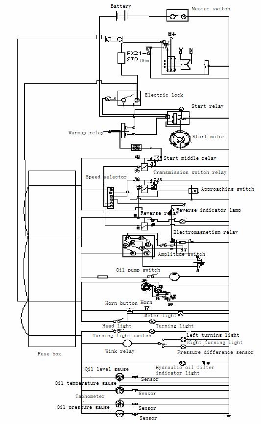
Figure 09 Electrical Diagram
Chapter 5 Operation Mechanism and instrument
1. Operation Mechanism
 |
Figure 10 Operation mechanism and instrument
1. Engine shutoff pull knob 2. Parking brake lever 3. Speed control box
4. Engine throttle control lever 5. Service brake pedal 6. Electric lock
7. Ignition switch 8. Vibration switch 9. Amplitude selector
10. Right turn indicator 11. Transmission oil temperature gauge 12. Transmission oil pressure gauge
13. Engine oil pressure gauge 14. Air pressure gauge 15. Transmission oil filtration indicator
16. Tachometer 17. Reverse gear indicator 18. Coolant temperature gauge
19. Left turn indicator 20. Ammeter 21. Engine oil temperature gauge
22. Fuel level gauge 23. Horn button 24. Turning lamp switch
25. Front lamp switch 26. Rear lamp switch 27 Main clutch pedal
28. Steering wheel 29. Seat 30. Main power switch
2. Instrument
|
Item |
Description |
Function |
|
1 |
Engine shutoff pull knob |
Pulling the knob to shut off the engine |
|
2 |
Parking brake lever |
Pulling to brake the transmission output (after the roller is stopped) |
|
3 |
Speed and direction control box |
Speed selector is at left and direction controller right. Middle is the neutral position; shift left and push to get gear I, Ⅱ, Ⅲ orderly, shift right and push to get gear Ⅰ, Ⅱ, Ⅲorderly. |
|
4 |
Engine throttle control lever |
Pushing forward to accelerate and backward to decelerate |
|
5 |
Service brake pedal |
Depressing to brake the vehicle |
|
6 |
Electric lock |
Inserting key and turning right for powering up |
|
7 |
Ignition switch |
To start engine |
|
8 |
Vibration switch |
Pushing rightward to start vibration and returning to stop |
|
9 |
Amplitude selector |
Pushing leftward for high amplitude and rightward for low amplitude, middle position for stopping vibration |
|
10 |
Right turn indicator |
To indicate the direction of turning |
|
11 |
Transmission oil temperature gauge |
45℃-60℃. Peak value is 80℃ |
|
12 |
Transmission oil pressure gauge |
Normal range is 1.3-1.6 Mpa |
|
13 |
Engine oil pressure gauge |
160-270Kpa. The minimum limit is 50Kpa when the engine runs at 500-600r/min. |
|
14 |
Air pressure gauge |
Indication range is 0.6-0.75MPa. |
|
15 |
Transmission oil filtration indicator |
Filter element must be replaced when the indicator is ON |
|
16 |
Tachometer |
To indicate the engine speed (800-2000r/min)(controlled by throttle) |
|
17 |
Reverse gear indicator |
To show that reverse gear is selected when the indicator is ON |
|
18 |
Coolant temperature gauge |
Normal reading range is 75℃-85℃, maximum limit is 95℃, minimum limit is 40℃ |
|
19 |
Left turn indicator |
To indicate the direction of turning |
|
20 |
Ammeter |
To show amperage (0-13A) |
|
21 |
Engine oil temperature gauge |
75℃-85℃,peak value should not exceed 120℃ |
|
22 |
Fuel level gauge |
To show fuel level in the fuel tank. Fuel should be refilled when the value is close to “0” |
|
23 |
Horn button |
To play the horn. Do it before starting engine. |
|
24 |
Turning lamp switch |
To switch the lamp ON when making turning |
|
25 |
Front lamp switch |
To turn ON/OFF the front working lights |
|
26 |
Rear lamp switch |
To turn ON/OFF the rear working lights |
|
27 |
Main clutch pedal |
Depressing the pedal to stop travel while engine is running. Slowly release the pedal to make the roller move stably |
|
28 |
Steering wheel |
Turning CW for right turning and CCW for left turning |
|
30 |
Master power switch |
It is the master switch for the whole machine. It must be turned off during maintenance. |
Chapter 6 Operation
1. Preparation before starting the engine
For normal operation of roller, check the following items before working. Solve the problem if any.
1.1 Make sure each fastener is tightened, especially at the places such as articulation, drum connection, rim, etc.
1.2 Make sure that the level of lube in engine pan and the fuel level are in specified range.
1.3 Check to see if the master power switch is turned ON. Check to see if the air inlet of engine is blocked.
1.4 Check if the oil level in hydraulic tank is in specified range and make sure there is no leakage at the oil pipes.
1.5 Check to see if the lubricant in each part is deteriorated after long period of storage. Change the oil if necessary. Refill the lube according to the lubricant requirements. Make sure the oil pipes are not blocked.
1.6 Make sure there is enough brake fluid in the brake cup and the clutch cup.
1.7 Adjust the seat so that the operator can easily operate and control each system.
1.8 Make sure that the electrical system, wiper, front/rear lamps are in good condition.
2. When starting the engine
2.1 Apply the parking brake.
2.2 Shift the speed selector in the neutral position.
2.3 Turn off the vibration switch.
2.4 Make the clutch disengaged.
2.5 Push the throttle rod to the Start (no load) position (about 800-1000rpm)
2.6 Insert the key and turn it ON.
2.7 Check the fuel level gauge and ammeter. When they are normal, press the start button to start the engine, and then release the button. If the engine fails to get started, repeat the above steps after 1 minute. The continuous starting time should not exceed 10 seconds.
2.8 Warm up the engine for 5-10 minutes after engine is started. Read the gauges and pay attention to the engine running. (Refer to the engine user’s manual)
2.9 Read the engine user’s manual when the engine is to be started in low temperature.
3. Travel and vibration
3.1 Release
the parking brake. Depress the clutch pedal to disconnect the power.
Select the gear needed and then release the clutch pedal so that the
roller moves.
Note: do not start to move the vehicle at gear 3 (maximum
speed). It should be changed from gearⅠ to
gearⅡ,
then to gearⅢ.
Wait 3 or 4 seconds after the clutch is disengaged before selecting
speed. Do same steps when changing from high speed to low speed.
3.2 Make sure that the emergency brake and the steering are reliable before traveling.
3.3 Pull
the throttle control lever to its maximum limit (engine runs at
2000rpm) and select the amplitude before vibration. High amplitude
for compacting primary base and low amplitude for secondary base.
Note: do not vibrate on hard ground since it may damage the
bearing. Wait 1 or 2 minutes when switching from high amplitude to
low amplitude.
3.4 When changing the travel direction of roller, stop vibration to protect the ground.
3.5 Pay attention to the readings of gauges during vibration to see if they are in normal range. The hydraulic oil temperature must be below 85℃.
4. Braking
4.1 Don’t have to depress the brake pedal when traveling on a straight and smooth road. Depress the clutch pedal to make the clutch disengaged when attempting to stop the roller.
4.2 When emergency braking is needed, depress the clutch pedal to cut off power, and then depress the brake pedal to stop the roller.
5. Stopping and parking
5.1 Turn the vibration switch to its middle position for stopping vibration.
5.2 Depress the main clutch pedal to disengage the main clutch. Shift the speed selector in the neutral position.
5.3 Put the throttle control lever to the idle position and run the engine for 3-5 minutes.
5.4 Pull the engine shutoff knob until the engine stops.
5.5 Turn the key to “0” position.
5.6 Apply the parking brake.
5.7 The roller should be parked on a flat ground at the side of road. If it has to be parked on a slope, use stones or similar objects to block the wheels and drum.
6. When to be towed, lifted or transported
6.1 To be towed
1) Shift the speed selector in neutral position when it is to be towed.
2) Release the parking brake.
3) Put the drag rope in front or rear drag hook.
Note: the maximum towing speed is 3km/h; the maximum towing distance is 1km.
6.2 To be Lifted
1) Lock the articulating frame.
2) Mount
the hanging frame in each slinger ring.
Note: do not press any part of the roller, as it may cause
deformation.
3) The slinger ring, pulley, chain, steel rope must be safe and reliable.
4) After the lifting is finished, demount the articulating frame lock and put it back to its original position before staring engine.
6.3 To be transported
1) The roller can be transported by itself at gearⅡor Ⅲ for short distance according to the road condition.
2) It should be carried by flat truck for long distance.
Note: lock the frames with tightening parts to prevent the
relative movement between frames when the roller is to be lifted or
transported. The roller must be firmly secured on the truck.
7. Clean and store the roller
7.1 Clean the roller
Eliminate the dirt and dust on the roller after daily work is finished. Pay more attention to clean the engine, generator, starter motor, high pressure pump, fuel injector, hydraulic pump and motor, hydraulic pipes, and exterior surface. Use dry and soft cloth to clean these parts.
If the roller is to be stored for long time, drain the water from the coolant tank. Carefully eliminate the dirt and dust. Use kerosene to clean the surface of each part and each lubrication hole and inject grease. Coat the unpainted outer surface with grease or anticorrosive coating.
7.2 Store the roller
The roller should be stored in a dry warehouse. If it has to be stored outside, the ground should be kept dry and the roller should be covered with waterproof cloth. If the roller is to be stored for long time, support the rear axle to get the tires off the ground and support the front frame to let the shock absorber relax. Start and run the roller at low speed for 10-15 minutes every three months.
Chapter 7 Maintenance
Timely and correct maintenance can assure satisfactory performance and working life for the roller.
1. Points to be checked at maintenance
 |
Figure 12 Points to be checked
1. Mud guard 2. Drum oil level plug 3. Vibration motor
4. Shock absorber and fasteners 5. Drum oil filling port 6. Drum oil draining port
7. Service brake 8. Parking brake 9. Hydraulic oil filter
10. Hydraulic oil draining port 11. Vibration pump/steering pump 12. Air cleaner
13. Fuel level 14. Fuel tank vent 15. Fuel supply pump
16. Fuel drain plug 17. Fuel filter and oil filter 18. Battery box
19. Battery box door 20. Rim bolts 21. Rim
22. Axle 23. Left hood 24. Brake fluid cup
25. Steering articulating frame 26. Rear hood 27. Fuel tank
28. Outer fuel filling port (air cleaner) 29. Right hood
2. Lubricant and hydraulic oil
2.1 Grease: lithium based grease
2.2 Engine oil: 15W/40
Engine (refer to the engine user’s manual for the filling amount, approx. 24L)
Transmission (approx. 18L)
2.3 Hydraulic oil
Chinese brand: 46# anti-abrasion hydraulic oil (filled by roller manufacturer before delivery).
Overseas brand: T68 anti-abrasion hydraulic oil (filled after the old oil is thoroughly drained when changing oil. Different oil should not be mixed in the tank.)
2.4 Lubricant:
Drum: 85W/90 (GL-5) lubricant (filling amount: 70 liters)
Rear axle: 85W/90 (GL-5) lubricant (filling amount: 25 liters)
2.5 Brake fluid
719 synthetic automobile brake fluid (1.2 liters filled)
To be used in clutch booster and brake system
3. Precautions for fuel system
The working life of diesel engine is significantly dependent on the purity of fuel.
l Keep the fuel pure and free from any impurities and/or moisture. Otherwise, the injector of engine may be damaged.
l Do not keep the fuel in the zinc-plated container.
l Keep the fuel container still for a while before opening the cap. Never roll the container for finding the oil plug before the fuel is sucked completely.
l Prevent the pipe from agitating the dregs in the fuel container.
l Prevent the fuel from spilling. The fuel should be stored in a safe place where no problem will be caused.
l When filling fuel is needed, open the cover of filter on the fuel tank and insert the pipe into the filter port.
l Check the precipitator periodically. Unscrew the plug at the bottom of precipitator to drain the water. Tighten the plug when oil starts to flow out.
4. Precautions for hydraulic system
Pay much attention to the cleanness while doing service. Be sure that no dust or dirt gets into the hydraulic system. Even tiny particle may cause abrasion in hydraulic parts and result in system breakdown.
l When the hydraulic oil level is found to be lower when doing daily inspection, check the pipes, connectors and other parts that are suspected to cause leakage.
l Stop the running of the components causing leakage.
l Hydraulic oil container should not be put outdoors because water may get into the container. If it has to be put outdoors, put a waterproof cover on it for protection.
l Place the oil container vertically for a while before the oil it to be sucked. Do not roll the oil container to filling area.
l To prevent the dust from getting into the oil, clean all parts and working area before oil is to be sucked.
l Use filter to fill the oil into the hydraulic system if possible.
l Cap the oil tank after filling is finished.
5. Items for periodic maintenance
Refer to the engine operation manual for engine maintenance.
5.1 Daily maintenance (every 10 operation hours)
5.1.1 Adjust the mud guard
a. Loosen the bolts on mud guard;
b. Make sure that the end of mud guard is 20mm from the drum;
c. Tighten the bolts on the mud guard.
5.1.2 Check the engine oil level (refer to the engine operation manual)
a. Move the roller to a flat ground and stop the engine;
b. Pull out the oil ruler to check the oil level;
c. If the oil level is lower than the specified mark, refill the oil. Never start the engine when the oil level is lower than the minimum limit (L) or higher than the maximum limit (H). When the oil level is to be checked, wait at least 5 minutes after the engine is stopped so that the oil has enough time to return to the oil pan. The volume between maximum and minimum limits is about 3.6 liters.
5.1.3 Check the hydraulic oil level
Move the roller to a flat ground and stop engine. Open the left hood to check the oil level in hydraulic tank. If the oil level is lower than normal value (scale “20” on the oil ruler), refill same hydraulic oil to the specified level.
5.1.4 Adjustment of parking brake
Make adjustment to keep the brake in good condition.
5.1.5 Fill fuel in the fuel tank
Fill fuel until it occupies 4/5 of the fuel tank volume every day. Use winter fuel in winter to avoid paraffin precipitation that will make the fuel more viscous.
5.1.6 Check the brake fluid level. Timely check the oil cup under the driver’s seat to make sure there is enough brake fluid.
5.2 Weekly maintenance (every 50 operation hours)
5.2.1 Clean the air cleaner (refer to the engine user’s manual for the steps of cleaning)
Clean it every 10-50 operation hours according to the quantity of dust. The air cleaner can be seen when the rear hood and right hood are opened. Prevent dust from getting into the filter. Make sure that no dust enters the air intake of engine. Tighten or replace the hose or other parts that may cause leakage. Use cloth to clean the internal surface of filter housing and the air intake. Make sure that the connecting parts and hoses between filter housing and engine are not damaged, and no leakage.
5.2.2 Check the hoses and connectors for leakage.
5.2.3 Check the oil level in drum
Move the roller to a flat ground and keep the plug 1 at the highest position. See Figure 13. If there is enough oil in the drum, the oil will flow out when the plug 2 is unscrewed.
 Note:
vibration shaft will be overheated if the oil in the drum is too
much or too little.
Note:
vibration shaft will be overheated if the oil in the drum is too
much or too little.
Figure 13 Check the oil level in drum
5.2.4 Check the shock absorber and bolts
Make sure that the absorber is not damaged and the bolts are tightened correctly. Replace with a new one if any flaw that is 20-25mm deep is detected in the absorber.
5.2.5 Lubricating the articulated joint. The four joint bearings at articulated joint are lubricated by greasing lithium based lubrication in the oil cup M10*1 (1,2,3,4 in Figure 14).Remain some lubrication at the ports to prevent dust entering. If lubricate can’t enter into the bearing, support the bearing with jack and then lubricate.
Figure 14 lubricating the articulated joint
5.2.6 Check the air pressure of tires
Check the air pressure of two tires with tire pressure gauge. Make sure the pressure is at 0.28 – 0.30Mpa.
5.2.7 Check the tightness of nuts on wheels
Check the tightness with 500Nm torque wrench. Screw it down if necessary.
5.2.8 Grease the steering cylinder mounting parts
After the articulated bearings are greased, inject enough grease to the fittings at both sides of steering cylinder. The grease should be injected in the bearings.
5.2.9 Grease the clutch isolation bearing
An oil cup can be seen at left side behind the hydraulic tank when the left hood is opened. Fill lithium based grease in it.
5.3 Biweekly maintenance
Clean the surface of hydraulic oil cooler.
Wipe off the dust and dirt on the surface of hydraulic oil cooler. Wash down the ventilation chunnel with the compressed air or high pressure water. It may be better if jetting with steam.
5.4 Monthly maintenance (every 250 operation hours)
5.4.1 Change the engine oil and replace the oil filter (refer to the engine operation manual for method of replacing)
Drain the oil when it is still hot because the impurities can be easily discharged. Unscrew the old filter, put some clean oil on the rubber pad of new filter and mount the new filter. Screw for additional half turn after the rubber pad is seated and contacts correctly.
Start the engine and check the engine oil pressure and airproof of filter. If air gets into the fuel system during replacing, the engine will not be able to be started. Bleed the air from the fuel system.
Make sure not to contaminate the oil when replacing the filter. After installation, start the engine and make sure there is no leakage around the filter.
5.4.2 Check the brake system
a. Check and solve the problem if the braking is not effective when the brake pedal is depressed.
b. Check the oil cup and connectors in the brake system for leakage.
c. Make sure there is enough brake fluid.
d. Make sure there is not internal leakage in the brake cylinder.
5.4.3 Check the transmission oil level
Before checking the oil level, be sure that the roller is placed in a level and flat ground. Stop for 5 minutes and let the oil return to the oil pan thoroughly. Then check the oil stick. The oil level should be between the maximum and minimum limits. Refill if the oil level is lower than the minimum limit.
5.4.4 Check the oil level in rear axle
Check the oil level in the master reducer and differential. Clean and unscrew the oil level plug. The oil level should be at the lower edge of the hole. If it is not enough, refill the oil until it overflows from the hole.
5.5 Quarterly maintenance (every 500 operation hours)
Refer to the engine user’s manual for adjusting the valve clearance.
5.6 Semiyearly maintenance (every 1000 operation hours)
5.6.1  Change
the oil in drum
Change
the oil in drum
Change the oil in drum
Place the roller on a slightly sloped ground and keep the drain plugs 1 and 2 at the lowest position. Unscrew the plugs 1 and 2 and drain the oil into a container. After the oil is thoroughly drained, move the roller to a leveled and flat ground and keep the plug 1 and 2 at the highest position. Then fill the new oil through the hole of plug 2. When the oil starts to flow from the hole of plug 3, screw the plug. The oil can’t be too much or too little. The oil level is checked at one side only because the oil chambers at two sides are through.
5.6.2 Discharge the deposit in the fuel tank
The water and deposit in the fuel tank can be discharged through the drain plug at the bottom of the tank. Do not start the roller for a period of time (one night) before discharging. Unscrew the drain plug to discharge the water and deposit. Stop discharging and screw the plug when clean diesel oil starts to flow out. It may be better if one side of the roller is a little higher than the other side because the deposit can be concentrated at one drain plug.
5.6.3 Bleed the air from the fuel system (refer to the engine operation manual).
5.6.4 Replace the fuel filter
Clean the connecting place of filter and then demount the filter. Clean the washer of filter. Replace the O-ring seal. Fill clean diesel oil into the new filter. Oil the O-ring seal should be lubricated by clean engine oil.
Note: mount the fuel filter. Screw for additional 1/2 or 3/4 turns after the seal is well contacted. Over-tightening may damage the thread or seal.
5.7 Yearly maintenance (every 2000 operation hours)
Change the oil in hydraulic tank.
Pay attention to the specifications, quality and purity of oil when servicing the hydraulic system. These factors are very important to the normal operation and working life of roller. Use the filling trolley with 10μfilter to fill the hydraulic oil and observe the following points:
5.7.1 Thoroughly clean the outer surface of hydraulic tank. Prevent foreign material from falling into the tank when opening the cap.
5.7.2 Use clean brush or cloth from which no hair will be fallen if the hydraulic tank has to be cleaned.
5.7.3 It is better to drain the oil when it is hot because hot oil has better liquidity and solubility and the deposit may be discharged more easily.
5.7.4 46# anti-abrasion hydraulic oil (Chinese brand) is recommended. Do not use other type of oil without roller manufacturer’s written permission. Different oil must not be mixed.
5.7.5 Air-tightness should be ensured after the hydraulic tank is cleaned. No oil leakage is permitted. Sealant 601 or Loctite should be used on the sealing face to ensure air-tightness.
5.8 Engine maintenance
Refer to the engine user’s manual for engine maintenance.
5.9 Air conditioner (optional) maintenance
Refer to the air conditioner user’s manual for it maintenance.
5.10 Transmission maintenance
Refer to the transmission user’s manual for its maintenance.
Chapter 8 Troubleshooting
1. Transmission
1.1 Gear down
When the pressure decreases, the speed is down without manipulating the speed selector. The cause may be:
a. Deficiency of oil; and/or
b. Air gets into the pipe; and/or
c. Problem with speed selector.
1.2 Oil leakage
Track the leaked oil to find the part that causes leakages. The cause may be:
a. Wearing-out and aging of seal; and/or
b. Wearing-out of shaft which contacts seals; and/or
c. Drain plug is loosened; and/or
d. Transmission case is cracked.
Take care of the lip of seal during mounting and prevent it from being damaged by thread or shoulder on shaft. Remember to lubricate the shaft before inserting. Refer to the transmission user’s manual for transmission troubleshooting.
1.3 Invalid braking
The cause may be:
a. Clogged oil pipe or deficiency of oil; and/or
b. Brake fluid spoiled or contains impurities; and/or
c. Oil pipe is cracked or there is air in the oil line; and/or
d. Internal leakage in brake cylinder or brake valve.
2. Drum
The possible problem with drum may be overheating and/or oil leakage. The overheating will burn the bearings on the shaft. The cause for overheating may be:
1.1 Too little or too much lubricant. The oil in the drum is used for not only lubricating, but also cooling the bearing. Insufficient oil will not provide enough cooling and the oil film on bearings will be destroyed in high temperature and the bearings will be burnt. Too much oil will produce mist when the eccentric block runs at high speed and high frequency. Intensive collision among the molecules will cause overheating and the bearings will be burnt.
1.2 The radial clearance and the end play of bearing are too little. Thermal expansion may make the clearance even less and the overheating may burn the bearing. Strictly follow the instruction to fill the oil. Oil leakage is usually caused by failure of seal or looseness of bolts. If the seal at the end of vibration motor shaft fails, the hydraulic oil in the motor will be leaked to the drum. In this case, check to see if there is any hydraulic oil in the drum. Change the oil in drum if two kinds of oil are mixed, otherwise the oil will be deteriorated and seals and bearings will be damaged by high temperature.
3. Vibration hydraulic system
These components (valve, pump and motor) will work in high temperature. The parts are produced and assembled with high accuracy. Disassembly should not be done by customer if the test equipment and necessary instruments are not available. Customer must not adjust the pressure setting when there is not pressure gauge.
When there is not complement pressure in the vibration pump, please check the oil level and the complement pipe. If the complement pressure is not enough, replace the inlet oil filter element. If only one amplitude is available, please make sure the electromagnetic switch is activated in place. Then check the pressure at the high pressure side. If the pressure is too low, it may be caused by the internal leakage in the system or low setting value in the pressure regulator valve. It is necessary to check the valve block in the system. If vibration can not be performed while the pressure is high, check the installation of drum and splined sleeve. If the vibration frequency is not enough, ask the qualified service engineer to adjust the displacement of pump until the requirements are satisfied.
////////////////////////////////////////////