SiteSentinel iTouch Tank Monitoring System. Installation Manual
SiteSentinel® iTouch™
Tank Monitoring System
Installation Manual
Table of Contents
1 Introduction
10
1.1
Warnings
10
1.1.1 Safety
10
1.1.2 Fire and Explosion Hazard
10
1.1.3 Dangerous Voltages
10
1.1.4 Compliance
10
1.1.5 Precision Leak Test
10
1.1.6 Initial Inspection
11
1.1.7 Connect Internal Battery
11
2 Specifications
12
2.1
SiteSentinel® iTouch™ Controller
12
2.2
Printer
13
3 Magnetostrictive Probe (Model 924B)
14
3.1
About the Probe
14
3.2
Probe Specifications
15
3.3
Probe Lengths/Installation Scenarios
16
4 Controller Installation
17
4.1
Mounting the Controller
17
4.2
Mounting the Optional Printer Bracket
18
4.3
Installing the Controller Power Supply Conduit
19
4.4
Wiring the Controller Power Supply
20
4.4.1 Grounding the SiteSentinel® iTouch™ Tank Gauging System
21
4.4.2 SiteSentinel® iTouch™ Port Protection
21
5 Preparing for Probe and Sensor Installation
23
5.1
Probe and Sensor Wiring
23
5.1.1 Compliance
23
5.1.2 Wire Type
23
5.1.3 Probe Wiring
23
5.1.4 Sensor Wiring
23
5.1.5 Wire Length
23
5.1.6 Wire Splices
23
5.2
Conduit
24
6 Seal-Offs
25
6.1
Junction Boxes
25
7 Preparing Your Tanks for Probes
26
7.1
Underground Tank Manholes
26
7.2
Precision Leak Test
27
7.3
Probe Placement
27
8 Product Float and Water Float Offsets
28
8.1
Offset Procedure
28
8.1.1 Float Offset Example
28
8.2
Calculating Tank Tilt and Offset Factor
29
9 Probes
30
9.1
Probe Floats
30
9.1.1 Product Level vs. Water Level
30
9.1.2 Water Float Weight Specification
30
9.1.3 Installing the Float(s)
30
10 Product Density & Chemical Compatibility
32
10.1
Determining Water Float Product Group
33
Page 3 of 123
11 Part Numbers
34
12 Probes Wiring
35
13 Sensors
38
13.1
Before You Begin
38
13.2
30-3206 Interstitial Hydrocarbon Liquid/Water Sensor
38
13.2.1
About the 30-3206
38
13.2.2
Specifications
38
13.2.3
Installing the 30-3206
39
13.2.4
Connections
39
13.2.5
Typical Interstitial Hydrocarbon Liquid/Water Sensor Installation
40
13.2.6
SiteSentinel® iTouch™ Controller Setup for Interstitial (“IS”) Hydrocarbon Liquid/Water Sensor
40
13.2.7
1st IS Module Position - Hydrocarbon Liquid
40
13.2.8
2nd IS Module Position - Water
41
13.2.9
Testing and Decontaminating the Interstitial Hydrocarbon Liquid/Water Sensor
41
13.3
30-3207 Hydrocarbon Liquid Sensor
42
13.3.1
About the 30-3207-06, -10, -15
42
13.3.2
Specifications
42
13.3.3
Installing the 30-3207-06, -10, or -15
42
13.3.4
Connections
42
13.3.5
Typical Hydrocarbon Liquid Sensor Installation
43
13.3.6
SiteSentinel® iTouch™ Controller Setup for Hydrocarbon Liquid Sensor
43
13.3.7
Testing and Decontaminating the Hydrocarbon Liquid Sensor
43
13.4
30-3210-06, -10, -15 Hydrocarbon Liquid/Water Sensor
44
13.4.1
About the 30-3210-nn
44
13.4.2
Specifications
44
13.4.3
Installing the 30-3210-06, -15, -20
45
13.4.4
Connections
45
13.4.5
Typical Hydrocarbon Liquid/Water Sensor Installation
46
13.4.6
SiteSentinel® iTouch™ Controller Setup for Hydrocarbon Liquid/Water Sensor
46
13.4.7
Hydrocarbon Sensor Configuration
46
13.4.8
Water Sensor Configuration
46
13.4.9
Testing the Sensor
47
13.5
30-3219-12 Hydrocarbon Liquid Sump Sensor
48
13.5.1
About the 30-3219-12
48
13.5.2
Specifications
48
13.5.3
Installing the 30-3219-12
49
13.5.4
Connections
49
13.5.5
Typical Hydrocarbon Liquid Sump Sensor Installation
50
13.5.6
SiteSentinel® iTouch™ Controller Setup for Hydrocarbon Liquid Sump Sensor
50
13.5.7
Testing and Decontaminating the Hydrocarbon Liquid Sump Sensor
51
13.6
30-3221-1 Single-Level Sump Sensor
51
13.6.1
About the 30-3221-1
51
13.6.2
Specifications
51
13.6.3
Installing the 30-3221-1
52
13.6.4
Connections
52
13.6.5
Typical Single-Level Sump Sensor Installation
53
13.6.6
SiteSentinel® iTouch™ Controller Setup for Single-Level Sump Sensor
53
13.6.7
Testing the Single-Level Sump Sensor Float
53
13.7
30-3221-2 Dual-Level Reservoir Sensor
54
13.7.1
About 30-3221-2
54
13.7.2
Specifications
54
13.7.3
Installing the 30-3221-2
55
13.7.4
Connections
55
Page 4 of 123
13.7.5
Typical Dual-Level Reservoir Sensor Installation
56
13.7.6
SiteSentinel® iTouch™ Controller Setup for Dual-Level Reservoir Sensor
56
13.7.7
Testing the Dual-Level Reservoir Sensor Float
57
13.8
30-3221-1A, -1B Interstitial Level Sensors
58
13.8.1
About the 30-3221-1A, 1B
58
13.8.2
Specifications
58
13.8.3
Installing the 30-3221-1A, -1B
59
13.8.4
Connections
59
13.8.5
Typical Interstitial Level Sensor Installation
60
13.8.6
SiteSentinel® iTouch™ Controller Setup for Interstitial Level Sensor
60
13.8.7
Testing the Float Sensor
61
13.9
30-3222 Hydrocarbon Vapor Sensor
62
13.9.1
About Part #30-3222
62
13.9.2
Specifications
62
13.9.3
Installing the 30-3222
63
13.9.4
Connections
63
13.9.5
Typical Hydrocarbon Vapor Sensor Installation
64
13.9.6
SiteSentinel® iTouch™ Controller Setup for Hydrocarbon Vapor Sensor
64
13.9.7
Testing and Decontaminating the Hydrocarbon Vapor Sensor
65
13.10
30-3223 Interstitial Optical Liquid Sensor
66
13.10.1 About the 30-3223
66
13.10.2 Specifications
66
13.10.3 Installing the 30-3223
66
13.10.4 Connections
66
13.10.5 Typical Interstitial Optical Liquid Sensor Installation
67
13.10.6 Controller Setup for Interstitial Optical Liquid Sensor
67
13.10.7 Testing the Interstitial Optical Liquid Sensor
67
13.11
30-3224 Combo Single Level/Hydrocarbon Liquid Sump Sensor
68
13.11.1 About the 30-3224
68
13.11.2 Specifications
68
13.11.3 Installing the 30-3224
69
13.11.4 Connections
69
13.11.5 Typical Combo Single-Level/Hydrocarbon Liquid Sump Sensor Installation
70
13.11.6 Controller Setup for Combo Single-Level/Hydrocarbon Sump Sensor
70
13.11.7 Testing the Float Sensor Portion of the Combo Sensor
71
13.11.8 Testing and Decontaminating the Hydrocarbon Sensor Portion of the Combo Sensor
71
13.12
30-3225 Combo Dual Level/Hydrocarbon Liquid Sump Sensor
72
13.12.1 About the 30-3225
72
13.12.2 Specifications
72
13.12.3 Installing the 30-3225
73
13.12.4 Combo Sensor Connections
73
13.12.5 Typical Dual-Level Hydrocarbon Liquid Sump Sensor Installation
74
13.12.6 Controller Setup for 30-3225
74
13.12.7 Testing the Float Sensor Portion of the Combo Sensor
75
13.12.8 Testing and Decontaminating the Hydrocarbon Portion of the Combo Sensor
75
13.12.9 Testing the Water Sensor Portion of the Combo Sensor
75
14 External Device Connection
76
15 RJ-45 Communication Ports
77
16 Terminal Block Detail
78
17 Printer Option
79
17.1
Modem Connections
80
18 CAP Connection for SiteConnect™ Software
81
18.1
POS Interface Option
81
Page 5 of 123
18.2
Built-in TCP/IP Connections
81
19 Appendix A - LCD Screen Icons
82
19.1
Sensor, Probe and Controller Status Icons
82
20 Appendix B - Alarm Kit Option
83
20.1
Alarm Kit Part Numbers
83
20.2
Installation
83
20.3
Alarm Kit Connections
84
21 Appendix C - POS Interface
85
21.1
SiteSentinel® iTouch™ POS Port
85
21.2
Prepare and Attach the Cable
85
22 Appendix D - Upgrading SiteSentinel® iTouch™ Software Via SiteConnect™
86
23 Appendix E - OM4 Output Module Option
88
23.1
Codes
88
23.2
Hazardous Area Definition
88
23.3
OM4 Output Module Specifications
88
23.4
Installing the OM4
89
24 Appendix F - LPG Probe Option
91
24.1
About the LPG Probe
91
24.1.1
30.1510 Probe Kit (Figure 41) Contents
91
24.2
30-1511 Probe Kit (Figure 24-2) Contents
92
24.2.1
Head Cover Kit (Figure 24-3) Contents
92
24.3
Installing the LPG Probe
93
25 Appendix G - Probe Comparison
95
25.1
Model 924 and 924B Magnetostrictive Probe Probe Comparison
95
25.2
Ordering the New Probe
95
25.3
Probe Installation
96
26 Appendix H - Hardware for SiteSentinel® iTouch™ Controller Main Board
97
26.1
Hardware Overview
97
26.2
Hardware Detail
99
26.2.1
Communication Ports
99
26.3
Status Indicators
100
26.4
Dip Switch
100
27 Appendix I - EPA Certifications
101
Index
123
List of Figures
Figure 2-1 SiteSentinel® iTouch™ Controller
12
Figure 3-1 924B Probe
14
Figure 3-2 Probe in Manhole-Equipped Tank
16
Figure 3-3 Probe in Tank With No Manhole
16
Figure 4-1 Mounting Footprint
17
Figure 4-2 Printer Bracket Mounting Dimension
18
Figure 4-3 Controller Conduit Knockouts
19
Figure 4-4 SiteSentinel® iTouch™ Ground Lugs
21
Figure 4-5 SiteSentinel® iTouch™ External Surge Protector (75-0104)
21
Figure 4-6 SiteSentinel® iTouch™ External Surge Protector I/O Port Connection (75-0104)
22
Figure 6-1 Creating a Seal-Off
25
Figure 7-1 Underground Tank Manholes
26
Figure 7-2 Probe Placement in Tank
27
Figure 8-1 Calculating Tank Tilt
29
Figure 9-1 Probe Component Locator
31
Figure 10-1 Determining Water Level Indicator Type
33
Figure 12-1 Probe Connections - TWO Conductor Shielded Cable
36
Figure 13-1 Interstitial Hydrocarbon Liquid/Water Sensor
38
Figure 13-2 Interstitial (IS) Hydrocarbon Liquid/Water Sensor Installation
40
Figure 13-3 Hydrocarbon Liquid Sensor
42
Figure 13-4 Hydrocarbon Liquid Sensor Installation
43
Figure 13-5 Hydrocarbon Liquid/Water Sensor
44
Figure 13-6 Hydrocarbon Liquid & Water Sensor Installation
46
Figure 13-7 Hydrocarbon Liquid Sump Sensor
48
Figure 13-8 Hydrocarbon Liquid Sump Sensor Installation
50
Figure 13-9 Single-Level Sump Sensor
51
Figure 13-10 Single-Level Sump Sensor Installation
53
Figure 13-11 Dual-Level Reservoir Sensor
54
Figure 13-12 Dual-Level Sump Sensor Installation
56
Figure 13-13 Part # 30-3221-1B
58
Figure 13-14 Part # 30-3221-1A
58
Figure 13-15 Interstitial Level Sensor Installation
60
Figure 13-16 Hydrocarbon Vapor Sensor
62
Figure 13-17 Hydrocarbon Vapor Sensor Installation
64
Figure 13-18 Interstitial Optical Liquid Sensor
66
Figure 13-19 Interstitial Optical Liquid Sensor Installation
67
Figure 13-20 Combo Single Level/Hydrocarbon liquid Sump Sensor
68
Figure 13-21 Combo Single-Level & Hydrocarbon Liquid Sensor Installation
70
Figure 13-22 Combo Dual Level/Hydrocarbon Liquid Sump Sensor
72
Figure 13-23 Combo Dual-Level & Hydrocarbon Liquid Sensor Installation
74
Figure 14-1 Connecting External Devices to the Controller
76
Figure 14-2 Dip Switch for Modem Settings
76
Figure 15-1 SiteSentinel® iTouch™ RJ-45 Communication Ports
77
Figure 16-1 SiteSentinel iTouch Terminal Block Connections
78
Figure 20-1 External Alarm Wiring
83
Figure 21-1 Pinout for POS-to-SiteSentinel® iTouch™ Cable
85
Figure 23-1 SS1-to-OM4 Connection
89
Figure 23-2 DIN Connector Access
89
Figure 23-3 OM4 Output Module Wiring
90
Figure 23-4 Address Jumper for #2 OM
90
Figure 24-1 What's Supplied in the 30-1510 Kit
91
Figure 24-2 What's Supplied in the 20-1511 Kit
92
Figure 24-3 30-1512 Head Cover Kit Contents
92
Figure 24-4 Probe Assembly and Installation Overview
93
Figure 25-1 924 vs. 924B Probe Head
96
Figure 25-2 Top Stabilizer
96
Figure 25-3 Top Clip
96
Figure 25-4 Lower Stabilizer and Clip
96
Figure 26-1 SSI Board (0322)
97
Figure 26-2 Communication Ports
99
Figure 26-3 Power Supply
99
Figure 26-4 Status Indicators
100
Figure 26-5 DIP Switch
100
List of Tables
Table 5-1 Probe Quantity vs. Conduit Capacity
24
Table 10-1 Product Compatibility
32
Table 10-2 Product Compatibility (continued)
32
Table 11-1 Part Numbers
34
Table 12-1 I.S. Interface Module Connections to Belden TWO-CONDUCTOR Cable with Shield
35
Table 12-2 I.S. Probe Connections to Belden THREE-CONDUCTOR Cable
35
Table 13-1 Interstitial Hydrocarbon Liquid/Water Sensor Wiring
39
Table 13-2 Hydrocarbon Liquid Sensor Wiring
42
Table 13-3 Hydrocarbon Liquid/Water Sensor Wiring
45
Table 13-4 Hydrocarbon Liquid Sump Sensor Wiring
49
Table 13-5 Single-Level Sump Sensor Wiring
52
Table 13-6 Dual-Level Reservoir Sensor Connections
55
Table 13-7 Interstitial Level Sensor Wiring
59
Table 13-8 Hydrocarbon Vapor Sensor Wiring
63
Table 13-9 Interstitial Optical Liquid Sensor Wiring
66
Table 13-10 Combo Single-Level/Hydrocarbon Sensor Wiring
69
Table 13-11 Combo Dual-Level/Hydrocarbon Liquid Sump Sensor
73
Table 17-1 Printer DIP Switch 1 Settings
79
Table 17-2 Printer DIP Switch 2 Settings
79
Table 17-3 Printer DIP Switch 3 Settings
80
Table 20-1 External Alarm Relay Specifications (NOT Supplied)
83
Table 20-2 Alarm Kit Connections
84
Table 23-1 Wiring Connections for Alarm Kit
88
Table 25-1 924 Probe Conversion Chart
95
Table 26-1 Comparison chart of the current (0320) and new (0322) SiteSentinel iTouch main board
98
Page 9 of 123
1 Introduction
This manual describes the installation procedures for the SiteSentinel® iTouch™ Integrated Monitoring System.
Included in this manual are installation instructions for the Controller, probes and sensors.
1.1 Warnings
1.1.1 Safety
When working in an environment containing fuel and fuel vapors, there is ALWAYS a
risk of fire and explosion.
TO AVOID SEVERE INJURY OR DEATH, KEEP ALL POSSIBLE IGNITION
SOURCES AWAY FROM HAZARDOUS AREAS.
1.1.2 Fire and Explosion Hazard
Disconnect power before installing. DO NOT install this equipment in a volatile,
combustible or explosive atmosphere (the “hazardous area” defined in the National
Electrical Code).
1.1.3 Dangerous Voltages
Certain components have DANGEROUS voltages even with the power cord
disconnected.
Many of the procedures described in the following pages must be followed for each
tank that is to be included in the system. Please read the directions carefully before
proceeding.
Improper installation may endanger installers and users of this equipment!
Read these instructions CAREFULLY.
Installers must know the requirements of intrinsically safe devices, and must
strictly obey instructions in this manual to perform a safe installation.
1.1.4 Compliance
Installation must comply with the National Electrical Code (NFPA No. 70) and the Autom
Service Station Code (NFPA No. 30A).
Follow all of your local or regional codes, as well.
A fuel tank is a hazardous area as defined in the NEC. Do not mount any part of the system, or any
external devices (other than probes or sensors) within or above the hazardous area.
1.1.5 Precision Leak Test
A precision leak test should be performed on each tank - especially older ones - before installing the
SiteSentinel® iTouch™. This test makes sure that leak data generated by the system is accurate and reliable. A
pressurized precision leak test can be done on a tank after the probe has been installed, but DO NOT let the
pressure exceed 20 psi.
Page 10 of 123
1.1.6 Initial Inspection
The packing list contains details about your system. It is packed in the box with this manual. Store this sheet in
a secure location. Be sure to check the packaging carefully for any damage that might have occurred during
shipping.
1.1.7 Connect Internal Battery
For shipping, the internal battery in the Controller is disconnected. To activate the internal battery, remove the
yellow strips.
Page 11 of 123
2 Specifications
“I.S.” (Intrinsically Safe) Interface Module refers to the sealed “terminal strip” inside the Controller. “I.S.
Interface Module Position” refers to one (1) set of three (3) screw terminals on this terminal strip (for
power, signal and ground connections). Each I.S. Interface Module contains four “positions.”
2.1 SiteSentinel® iTouch™ Controller
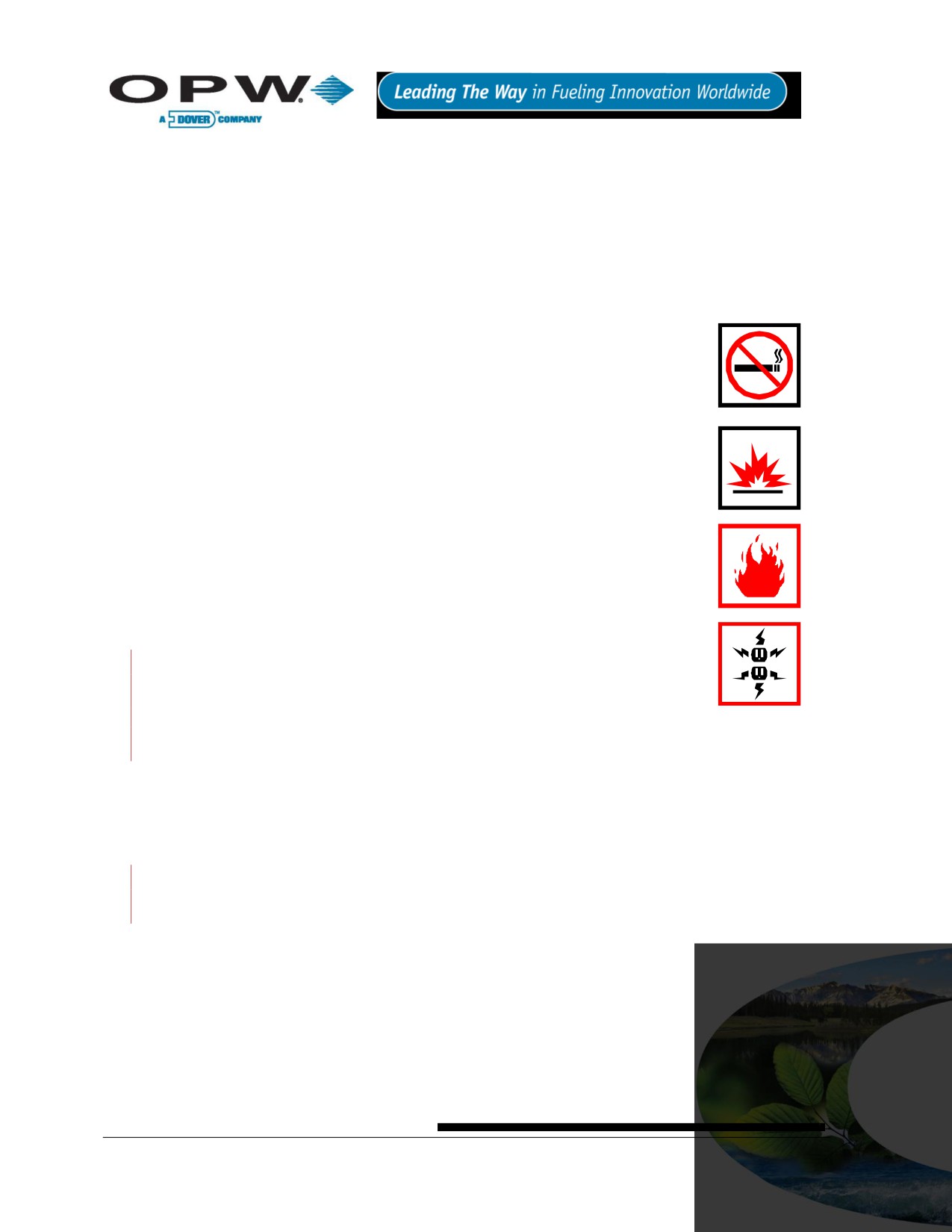
Figure 2-1 SiteSentinel® iTouch™ Controller
Physical Dimensions:
Height: 23.5 cm (9.25 in)
Width: 31.1 cm (12.25 in)
Depth: 13.3 cm (5.25 in)
Power Input:
100-250 VAC, 50/60 HZ, 1.0A
Operating Temperature Range:
0°C - 40°C (32°F - 104°F)
Remote Alarm Output:
Contact Rated at 30 VAC/DC 2A
Probe and Sensor Capacity:
16 probes and/or sensors
I.S. Interface Module:
14.5 VDC, 220 mA, 6.4 uF, 6 m
Optional Output Module OM4:
See Appendix E - OM4 Output
Option on page 88.
MOUNT THE CONTROLLER AND PRINTER OUTISDE THE HAZARDOUS AREA!
Substituting components will impair intrinsic safety.
For connection to intrinsically safe devices used in EEX ia IIA T4
(IEC/CENELEC) and Class 1, Division 1, Group D (North America) hazardous
locations.
For use ONLY with equipment specified in these installation instructions.
Document Nu
4
3
2.2 Printer
A thermal printer, the Seiko Model DPU-414, is available for reports and other printouts. See Figure 4-2 on
page18 for mounting instructions.
Physical Dimensions:
Height: 17.8 cm (7 in)
Width: 17.8 cm (7 in)
Depth (7.6 cm (3 in)
Power Input:
Provided by Controller
Operating Temperature Range:
0C° - 40°C (32F° - 104°F)
Page 13 of 123

3 Magnetostrictive Probe (Model 924B)
3.1 About the Probe
The 924B probe uses magnetostrictive principles
to derive product and water levels, and product
temperatures. These probes are primarily used
in underground storage tanks for both inventory
and leak detection.
Two floats can be fitted to the probe shaft: The
upper (product) float sits on top of the product,
and the lower (water float) sits on the
product/water boundary at the bottom of the
tank.
Five temperature sensors reside in the probe
shaft for measuring product temperature. They
are located at positions of approximately 10%,
20%, 40%, 60% and 80% of the tank volume
(based upon a cylindrical tank). The sensors
compensate for the expansion and contraction of
the product with temperature and thus produce
net corrected product volume.
Figure 3-1 924B Probe
Page 14 of 123

3.2 Probe Specifications
Operating Temp. Range:
-40°C - 60°C (-40°F - 140°F)
Head Dimensions:
With connector, 21.5 cm x 2.54 cm (8.5 in x 1
in)
Cable:
1.83 m (6 ft) of gas & oil-resistant cable
Sensor Power:
Must be provided by OPW Fuel Management
Systems’ I.S. Interface Module
Certifications:
North America: Class I, Division 1, Group D
Outside North America:
Ex ia IIA T4 Ga
DEMKO 11 ATEX 1012670X
IECEx UL 11.0012X
Level Resolution:
0.0127 mm (0.0005 in)
Temp. Sensor Resolution:
Less than +/- 0.3°C or 0.5°F
Special Conditions for safe use:
On devices supplied with 4-inch floats: to avoid build-up of static charge, do not rub with a dry cloth or clean in
any manner that would result in a charge build-up. Discharge outside of hazardous area before putting into
service.
These devices have not been evaluated for use across a boundary wall.
The upper housing cover in the top of the enclosure is aluminum. Care must be taken to avoid ignition hazards
due to impact or friction.
A probe for LPG tanks is also available. See Appendix F - LPG Probe Option on page 91.
Page 15 of 123

3.3 Probe Lengths/Installation Scenarios
Figure 3-2 Probe in Manhole-Equipped Tank
Figure 3-3 Probe in Tank With No Manhole
Page 16 of 123

4 Controller Installation
Choose a mounting location for the controller and printer. Choose an indoor mounting
location where it will be protected against moisture and extreme temperature and
humidity conditions.
Wall mount the controller at eye level close to a circuit breaker. Leave room above
and below controller for power, probe, sensor, remote alarm and other conduits that
must be connected to the controller.
If purchased, also leave room for the optional printer that normally mounts to the left of
the controller.
Do not mount the controller or external printer within or above the hazardous
area.
4.1 Mounting the Controller
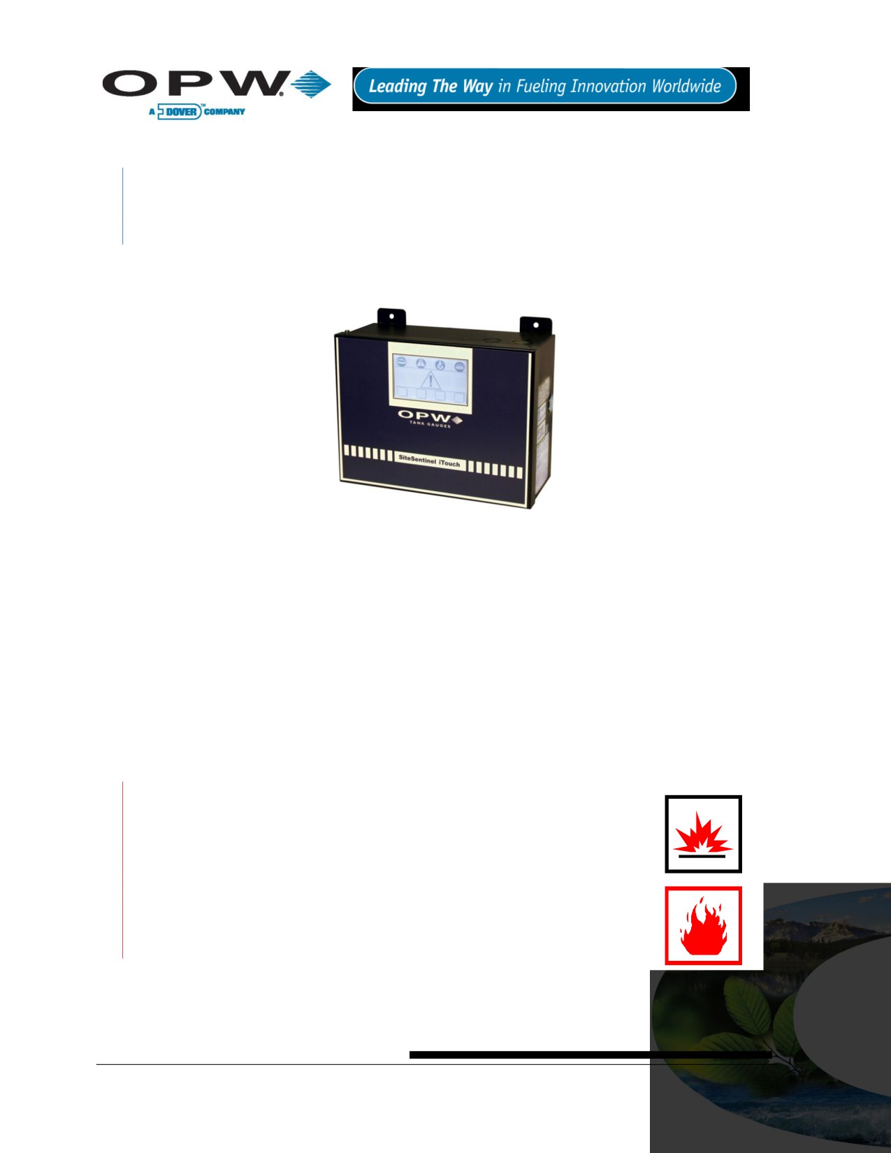
Mount the controller to the wall using the dimensions shown in Figure 4-1 below. The four
0.80 cm (0.315 in) diameter. Use as large a fastener as possible.
Do not drill holes in the SiteSentinel® iTouch™ cabinet.
3.5 cm
24.1 cm (9 1/2")
(1 3/8")
22.2 cm
(8 3/4")
23.5 cm
(9 1/4")
Intrinsically Safe
Intrinsically Safe
Interface Module
Interface Module
Intrinsically Safe
Intrinsically Safe
Interface Module
Interface Module
31.1 cm (12 1/4")
FRONT VIEW
with door attached
Figure 4-1 Mounting Footprint
Page 17 of 123
4.2 Mounting the Optional Printer Bracket
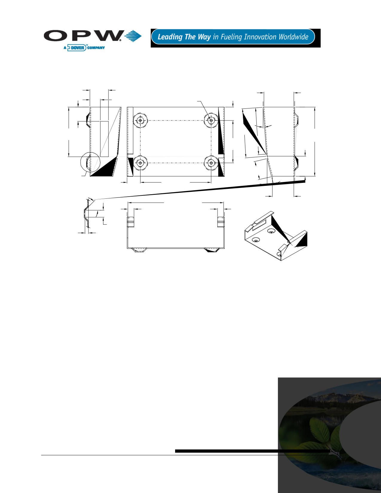
Mount the printer bracket to the wall using Figure 4-2, below. Holes are 0.56 cm (0.22 in). Use as large a
fastener as possible, but ensure that the fastener does not protrude past the recess in the bracket.
33.3mm
53 mm
(1 5/16")
(2 3/32")
4.5 mm
19 mm
inside
#16 Drill (.1770)
(3/4")
4 plcs.
25.4 mm
24 mm
(1")
(15/16")
4°
88mm
89 mm
(3 15/32")
12.4 cm
(3 1/2")
(4 7/8")
84mm
76 mm
(3 5/16")
(3")
36 mm
(13/32")
33.3 mm
Ref.
See
(1 5/16")
SK-A
24 mm
14°
12.7 cm (5")
Left Side
(15/16")
Front
38 mm
(1 1/2")
17.1 cm (6 3/4")
inside
45°
11 mm
inside
11 mm
Right Side
(7/16")
(7/16")
13 mm
6.4 mm
(1/2")
(1/4")
inside
Typ.
SK-A
Bottom
Figure 4-2 Printer Bracket Mounting Dimension
Page 18 of 123
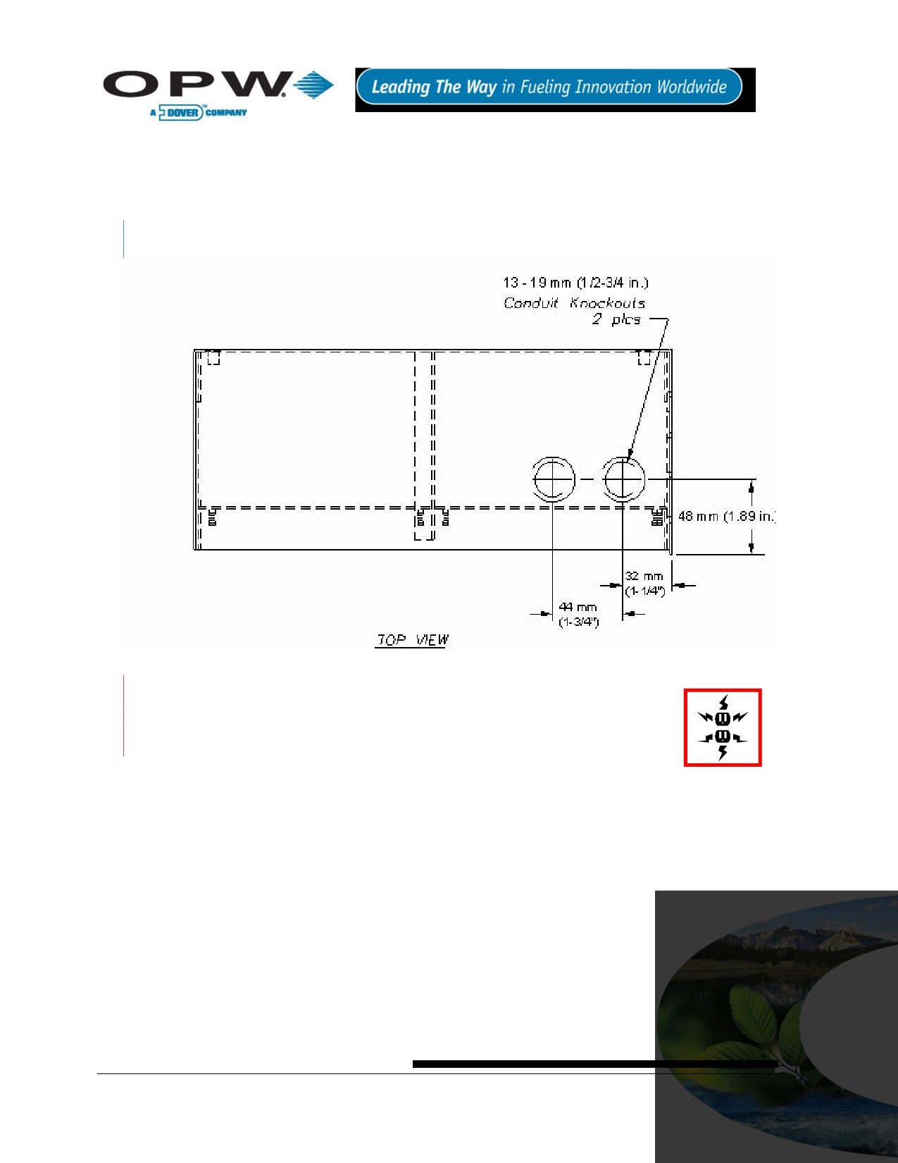
4.3 Installing the Controller Power Supply Conduit
A local circuit breaker/disconnect device must be installed close to the controller. Run conduit from this local
breaker back to the main site distribution panel. Install 13 mm (0.5 in) rigid steel conduit from the local circuit
breaker panel to the top right controller knockout, Figure 4-3 below.
The left knockout is reserved for optional external alarm wiring.
Figure 4-3 Controller Conduit Knockouts
Do not connect the controller to equipment that exceeds the maximum ratings of
voltage and current as specified in Specifications on page 13. Probe cables and
sensor wiring must not share conduit with any other wiring.
Page 19 of 123
4.4 Wiring the Controller Power Supply
The power supply automatically adjusts for supply voltages from 100 to 250 VAC
1. Pull two #14 AC power wires and one #12 AWG ground wire through the conduit from the distribution
panel to the local breaker dedicated to the controller.
2. Pull two #14 AC power wires and one #12 AWG ground wire through the conduit from the local
breaker to the controller.
3. Pull just enough wire through the bushing to attach to the 3-pin green terminal block located on the
right of the controller circuit board.
Connect AC neutral and AC hot wires (order not important) to pins 1 and 3 of the green terminal block.
Center pin is not used. Attach the cover to the terminal block.
4. Attach the ground wire to one of the ground terminal studs (near the top knockouts marked as ground)
and run back to the main distribution panel for connection.
The ground wire must be #12 AWG or larger.
Some countries/states require a redundant ground wire; this should be attached to the second ground
terminal stud and run back to the main distribution panel for connection.
Power wiring must enter the controller via the designated power conduit knockout.
Connect the power wires to a dedicated circuit.
See Specifications on page 12 for power requirements.
Protecting communication ports and ensuring site intrinsic safety for the SiteSentinel® iTouch™
Proper Grounding of the SiteSentinel® iTouch™ is essential for protecting the communication ports and
lessens the risks of hazardous situations occurring when power surges or lightning strikes happen. This
document outlines the recommended practices for a safe and damage-free installation.
Page 20 of 123
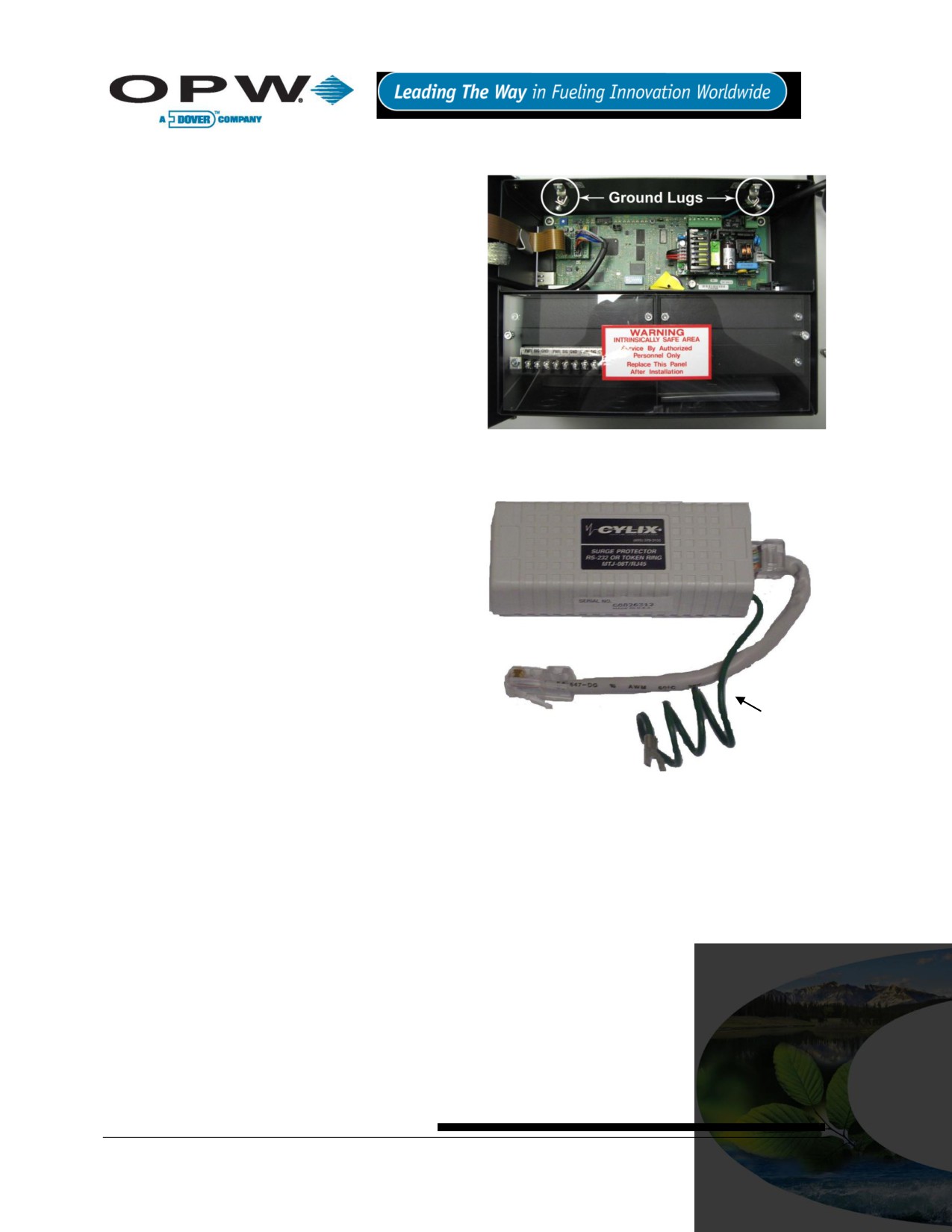
4.4.1 Grounding the SiteSentinel® iTouch™ Tank Gauging System
There are two ground lugs within the SiteSentinel®
iTouch™ (See Figure 4-4 below) You will need to
install two continuous ground wires (green 12 AWG or
larger) from both ground lugs connected back to the
distribution panel ground. The intrinsic barriers rely on
these ground connections; if they are not present the
barriers will not work. The redundant ground ensures
that the SiteSentinel® iTouch™ will operate properly
and safety.
4.4.2 SiteSentinel® iTouch™ Port
Protection
The communication ports can be damaged by ground
faults within the SiteSentinel® iTouch™. If you are
communicating from another type of system, such as a
Figure 4-4 SiteSentinel® iTouch™ Ground Lugs
point-of-sale (POS) system, to the SiteSentinel®
iTouch™ and there is a slightly ground potential
difference, this difference will either cause
immediate failure of the SiteSentinel® iTouch™, or
will cause a failure over time. To eliminate this
possible damage, make sure the other equipment
is grounded back to the same ground potential as
the SiteSentinel® iTouch™ at the distribution panel.
In addition, a 12 AWG or larger wire can be run
from the ground lug in the SiteSentinel® iTouch™
to the ground of the other equipment.
OPW Fuel Management Systems can supply an
external surge suppressor (Part # 75-0104), see
Figure 4-5 to the right. This device will help protect
the ports from power surges or lightning strikes.
Ground Wire
Figure 4-5 SiteSentinel® iTouch™ External Surge Protector (75-
0104)
Page 21 of 123

To install, simply insert the surge protector in series
between the incoming communication lines and the
I/O port of the SiteSentinel® iTouch™ (See Error!
eference source not found.). The surge protector
ground wire must be connected to the metal chassis
of the SiteSentinel® iTouch™ or to the ground lug
within the SiteSentinel® iTouch™. Each port requires
one surge protector.
Figure 4-6 SiteSentinel® iTouch™ External Surge
Protector I/O Port Connection (75-0104)
Page 22 of 123
5 Preparing for Probe and Sensor Installation
5.1 Probe and Sensor Wiring
5.1.1 Compliance
Installation of this equipment must be in accordance with all local, state and federal regulations pertaining to
this type of equipment including, but not limited to, the National Electrical Code, NFPA No. 70 and the
Automotive and Marine Service Station Code, NFPA No. 30A.
5.1.2 Wire Type
All wiring should have a capacitance rating of less than 100 picofarads per foot.
5.1.3 Probe Wiring
Gas and oil-resistant shielded, 2-conductor cable is required to extend the probe cable to the I.S. Interface
Module in the Controller. OPW Fuel Management Systems recommends you use Belden #88760 or Alpha
#55371 cable.
Belden #88760 is available directly from OPW Fuel Management Systems; part #12-1300
5.1.4 Sensor Wiring
You can use the same cable as used for the probe or you can use individual gas and oil-resistant cable,
providing it is 18 AWG or greater.
5.1.5 Wire Length
Wire runs must be less than 300 m (984 ft) to meet intrinsic safety standards. Also, wire lengths of 300 m (984
ft) or more between probe/sensor and the controller will jeopardize signal integrity and system operations.
5.1.6 Wire Splices
There should be no splices between the field junction box and the I.S. Interface Module in the SiteSentinel®
iTouch™ Controller. A splice in the hazardous area requires the use of a silicon-filled wire nut that must be
located in a waterproof junction box. Each splice would jeopardize signal integrity and system operations.
Page 23 of 123

5.2 Conduit
All probe and sensor cabling to the SiteSentinel® iTouch™ Controller must be in rigid steel conduit. The conduit
must be dedicated to intrinsically safe wiring for this controller.
Probe and sensor wiring for this controller can share the same conduit.
This controller’s intrinsically safe wiring cannot share the same conduit with other equipment’s intrinsically safe
wiring.
PVC conduit may be substituted for rigid steel conduit where acceptable by local codes. Use SHIELDED
cable for sensor and probe wiring as described in the above sections.
The size and number of probe and sensor conduits (probe sensor-to-controller) depends on how many probes
and sensors your site has.
See Table 5-1 below. Try to group probe wires into separate conduits for each SiteSentinel® iTouch™
Controller I.S. Interface Module position.
Table 5-1 Probe Quantity vs. Conduit Capacity
Number of Probes
Number & Size of Conduits
1 to 2
3 to 4
One 19 mm (0.75 in)
5 to 6
One 13 mm (0.5 in) and one 19 mm (0.75 in)
7 to 8
Two 19 mm (0.75 in)
9 to 12
Three 19 mm (0.75 in)
13 to 16
Four 19 mm (0.75 in)
Page 24 of 123

6 Seal-Offs
Seal off probe and sensor cables at both ends of the conduit run (Figure 6-1 below). Seal-offs prevent
explosive vapors from entering the controller or the building. Remove enough of the outer wire jacket to allow
approximately three (3) inches of wire leads to extend past each seal-off.
DO NOT nick the wire insulation.
SHIELDED CABLE
BELDEM #88760
OR ALPHA #55371
REMOVE 6" OF JACKET
AND FOIL. MAKE SURE
THE INSULATION ON
THE CONDUCTORS IS
NOT CUT AND THAT
THE GROUND WIRE IS
NOT BROKEN
TO PROBE/SENSOR
FROM PROBE OR SENSOR
MODULE
SEAL-OFF
SEAL-OFF
THE STRIPPED CABLE SECTION
MUST BE LOCATED WITHIN THE
SEAL OFF AREA.
#390198A5
Figure 6-1 Creating a Seal-Off
6.1 Junction Boxes
Weatherproof electrical junction boxes with a gasket-equipped cover are required at the end of each probe and
conduit run at the UST manhole or monitoring well location.
Wires coming off of a probe or sensor connect to prepared Belden or Alpha cable, and then go through an NPT
bushing into the weatherproof junction box. Bushings must be used in all junction boxes. The cable is then
routed out of the junction box via rigid steel conduit.
Page 25 of 123

7 Preparing Your Tanks for Probes
Figure 7-1 Underground Tank Manholes
7.1 Underground Tank Manholes
1. Excavate a 50 cm (20 in) minimum diameter manhole around an unused fitting in the top of the tank.
The hole must be big enough for a weatherproof junction box. If this fitting is not in the center of the
tank, you must take additional measurements for probe compensation (refer to Product Float and
Water Float Offsets on page 28).
2. Install a 7.5 cm - 10 cm (3 in - 4 in) diameter riser pipe in the fitting. This pipe must be long enough to
accommodate the probe head, and it must be large enough to accommodate the probe head, and it
must be large enough to accommodate the probe floats. Five cm and 10 cm (2 in and 4 in) floats are
available.
3. Install a weatherproof junction box with 13 mm (0.5 in) knockouts near the riser pipe. The junction box
must be close to the riser to allow the probe cable to reach.
4. Install a 13 mm (0.5 in) bushing in the junction box.
5. Install an adapter collar onto the tank’s riser pipe.
Use a riser cap with a suitable cable bushing installed. For older Model 924 and 613 probes, use a bushing
with an inner diameter of 11 mm (0.43 in). For next-generation 924, use bushings with an inner diameter of 5
mm (0.2 in).
Page 26 of 123

7.2 Precision Leak Test
Perform a precision leak test on each tank - especially older ones - before installing the SiteSentinel®
iTouch™. You can perform a pressurized leak test on a tank after probe installation; however, DO NOT exceed
20-psi pressure.
7.3 Probe Placement
Try to install the probe as close to the center of the tank (Figure 7-2, below) as possible. Locate the probe at
least 91 cm (about 3 ft) from the tank fill pipe. Adjust the drop tube of the fill pipe so that the product flow is
diverted away from the probe.
Figure 7-2 Probe Placement in Tank
Page 27 of 123
8 Product Float and Water Float Offsets
The 924 probes differ slightly in setup from previous models of probe. This section tells you how to match your
manual dipstick tank readings to the readings from the probe. Offset compensates for the angle (or slope) that
the tank may have.
When performing subtractions, remember that subtracting a negative number is the same as adding the
positive version of that number. For example, subtracting -2 from 6 results in 8.
8.1 Offset Procedure
An example appears below:
1. Run the SiteConnect™ software. Set both the Product Float Offset and the Water Float Offset held
in the SiteSentinel® iTouch™ Controller to zero (0).
2. Using your normal dipstick access point in the tank, take a Dipstick Product Level and a Dipstick
Water Level. To take the Dipstick Water Level, use water detect paste on the bottom of the dipstick.
3. Take an inventory reading from the controller. Note the Probe Product Level and the Probe Water
Level.
4. Calculate Product Float Offset and Water Float Offset:
5. Product Float Offset = (Dipstick Product Level - Probe Product Level)
6. Water Float Offset = (Dipstick Water Level - Probe Water Level)
7. Run SiteConnect™ software and configure the SiteSentinel iTouch Controller with the new offset
values obtained in the previous step.
8. Take an inventory reading from the controller. The Probe Product Level should now match the
Dipstick Product Level and the Probe Water Level should now match the Dipstick Water Level.
A typical Product Float Offset is 7.4 cm (2.9 in) and a typical Water Float Offset is 0 cm.
8.1.1 Float Offset Example
Sample DIPSTICK Levels
Product = 59.5
Water = 1.2
Sample PROBE Levels
Product = 56.6
Water = 1.5
Using this data and this equation: Dipstick Product Level = Probe Product Level = Product Float Offset,
the product offset value is 59.5 - 56.6, or 2.9.
Using this data and this equation: Dipstick Water Level - Probe Water Level = Water Float Offset, the water
offset value is 1.2 - 1.5, or -0.3
Page 28 of 123

8.2 Calculating Tank Tilt and Offset Factor
You can calculate a product offset for a probe that is not installed in the center of a “pitched” tank. Pitch is the
tilt of a tank along its horizontal axis. Some tanks are intentionally installed with one end lower than the other.
This allows water and sediment to collect at the low end, while clear product is drawn from the high end. Pitch
can also be caused by tank settling. The rate of pitch can be measured by using a dipstick to measure the level
of product at two points (preferably opposite ends) of the tank (See Figure 8-1 below). The product depth at the
deep (lower) end of the tank is value “A”. The product depth at the shallow (higher) is value “B”. The distance
between the two measuring points is “C”.
Figure 8-1 Calculating Tank Tilt
The formula for pitch is: (A-B)/C
For example: [(46” - 40”)/120”] = (6/120) = 0.05
To calculate the product offset, measure value “D”, the distance of the probe from the center of the tank. The
formula for product offset is “D” x pitch. For the example above, 36” x 0.05 = 1.8”
If the probe is located closer to the shallow end of the tank, the product offset is positive; for the example, 1.8. if
the probe is located closer to the deep end of the tank, the product offset is negative; for the example, 1.8.
See SiteConnect™’s Help for details about entering the product offset.
Page 29 of 123
9 Probes
This section covers gasoline and diesel probes. For information on the optional LPG (liquefied petroleum gas)
probe, see Appendix F - LPG Probe Option on page 91.
9.1 Probe Floats
The terms “float” and “level indicator” are completely interchangeable.
9.1.1 Product Level vs. Water Level
Figure 9-1 on page 31 shows how the probe components work together. The Product Level Indicator floats
atop the gasoline or diesel fuel and registers the overall height of the fuel. You can use the Product Level
Indicator with or without a Water Level Indicator.
The Water Level Indicator features one of two different ballast weights (color-coded for gasoline or diesel - see
Figure 10-1 on page 33). Because fuel products are less dense than water, the weight plate forces the Water
Level Indicator to sink through the product and float on the water. Water height at the product/water boundary
can thus be determined.
9.1.2 Water Float Weight Specification
If you ordered a Water Level Indicator the weight and fluid product group will be on a label affixed in the area
below. Each weight is certified by an OPW Fuel Management Systems technician for use with its Water Level
Indicator. The listed weight is the complete weight of the level indicator.
9.1.3 Installing the Float(s)
1. Review Figure 9-1 on page 31.
2. Remove the retaining ring from the probe shaft.
3. Install the level indicator(s) as shown.
4. Make sure the Water Level Indicator (if used) magnet faces UP.
5. Install probe end boot.
6. Make sure the Product Level Indicator magnet faces DOWN.
7. Replace the retaining ring through the slot in the probe end boot.
If the wrong type of water float is used, it may float to the top and register an unusually high water level,
not register at all or sink too far and register an unusually low water level. If your product fluid density
does not fit into one of these groups, contact the OPW Fuel Management Systems customer sales
department for recommendations.
Page 30 of 123


10 Product Density & Chemical Compatibility
Table 10-1 Product Compatibility
Product Group
Compatibility
API
Specific Gravity
Gasoline
Aviation Gasoline
Regular Unleaded
Regular Leaded
Gasoline (white core)
45 < API < 78
0.68 < d < 0.80
Premium Unleaded
Gasoline/Methanol blend,
less than 5% methanol
Gasohol, less than 40%
ethanol
Table 10-2 Product Compatibility (continued)
Product Group
Compatibility
API
Specific Gravity
Diesel
Jet Fuel
Kerosene
Motor Oil
Diesel (Black core)
26 < API < 45
0.80 < d < 0.90
Toluene
Gear Oil
Transmission Oil
If the float is used in a non-compatible fluid, swelling, cracking and dissolving may occur, leading to
failure. If your product is not chemically compatible with the floats, contact OPW Fuel Management
Systems Customer Service for recommendations.
Page 32 of 123

10.1 Determining Water Float Product Group
Figure 10-1 Determining Water Level Indicator Type
The Water Float/Level Indicator (Figure 10-1 above) features a ballast weight plate. This weight permits the
level indicator to sink through the product, but to float on the water, thus registering the height of the water at
the product/water boundary. The weight is certified by OPW Fuel Management Systems for use with one of the
two groups - gasoline group OR diesel group. You can tell which product the Water Level Indicator is for by the
color of the core (Figure 10-1). White cores are for gasoline, black cores are for diesel. There is also a mark on
the ballast weight plate (“G” for gasoline, “D” for diesel).
Page 33 of 123

11 Part Numbers
Table 11-1 Part Numbers
Item and Part #
30-1508-01
30-1508-02
30-1508-03
30-1509-01
30-1509-02
30-1509-03
Product level indicator assembly, 2
X
X
X
in (30-0113)
Water level indicator assembly, 2
X
X
in gas (30-0111)
Water level indicator assembly, 2
X
X
in diesel (30-0112)
Cable, 3 pole, 22 gauge, 6 ft, Blue
X
X
X
X
X
X
(10-1185)
Wire nut silicon-filled (10-5014)
X
X
X
X
X
X
Probe end boot (50-3092)
X
X
X
X
X
X
Page 34 of 123

12 Probes Wiring
Probe conduit must be dedicated to intrinsically safe wiring.
Use Table 12-1 below and Figure 12-1 on page 36 (for two-conductor cable) or Table 12-2 below and (for
three-conductor cable) to connect the probe to the Controller IS Interface Module terminal blocks.
See Figure 2-1 on page 12 for a probe drawing.
Table 12-1 I.S. Interface Module Connections to Belden TWO-CONDUCTOR Cable with Shield
I.S. Interface Module Terminal Position
Belden Cable
Probe Cable
+12 V
Red
Blue
(SIGNAL)
Black
Brown
Shield
Black & Shield
(GROUND)
Table 12-2 I.S. Probe Connections to Belden THREE-CONDUCTOR Cable
I.S. Interface Module Terminal Position
Belden Cable
Probe Cable
+12 V
Red
Blue
(SIGNAL)
Black
Brown
Shield
Black & Shield
(GROUND)
Page 35 of 123

Figure 12-1 Probe Connections - TWO Conductor Shielded Cable
With three-conductor cable, attach the shield from the cable ONLY TO THE CONTROLLER. Trim and tape
the other end of the shield. Do NOT allow the shield to touch any of the probe wires OR the metal
junction box.
Step-by-Step Procedure
1. Feed the blue probe cable through the bushing in the riser cap.
2. Attach the cable connector to the socket in the probe head.
3. Carefully lower the probe into the riser pipe until it rests on the bottom of the tank. Be careful not to
damage the floats.
4. Tighten the riser cap bushing, leaving enough cable to reach the junction box.
5. Snap the riser cap in place. Secure the cap with a lock.
6. Install a 13 mm (0.5 in) NPT bushing into the junction box.
7. Pass the probe cable through this bushing into the box, and then tighten the bushing.
8. Pull the shielded cable through the rigid conduit and through the installed seal-offs at both ends of the
conduit run. Leave slack in the probe wiring emerging from the ends.
9. Using the silicon-filled wire nuts included with the probe, connect the blue probe cable to the shielded
cable inside the electrical junction box.
10. Remove the clear plastic cover located over the I.S. Interface Modules inside the SiteSentinel®
iTouch™ Controller to attach the wiring from the probe conduit.
11. Connect the braided SHIELD from the Belden cable to the I.S. Module GROUND position.
12. Connect the BLACK wire to the I.S. Module SIGNAL position.
13. Connect the RED wire to the I.S. Module POWER position.
Page 36 of 123
When attaching probes to the controller, start with I.S. Module Position “1” and work toward “16.” Fill
one strip before starting another.
Write down which probe goes to each position. You will need this when you configure the SiteSentinel®
ITouch™ using the SiteConnect™ software.
Page 37 of 123
13 Sensors
13.1 Before You Begin
See local and National Electrical Codes for your location.
Ensure cabling (gas and oil-resistant OPW Fuel Management Systems part number 12-1030) back to
the controller is in conduit that is dedicated to intrinsically safe wiring.
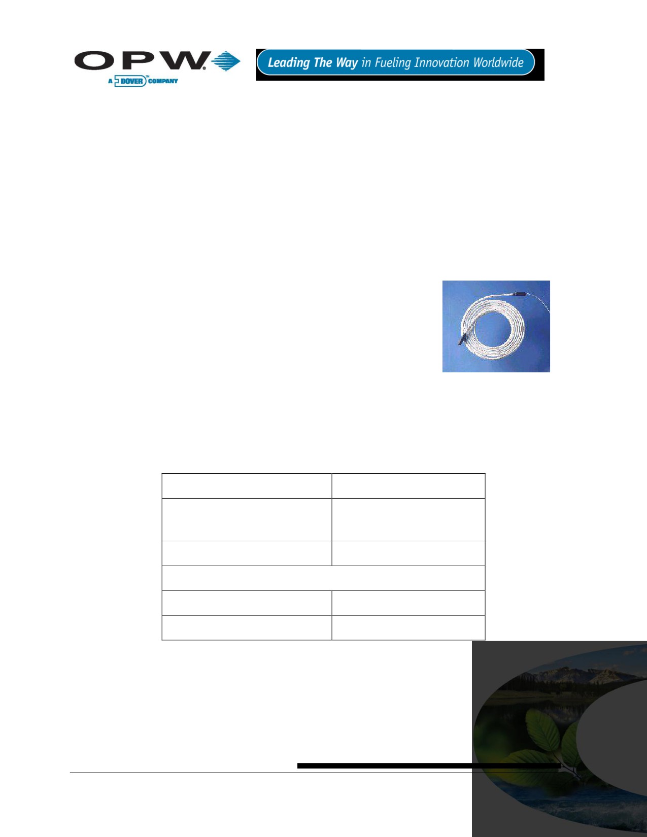
13.2 30-3206 Interstitial Hydrocarbon Liquid/Water Sensor
13.2.1 About the 30-3206
The interstitial hydrocarbon liquid/water sensor is designed for use in the
interstitial area of a double-walled tank.
The hydrocarbon liquid/water sensor contains a carbon/polymer material that
changes its resistance when exposed to liquid hydrocarbons, as well as a
water sensor that relies on the conductivity of water to detect its presence,
providing the ability to discriminate between hydrocarbon liquid and water. In
the event of a break in the cable, the system will activate the alarm.
Figure 13-1 Interstitial
Hydrocarbon Liquid/Water
13.2.2 Specifications
Sensor
Operating Temperature
-20°C to +50°C (-4°F to 122°F)
Dimensions
2.5 cm (1.0 in) x 35 cm (13.8 in)
Cable
6.1 m (20 ft) of gas & oil-resistant cable
Nominal resistance (uncontaminated)
1K -3K ohms
Nominal resistance (contaminated)
10K - 200K ohms
To ensure safe operating conditions the sensor has been designed to connect to OPW Fuel Management
Systems systems only.
Page 38 of 123

13.2.3 Installing the 30-3206
Hydrocarbons (gasoline, diesel and jet fuel, etc.) float on water; if this sensor is fully submerged, the
polymer will NOT detect hydrocarbon liquid. This sensor requires TWO (2) Controller Interface Module
Positions.
Review Figure 13-2 on page 40. Use the supplied cable gland and silicone wire nuts.
Install seal-offs at both ends of the conduit run.
13.2.4 Connections
Table 13-1 Interstitial Hydrocarbon Liquid/Water Sensor Wiring
I.S. Interface Module Position 1 Terminals
Sensor Wire
+12
Red
Black (hydrocarbon)
No connection
I.S. Interface Module Position 2 Terminals
+12
No connection
White (water)
No connection
Page 39 of 123
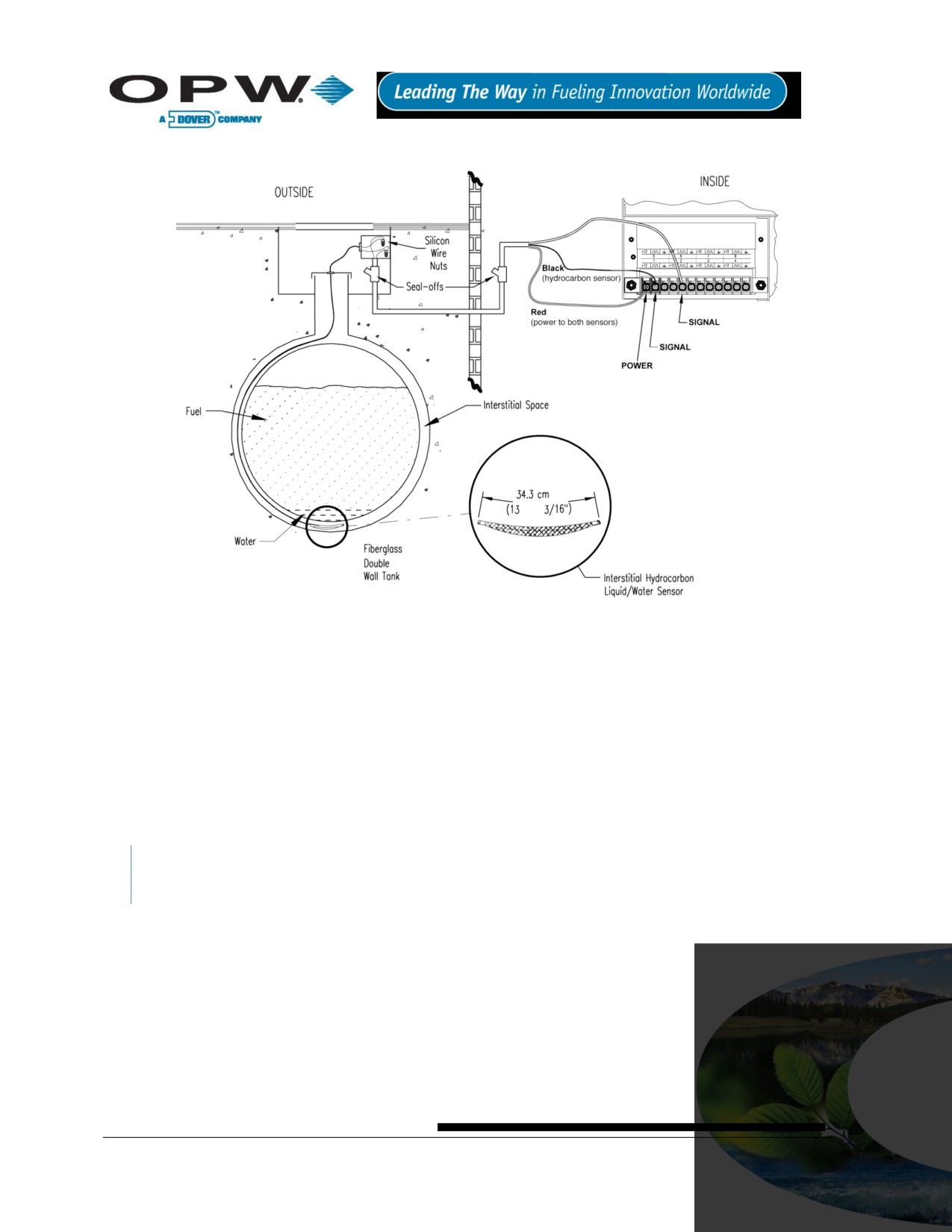
13.2.5 Typical Interstitial Hydrocarbon Liquid/Water Sensor Installation
Figure 13-2 Interstitial (IS) Hydrocarbon Liquid/Water Sensor Installation
13.2.6 SiteSentinel® iTouch™ Controller Setup for Interstitial (“IS”) Hydrocarbon
Liquid/Water Sensor
13.2.7 1st IS Module Position - Hydrocarbon Liquid
1. Configure the barrier position to be a generic sensor (or if using SiteConnect™ choose the appropriate
icon) and install that position.
2. Using the controller, take a dynamic reading of the hydrocarbon portion of the sensor.
3. Set the lower alarm threshold to be 0.5 volts lower than the reading taken (this assumes that there is
no current hydrocarbon contamination).
SiteConnect™ will ask to adjust the lower threshold automatically, to 0.1 V below the current voltage
reading. Answer YES.
4. Set the upper alarm threshold to 5.0 volts (disables upper threshold).
5. Program the alarms associated with the lower threshold that you wish to activate if the sensor detects
hydrocarbon liquid.
Page 40 of 123
13.2.8 2nd IS Module Position - Water
1. Configure the barrier position to be a generic sensor (or if using SiteConnect™ choose the appropriate
icon) and install that position.
Set the upper alarm threshold to 0.5 volts.
2. Set the lower alarm threshold 0 volts (disables lower threshold).
3. Program the alarms associated with the upper threshold that you wish to activate if the sensor detects
water.
13.2.9 Testing and Decontaminating the Interstitial Hydrocarbon Liquid/Water
Sensor
When working in the hazardous area use caution to avoid a hazardous situation.
When testing or decontaminating the sensor, work in a well-ventilated area with no hot surfaces or open
flames. If the SiteSentinel® iTouch™ Controller fails to detect alarm conditions simulated here, also check that
your controller thresholds are correct.
Testing the Hydrocarbon Liquid Sensor Portion. Immerse the polymer in mineral spirits for about
10 minutes. Remove the sensor and let it hang to air dry. After another 10 minutes any controller
alarms or events associated with the hydrocarbon sensor should trigger. Disconnect this portion of the
sensor from the controller - an alarm should result. Short across these controller positions - an alarm
should also occur. If the open lead and/or short lead test fail, check all wiring and junction boxes for
continuity.
Testing the Water Sensor Portion. Immerse just the end of the sensor in tap water. Controller alarms
or events associated with the water portion of the sensor should trigger. Short the water portion of the
sensor - an alarm should occur. If the short lead test fails, check all wiring and junction boxes for
continuity.
Cleaning the Hydrocarbon Sensor Portion. To clean hydrocarbon contamination from the sensor
from testing or actual use, immerse the contaminated portion in denatured alcohol for one hour. Then,
flush the sensor with water to remove any residue. Leave the sensor to “settle” for another hour. The
sensor should return to nearly its original resistance, but it may be necessary to readjust the
controller’s thresholds.
Page 41 of 123

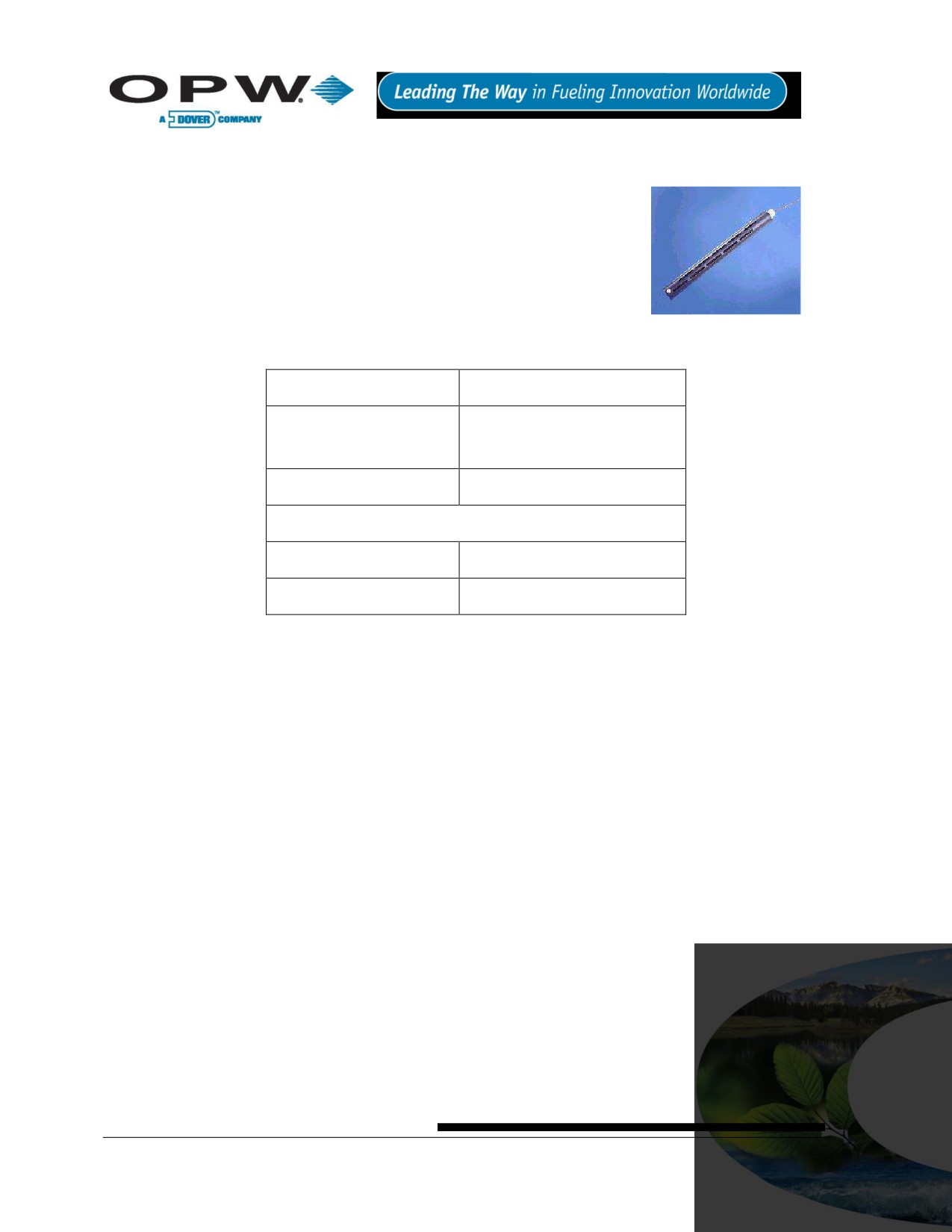
13.3 30-3207 Hydrocarbon Liquid Sensor
13.3.1 About the 30-3207-06, -10, -15
The hydrocarbon liquid sensors are used primarily in monitoring wells with
fluctuating groundwater tables. The hydrocarbon liquid sensor contains a
carbon/polymer material that changes its resistance when exposed to
liquid hydrocarbons.
Figure 13-3 Hydrocarbon Liquid
13.3.2 Specifications
Sensor
Operating Temperature
-20°C to 50°C (-4°F to 122°F)
Dimensions (depends on
1.8 cm (0.7 in) dia. x
part #)
1.8-4.6 m (6-15 ft)
Cable
3.1 m (10 ft) gas & oil-resistant cable
Nominal Resistance
Uncontaminated
1K - 3K ohms per foot
Contaminated
30K - 200K ohms
To ensure safe operating conditions the sensor has been designed to connect to OPW Fuel Management
Systems systems only.
13.3.3 Installing the 30-3207-06, -10, or -15
Hydrocarbons float on water
- if this sensor is fully submerged, the polymer will NOT detect
hydrocarbon liquid.
This sensor requires ONE Controller Interface Module position.
Review Figure 13-4 on page 43.
Use Table 13-2 below to connect the sensor to the Controller I.S. Interface Module terminals.
Use the supplied cable gland and silicone wire nuts.
Install seal-offs at both ends of the conduit run
13.3.4 Connections
Table 13-2 Hydrocarbon Liquid Sensor Wiring
I.S. Interface Module Position Terminal
Sensor Wire
+12
Red
Black
White - No connection
Page 42 of 123

13.3.5 Typical Hydrocarbon Liquid Sensor Installation
Figure 13-4 Hydrocarbon Liquid Sensor Installation
13.3.6 SiteSentinel® iTouch™ Controller Setup for Hydrocarbon Liquid Sensor
1. Configure the barrier position to be a generic sensor (or if using SiteConnect™ choose the
appropriate icon) and install that position.
2. Using the controller, take a dynamic reading of the hydrocarbon portion of the sensor.
3. Set the lower alarm threshold to be 0.5 volts lower than the reading taken (this assumes that there is
no current hydrocarbon contamination).
SiteConnect™ will ask to adjust the lower threshold automatically, to 0.1 V below the current voltage
reading. Answer YES.
4. Set the upper alarm threshold to be 5.0 volts (disables upper threshold).
5. Program the alarms associated with the lower threshold that you wish to activate if the sensor detects
hydrocarbon liquid.
13.3.7 Testing and Decontaminating the Hydrocarbon Liquid Sensor
When working in the hazardous area use caution to avoid a hazardous situation.
When testing or decontaminating the sensor, work in a well-ventilated area with no hot surfaces or open
flames.
If the SiteSentinel® iTouch™ Controller fails to detect alarm conditions simulated here, also check that your
controller thresholds are correct.
Page 43 of 123
Testing the Hydrocarbon Liquid Sensor. Immerse the polymer in mineral spirits for about 10
minutes. Remove the sensor and let it hang to air dry. After another 10 minutes any controller alarms
or events associated with the hydrocarbon sensor should trigger. Disconnect this portion of the sensor
from the controller - an immediate alarm should result. Short across these controller positions - an
alarm should also occur. If the open lead and/or short lead test fail, check all wiring and junction boxes
for continuity.
Cleaning the Hydrocarbon Liquid Sensor. To clean hydrocarbon contamination from the sensor
from testing or actual use, immerse the contaminated portion in denatured alcohol for one hour. Then,
flush the sensor with water to remove any residue. Leave the sensor to “settle” for another hour. The
sensor should return to nearly its original resistance, but it may be necessary to re-adjust the
controller’s thresholds.
13.4 30-3210-06, -10, -15 Hydrocarbon Liquid/Water Sensor
13.4.1 About the 30-3210-nn
The hydrocarbon liquid/water sensor is used primarily in monitoring wells with
fluctuating groundwater tables or in containment areas of tanks, pumps and
pipes.
The sensor contains a carbon/polymer material that changes its resistance
when exposed to liquid hydrocarbons, as well as a water sensor that relies on
the conductivity of water to detect its presence, providing the ability to
discriminate between hydrocarbon liquid and water.
Figure 13-5 Hydrocarbon
Liquid/Water Sensor
The sensor also alerts the system to the absence of groundwater in a
monitoring well or the presence of water in containment areas. It will alert the system if any fuel enters into the
containment area, which would indicate a leak. In the event of a break in the cable the system will activate the
alarm.
13.4.2 Specifications
Operating Temperature
-20°C to 50°C (-4°F to 122°F)
Dimensions (depends on part #)
1.8 cm (0.7 in) dia. x
1.8 - 4.5 m (6 - 20 ft)
Cable
3.1 m (10 ft) gas & oil-resistant
Nominal Polymer Resistance
Uncontaminated
1K - 3K ohms per foot
Contaminated
30K - 200K ohms
To ensure safe operating conditions the sensor has been designed to connect to OPW Fuel Management
Systems systems.
Page 44 of 123

13.4.3 Installing the 30-3210-06, -15, -20
This sensor requires TWO Controller Interface Module positions.
Review Figure 13-6 on page 46.
Use Table 13-3 below to connect the sensor to the Controller I.S. Module.
Use the supplied cable gland and silicone wire nuts.
Install seal-offs at both ends of the conduit run.
13.4.4 Connections
Table 13-3 Hydrocarbon Liquid/Water Sensor Wiring
I.S. Interface Module Position 1 Terminals
Sensor Wire
+12
Red
Black (hydrocarbon)
No Connection
I.S. Interface Module Position 2 Terminals
Sensor Wire
+12
No connection
White (water)
No Connection
Page 45 of 123

13.4.5 Typical Hydrocarbon Liquid/Water Sensor Installation
Figure 13-6 Hydrocarbon Liquid & Water Sensor Installation
13.4.6 SiteSentinel® iTouch™ Controller Setup for Hydrocarbon Liquid/Water
Sensor
13.4.7 Hydrocarbon Sensor Configuration
1. Configure the barrier position for the hydrocarbon sensor portion to be a generic sensor (or if using
SiteConnect™ choose the appropriate icon) and install that position.
2. With the controller, take a dynamic reading of the hydrocarbon portion of the sensor.
3. Set the lower alarm threshold to 0.5 volts lower than the reading you obtained in Step 2 (assumes no
current hydrocarbon contamination).
4. Set the upper threshold to 5.0 volts (disables upper threshold).
5. Program the alarms associated with the lower threshold that will activate in the presence of liquid
hydrocarbons.
SiteConnect™ will ask to adjust the lower threshold automatically, to 0.1 V below the current voltage
reading. Answer YES.
13.4.8 Water Sensor Configuration
1. Configure the barrier position for the water sensor portion to be a generic sensor (or if using
SiteConnect™ choose the appropriate icon) and install that position.
2. Set the upper alarm threshold to 0.5 volts. Set the lower alarm threshold to 0.0 volts (disables lower
threshold).
Page 46 of 123
13.4.9 Testing the Sensor
When working in the hazardous area use caution to avoid a hazardous situation. When testing or
decontaminating a hydrocarbon sensor, work in a well-ventilated area with no hot surfaces or open
flames.
Testing and Cleaning the Hydrocarbon Sensor. Immerse the polymer in mineral spirits for about 10
minutes. Remove the sensor and let it hang to air dry. After another 10 minutes any controller alarms
or events associated with the hydrocarbon sensor should trigger. Disconnect this portion of the sensor
from the controller - an immediate alarm should result. Short across these controller positions - an
alarm should also occur. If the open lead and/or short lead test fail, check all wiring and junction boxes
for continuity.
To clean hydrocarbon contamination from the sensor from testing or actual use, immerse the
contaminated portion in denatured alcohol for one hour. Then, flush the sensor with water to remove
any residue. Leave the sensor to “settle” for another hour. The sensor should return to nearly its
original resistance, but it may be necessary to re-adjust the controller’s thresholds.
Testing the Water Sensor. Immerse just the end of the sensor in tap water. Controller alarms or
events associated with the water portion of the sensor should trigger. Short the water portion of the
sensor - an alarm should occur. If the short lead test fails, check all wiring and junction boxes for
continuity.
Page 47 of 123
13.5 30-3219-12 Hydrocarbon Liquid Sump Sensor
13.5.1 About the 30-3219-12
The hydrocarbon liquid sump sensor is designed to detect the presence of
liquid hydrocarbons in sumps, dispenser pans and other locations where the
presence of a hydrocarbon liquid could indicate that a leak has occurred.
The hydrocarbon liquid sensor contains a carbon/polymer material that
changes its resistance when exposed to liquid hydrocarbons. In the event of a
break in the cable, the system will activate the alarm.
Figure 13-7 Hydrocarbon
Liquid Sump Sensor
13.5.2 Specifications
Operating Temperature
-20°C to 50°C (-4°F to 122°F)
Dimensions
4.4 cm (1.7 in) dia. x
33.5 cm (13.2 in) long
Cable
3.6 m (12 ft) gas & oil-resistant
Normal Resistance
Uncontaminated
1K - 5K ohms
Contaminated
30K - 200K ohms
To ensure safe operating conditions the sensor has been designed to connect to OPW Fuel Management
Systems systems only.
Page 48 of 123

13.5.3 Installing the 30-3219-12
Hydrocarbons float on water
- if this sensor is fully submerged, the polymer will NOT detect
hydrocarbon liquid.
This sensor requires ONE Controller Interface Module positions.
Review Figure 13-8 on page 50.
Use Table 13-4 below to connect the sensor to the Controller I.S. module.
Use the supplied cable gland and silicone wire nuts.
Install seal-offs at both ends of the conduit run.
13.5.4 Connections
Table 13-4 Hydrocarbon Liquid Sump Sensor Wiring
I.S. Interface Module Position
Sensor Wire
+12
Red
Black
No Connection
Page 49 of 123

13.5.5 Typical Hydrocarbon Liquid Sump Sensor Installation
Figure 13-8 Hydrocarbon Liquid Sump Sensor Installation
13.5.6 SiteSentinel® iTouch™ Controller Setup for Hydrocarbon Liquid Sump
Sensor
1. Configure the barrier position to be a generic sensor (or if using SiteConnect™ choose the
appropriate icon) and install that position.
2. Using the Controller, take a dynamic reading of the hydrocarbon portion of the sensor.
3. Set the lower alarm threshold to be 0.2 volts lower than the reading taken (this assumes that there is
no current hydrocarbon contamination).
SiteConnect™ will ask to adjust the lower threshold automatically, to 0.1 V below the current voltage
reading. Answer YES.
4. Set the upper alarm threshold to be 5.0 volts (disables upper threshold).
5. Program the alarms associated with the lower threshold that you wish to activate if the sensor detects
hydrocarbon liquid.
Page 50 of 123
13.5.7 Testing and Decontaminating the Hydrocarbon Liquid Sump Sensor
When working in the hazardous area use caution to avoid a hazardous situation.
When testing or decontaminating the sensor, work in a well-ventilated area with no hot surfaces or open
flames.
If the SiteSentinel® ITouch™ Controller fails to detect alarms conditions simulated here, also check that your
controller thresholds are correct.
Testing the Hydrocarbon Liquid Sump Sensor. Immerse the polymer in mineral spirits for about 10
minutes. Remove the sensor and let it hang to air dry. After another 10 minutes, any controller alarms
or events associated with the hydrocarbon sensor should trigger. Disconnect this portion of the sensor
from the controller - an immediate alarm should result. Short across these controller positions - an
alarm should also occur. If the open lead and/or short lead test fail, check all wiring and junction boxes
for continuity.
Cleaning the Hydrocarbon liquid Sump Sensor. To clean hydrocarbon contamination from the
sensor from testing or actual use, immerse the contaminated portion in denatured alcohol for one hour.
Then, flush the sensor with water to remove any residue. Leave the sensor to “settle” for another hour.
The sensor should return to nearly its original resistance, but it may be necessary to readjust the
controller’s thresholds.
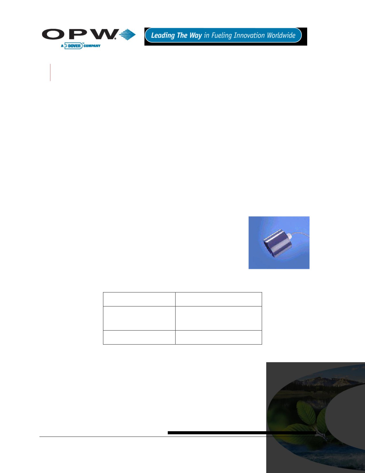
13.6 30-3221-1 Single-Level Sump Sensor
13.6.1 About the 30-3221-1
The single-level sump sensor is designed to detect the presence of liquid in
sumps, dispenser pans and other locations where the presence of a liquid
could indicate that a leak has occurred.
This sensor can also be used to monitor wet wells to ensure that liquid is
normally present. The sensor contains a float switch that activates in the
presence of liquid. In the event of a break in the cable, the system will activate
the alarm.
Figure 13-9 Single-Level Sump
Sensor
13.6.2 Specifications
Operating Temperature
-20°C to 50°C (-4°F to 122°F)
Dimensions
7.4 cm (2.9 in) dia x
9.5 cm (3.7 in) long
Cable
4.6 m (15 ft) gas & oil-resistant
To ensure safe operating conditions, the sensor has been designed to connect to OPW Fuel Management
Systems systems only.
Page 51 of 123

13.6.3 Installing the 30-3221-1
If monitoring a normally dry well, use a meter to orient the float so the sensor is in the closed state with
NO liquid present (float in lower position). If monitoring a normally wet well, use a meter to orient the
float so that it is in the closed state WITH liquid present (float in upper position).
This sensor requires ONE Interface Module position.
Review Figure 13-10 on page 53.
Use Table 13-5 below to connect the sensor to the Controller I.S. Interface Module terminals.
Use the supplied cable gland and silicone wire nuts.
Install seal-offs at both ends of the conduit run
13.6.4 Connections
Table 13-5 Single-Level Sump Sensor Wiring
I.S. Interface Module Position
Sensor Wire
+12
Red
Black
No Connection
Page 52 of 123

13.6.5 Typical Single-Level Sump Sensor Installation
Figure 13-10 Single-Level Sump Sensor Installation
13.6.6 SiteSentinel® iTouch™ Controller Setup for Single-Level Sump Sensor
1. Configure the barrier position to be a generic sensor (of if using SiteConnect™ choose the appropriate
icon) and install that position.
2. Set the lower alarm threshold to 2.5 volts set the upper alarm threshold to 5.0 volts (disables upper
threshold).
3. Program the alarms associated with the lower threshold to the lower threshold that you wish to activate
if the sensor detects hydrocarbon liquid.
13.6.7 Testing the Single-Level Sump Sensor Float
When working in the hazardous area use caution to avoid a hazardous situation.
When testing the senor, work in a well-ventilated area with no hot surfaces or open flames.
If Sensor Installed in a Normally DRY Well
Place the float in the UPPER position - this should trigger an alarm in the controller.
Return the float to the LOWER position - the alarm should end.
If Sensor Installed in a Normally WET Well
Place the float in the LOWER position - this should trigger an alarm in the controller
Return the float to the UPPER position - the alarm should end.
If the controller fails to register the alarm conditions, check your programmed thresholds in the controller.
Check the orientation of the float as described on page 58. Disconnecting the sensor should trigger an alarm
and shorting the sensor should be out of alarm. Check all wiring and junction boxes to ensuring continuity
without shorts.
Page 53 of 123

13.7 30-3221-2 Dual-Level Reservoir Sensor
13.7.1 About 30-3221-2
The dual-level reservoir sensor is designed for use in the brine-filled reservoir of
the interstitial area of a double-walled tank. This sensor contains a dual-level
float switch that detects level changes of fluid in the reservoir of the tank. The
sensor expects the liquid to be at a constant level. The system will activate the
alarm when the brine level in the interstitial space either rises or falls.
It can also be used in other areas (such as dispenser containment pans) that
are normally dry and will give a low-level warning followed by a high-level alarm.
Figure 13-11 Dual-Level
In the event of a break in the cable, the system will activate the alarm.
Reservoir Sensor
13.7.2 Specifications
Operating Temperatures
-20°C to 50°C (-4°F to 122°F)
Dimensions
6 cm (2.4 in) dia. x
35.6 cm (14 in) long
Cable
4.5 m (15 ft) gas & oil-resistant
To ensure safe operating conditions the sensor has been designed to connect to OPW Fuel Management
Systems systems only.
Page 54 of 123

13.7.3 Installing the 30-3221-2
The logic for this sensor can be changed by simply flipping the lower float. To remove the lower float,
use needle-nose pliers to remove the bottom clip. Then, remove the plastic cover and the float clip,
followed by the float itself.
If you are monitoring a normally wet well (brine-filled reservoir), orient the float with the CLOSED arrow pointing
downward.
If you are monitoring a normally dry well, make sure to orient the float with the CLOSED arrow pointing upward.
This sensor requires ONE Interface Module position.
Review Figure 13-12 on page 56.
Use Table 13-6 below to connect the sensor to the Controller I.S. Interface Module terminals.
Use the supplied cable gland and silicone wire nuts.
Install seal-offs at both ends of the conduit run
13.7.4 Connections
Table 13-6 Dual-Level Reservoir Sensor Connections
I.S. Interface Module Position Terminal
Sensor Wire
+12
Red
White
No connection
Page 55 of 123

13.7.5 Typical Dual-Level Reservoir Sensor Installation
Figure 13-12 Dual-Level Sump Sensor Installation
13.7.6 SiteSentinel® iTouch™ Controller Setup for Dual-Level Reservoir Sensor
1. Configure the barrier position to be a generic sensor (or if using SiteConnect™, choose the
appropriate icon) and install that position.
2. Set the lower alarm threshold to 2.2 volts. Set the upper alarm threshold to 3.4 volts.
If monitoring a normally wet well, the 3.4 volt threshold means liquid is too low. The 2.2 volt
threshold means liquid is too high.
If monitoring a normally dry well, the 3.4 volt threshold is where liquid is above the lower
float. The 2.2 volt threshold is where liquid is above the upper float.
3. Program the alarms associated with the thresholds you wish to activate if the sensor detects liquid.
Page 56 of 123
13.7.7 Testing the Dual-Level Reservoir Sensor Float
When working in the hazardous area use caution to avoid a hazardous situation.
When testing the sensor, work in a well-ventilated area with no hot surfaces or open flames.
If Sensor Installed in a Normally DRY Well
Place the LOWER float in its UPPER position and the UPPER float in its LOWER position. This should
trigger a low-level alarm in the controller.
Place the LOWER float in its UPPER position and the UPPER float in its UPPER position. This should
trigger a high-level alarm in the controller.
Return BOTH floats to their LOWER positions and check that the controller is no longer in the alarm
state.
If Sensor Installed in a Normally WET Well
Place the LOWER float in its LOWER position and the UPPER float in its LOWER position. This should
trigger a low-level alarm in the controller.
Place the LOWER float in its UPPER position and the UPPER float in its UPPER position. This should
trigger a high-level alarm in the controller.
Place the LOWER float in its UPPER position and the UPPER float in its LOWER position. Confirm
that the controller is no longer in an alarm state.
If the controller fails to register the alarm condition, check your programmed thresholds in the controller.
Check the orientation of the lower float as described on page 54.
Disconnecting the sensor should trigger a high-level alarm. Shorting the sensor should generate a low-level
alarm. Check all wiring and junction boxes to ensure continuity without shorts.
Page 57 of 123

13.8 30-3221-1A, -1B Interstitial Level Sensors
13.8.1 About the 30-3221-1A, 1B
The two types of interstitial level sensor are used primarily in the interstitial
area of a double-walled tank. The sensor contains a float switch that
activates in the presence of a liquid. The 30-3221-1A is constructed from a
chemical-resistant non-metallic material and the B30-3221-1B is
constructed from brass.
It can also be used in sumps, dispenser pans and other locations where
the presence of a liquid could indicate that a leak has occurred. In
combination with a vapor sensor, this sensor can be used to monitor wet
wells to ensure that a liquid is normally present. In the event of a break in
Figure 13-13 Part # 30-3221-1B
the cable the system will activate the alarm.
13.8.2 Specifications
To ensure safe operating conditions, the sensor has been designed to
connect to OPW Fuel Management Systems only.
Figure 13-14 Part # 30-3221-1A
Operating Temperature
-20°C to 50°C (-4°F to 122°F)
Dimensions 30-3221-1A
3.4 cm (1.3 in) dia x
10 cm (3.9 in) long
Dimensions 30-3221-1B
3.5 cm (1.4 in) dia x
9.0 cm (3.5 in) long
Cable
4.5 m (15 ft) gas & oil-resistant
Page 58 of 123

13.8.3 Installing the 30-3221-1A, -1B
If monitoring a normally dry well, use a meter to orient the float so the sensor is in the closed state with
NO liquid present (float in lower position). If monitoring a normally wet well, use a meter to orient the
float so that it is in the closed state WITH liquid present (float in upper position).
This sensor requires ONE Interface Module position.
Review Figure 13-15 on page 60.
Use Table 13-7 below to connect the sensor to the Controller I.S. Interface Module terminals.
Use the supplied cable gland and silicone wire nuts.
Install seal-offs at both ends of the conduit run.
13.8.4 Connections
Table 13-7 Interstitial Level Sensor Wiring
I.S. Interface Module Position
Sensor Wire
+12
Red
Black
No Connection
Page 59 of 123
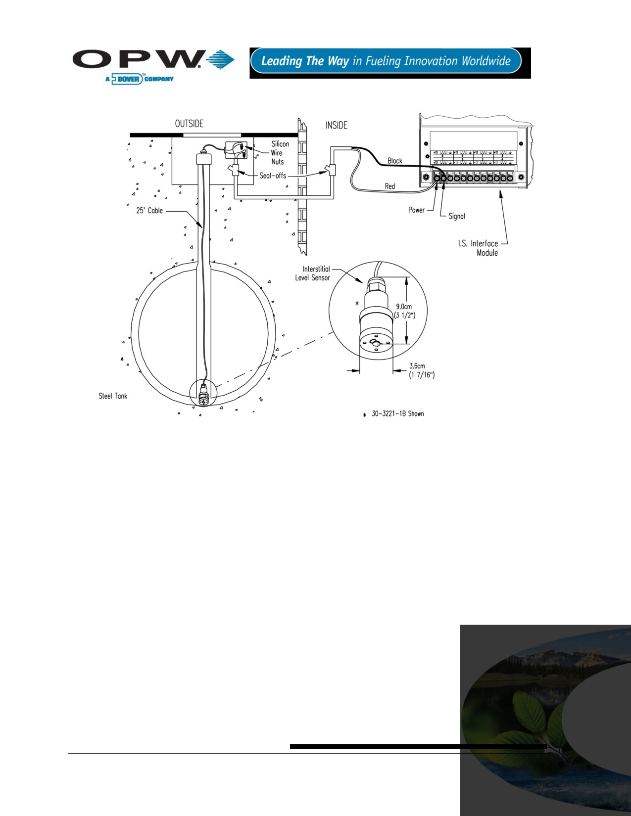
13.8.5 Typical Interstitial Level Sensor Installation
Figure 13-15 Interstitial Level Sensor Installation
13.8.6 SiteSentinel® iTouch™ Controller Setup for Interstitial Level Sensor
1. Configure the barrier position to be a generic sensor (or if using SiteConnect™, choose the
appropriate icon) and install that position.
2. Set the lower alarm threshold to 2.5 volts and set the upper alarm threshold to 5.0 volts (disables
upper threshold).
If monitoring a normally wet well, the lower threshold will indicate that the liquid is too low.
If monitoring a normally dry well, the lower threshold indicates that liquid is too high.
3. Program the alarms associated with the lower threshold that you wish to activate if the sensor detects
hydrocarbon liquid.
Page 60 of 123
13.8.7 Testing the Float Sensor
When working in the hazardous area use caution to avoid a hazardous situation.
When testing the sensor, work in a well-ventilated area with no hot surfaces or open flames.
If Sensor Installed in a Normally DRY Well
Place the float in the UPPER position - this should trigger an alarm in the controller.
Return the float to the LOWER position - the alarm should end.
If Sensor Installed in a Normally WET Well
Place the float in the LOWER position - this should trigger an alarm in the controller.
Return the float to the UPPER position - the alarm should end.
If the controller fails to register the alarm condition, check your programmed thresholds in the controller. Check
the orientation of the float as described on page 59. Disconnecting the sensor should trigger an alarm and
shorting the sensor should be out of alarm. Check all wiring and junction boxes to ensuring continuity without
shorts.
Page 61 of 123
13.9 30-3222 Hydrocarbon Vapor Sensor
13.9.1 About Part #30-3222
The hydrocarbon vapor sensor is designed to detect hydrocarbon vapors in
monitoring wells and the interstitial areas of a double-walled tank. The presence
of these vapors could indicate a potentially dangerous leak that could lead to
safety and environmental problems.
The sensor is made from a long-life resistive element that increases dramatically
in resistance in the presence of hydrocarbon vapors. After the vapors have
Figure 13-16 Hydrocarbon
dissipated, the sensor returns to normal and is ready to detect hydrocarbon
Vapor Sensor
vapors again. In the event of a break in the cable, the system will activate the
alarm.
13.9.2 Specifications
Operating Temperature
-20°C to 50°C (-4°F to 122°F)
Dimensions
2.3 cm (0.9 in) dia x
8.9 cm (3.5 in) long
Cable
4.5 m (12 ft) gas & oil-resistant
Nominal Resistance
Uncontaminated
3K - 5K ohms
Contaminated
10K - 200K ohms
To ensure safe operating conditions the sensor has been designed to connect to OPW Fuel Management
Systems systems only.
Page 62 of 123

13.9.3 Installing the 30-3222
When installing, avoid any immersion in liquid (either hydrocarbon or water). Immersion shortens the
sensor’s life. Immersion may also prevent the sensor from working properly.
The sensor requires ONE Interface Module position.
Review Figure 13-17 on page 64.
Use Table 13-8 below to connect the sensor to the Controller I.S. Interface Module terminals.
Use the supplied cable gland and silicone wire nuts.
Install seal-offs at both ends of the conduit run
13.9.4 Connections
Table 13-8 Hydrocarbon Vapor Sensor Wiring
I.S. Interface Module Position
Sensor Wire
+12
Red
Black
No Connection
Page 63 of 123
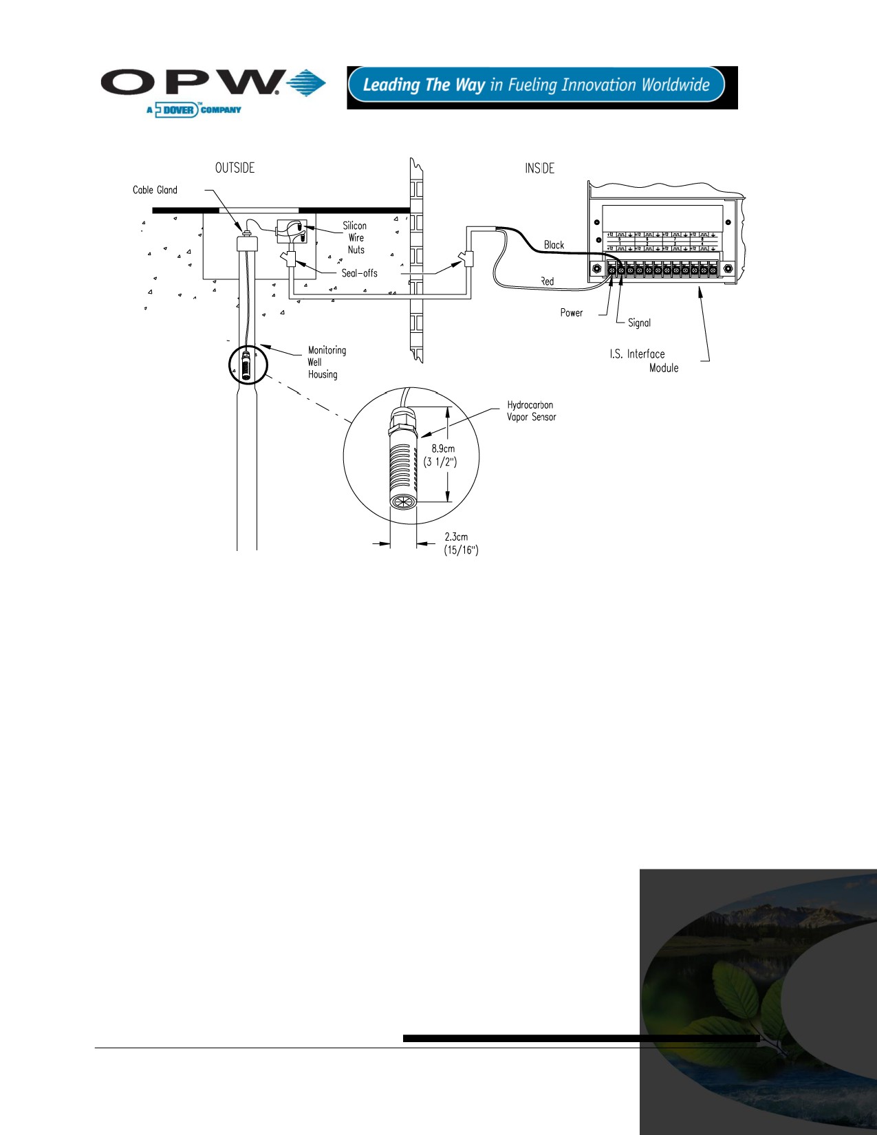
13.9.5 Typical Hydrocarbon Vapor Sensor Installation
Figure 13-17 Hydrocarbon Vapor Sensor Installation
13.9.6 SiteSentinel® iTouch™ Controller Setup for Hydrocarbon Vapor Sensor
1. Configure the barrier position to be a generic sensor (or if using SiteConnect™ choose the
appropriate icon) and install that position.
2. Using the controller take a dynamic reading of the hydrocarbon portion of the sensor.
3. Set the lower alarm threshold to be 0.1 volts lower than the reading taken (this assumes that there is
no current hydrocarbon contamination)
4. Set the upper alarm threshold to be 5.0 volts (disables upper threshold).
5. Program your alarms to activate if the sensor detects hydrocarbons.
Page 64 of 123
13.9.7 Testing and Decontaminating the Hydrocarbon Vapor Sensor
To test the hydrocarbon vapor sensor:
1. Pour some mineral spirits into an empty can or other container.
2. Suspend the hydrocarbon sensor inside the container, in the air above the mineral spirits.
3. Wait approximately 10 minutes. After 10 minutes, any controller alarms or events associated with the
sensor should have triggered.
To clean the sensor from hydrocarbon contamination (or after testing):
1. Immerse the sensor in denatured alcohol.
2. Let the sensor soak for one hour.
3. Remove the sensor from the alcohol and let stand for one hour before using.
The sensor should have returned to nearly its original resistance, but it may be necessary to re-adjust the
controller’s thresholds. If the controller fails to register the alarm condition, check your programmed thresholds
in the controller. Disconnecting the sensor should trigger an alarm and shorting the sensor should be out of
alarm. Check all wiring and junction boxes to ensuring continuity without shorts.
Page 65 of 123

13.10 30-3223 Interstitial Optical Liquid Sensor
13.10.1
About the 30-3223
The interstitial optical liquid sensor is used primarily to monitor the interstitial
area of double-walled tanks. This sensor incorporates a long-life optical prism
and can also be used in sumps, dispenser pans and other locations where the
presence of a liquid could indicate that a leak has occurred.
The sensor does NOT differentiate water and hydrocarbon liquid. In the event
of a break in the cable, the system will activate the alarm.
Figure 13-18 Interstitial Optical
13.10.2
Specifications
Liquid Sensor
Operating Temperature
-20°C to 50°C (-4°F to 122°F)
Dimensions
1.8 cm (0.7 in) dia. x
7.0 cm (2.8 in) long
Cable
6.1 m (20 ft) gas & oil resistant
To ensure safe operating conditions the sensor has been designed to connect to OPW Fuel Management
Systems systems only.
13.10.3
Installing the 30-3223
This sensor requires ONE Interface Module position.
Review Figure 13-19 on page 67.
Use Table 13-9 below to connect the sensor to the Controller I.S. Interface Module terminals.
Use the supplied cable gland and silicone wire nuts.
Install seal-offs at both ends of the conduit run.
13.10.4
Connections
Table 13-9 Interstitial Optical Liquid Sensor Wiring
I.S. Interface Module Position
Sensor Wire
+12
Red
White
Black
Page 66 of 123
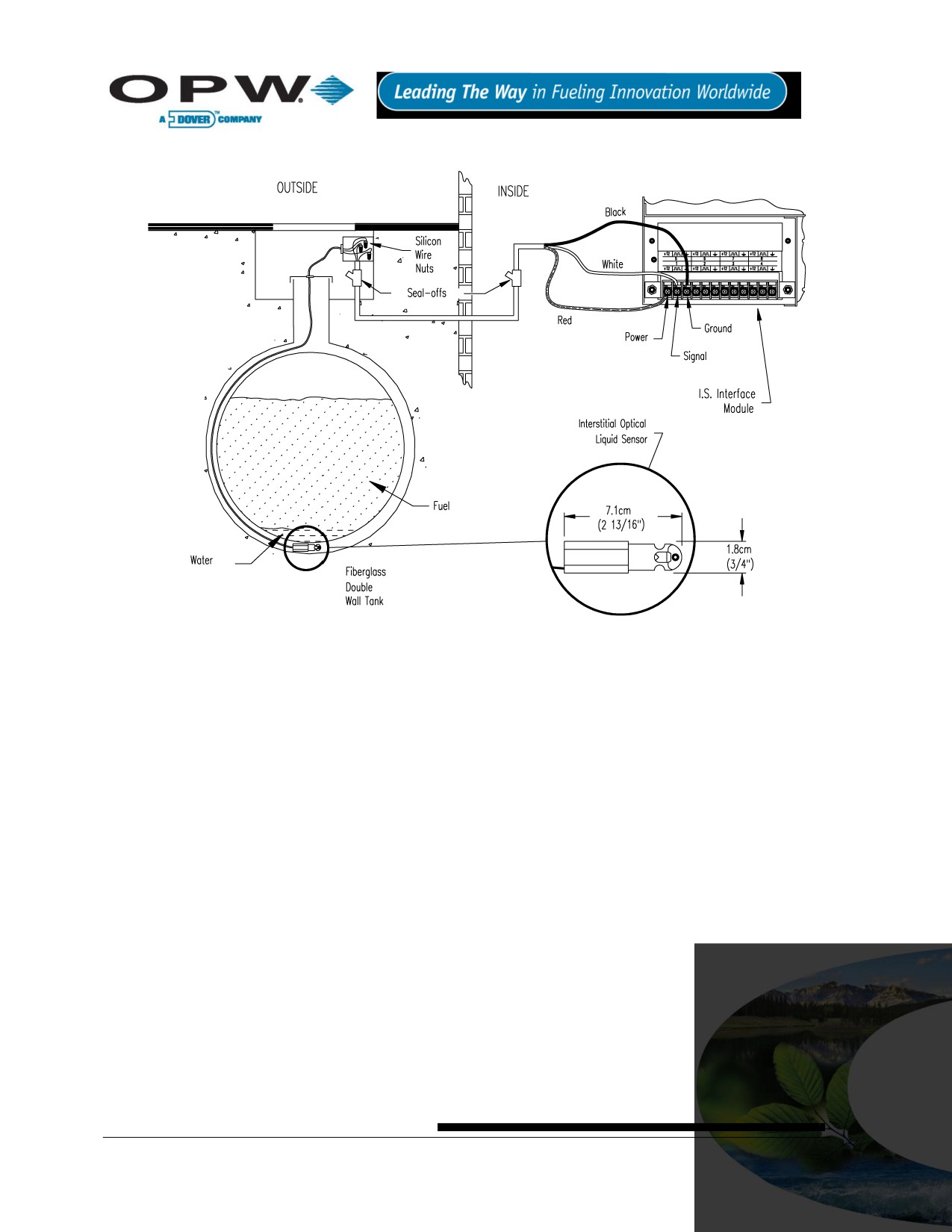
13.10.5
Typical Interstitial Optical Liquid Sensor Installation
Figure 13-19 Interstitial Optical Liquid Sensor Installation
13.10.6
Controller Setup for Interstitial Optical Liquid Sensor
1. Configure the barrier position to be a generic sensor (or if using SiteConnect™ choose the
appropriate icon) and install that position.
2. Set the lower alarm threshold to 0.2 volts and set the upper alarm threshold to 5.0 volts (disables
upper threshold).
3. Program the alarms associated with the lower threshold that you wish to activate if the sensor detects
liquid.
13.10.7
Testing the Interstitial Optical Liquid Sensor
1. Immerse the sensor in water. This should trigger the alarm in the controller.
2. Remove the sensor from the water. Confirm that the controller is no longer in alarm.
If the controller fails to go in to alarm condition, check that the thresholds programmed in the system are
correct. Disconnecting the sensor should trigger an alarm. Shorting the sensor should be out of alarm. Check
all wiring and junction boxes to ensure continuity without shorts.
Page 67 of 123
13.11 30-3224 Combo Single Level/Hydrocarbon Liquid Sump Sensor
13.11.1
About the 30-3224
This combination sensor is made from a Hydrocarbon Liquid Sump Sensor
(page 48) with an Interstitial Level Sensor (page 58) clipped to the side.
The sensor is designed to detect the presence of liquid hydrocarbons and
water in sumps, dispenser pans and other locations where the presence of
a
liquid could indicate that a leak has occurred.
The sensor contains a carbon/polymer material that changes its resistance
when exposed to liquid hydrocarbons. A float switch simply clips onto the
Figure 13-20 Combo Single
hydrocarbon sensor and can be positioned at any desired height to activate in
Level/Hydrocarbon liquid
the presence of liquid
Sump Sensor
This sensor can be used to monitor wet wells to ensure that a liquid is normally present. In the event of a break
in the cable, the system will activate the alarm.
13.11.2
Specifications
Operating Temperature
-20°C to 50°C (-4°F to 122°F)
Dimensions
30-3221-1A
3.4 cm (1.3 in) dia x
10 cm (3.9 in) long
30-3221-12
4.4 cm (1.7 in) dia x
33.5 cm (13.2 in) long
Nominal Resistance
Uncontaminated
1K - 5K ohms
Contaminated
30K - 200K ohms
Cable
3.6 m (12 ft) gas & oil-resistant
To ensure safe operating conditions the sensor has been designed to connect to OPW Fuel Management
Systems systems only.
Page 68 of 123

13.11.3
Installing the 30-3224
If monitoring a normally dry well, use a meter to orient the Single-Level Float portion of the sensor so the
sensor is in the closed state with NO liquid present (float in lower position). If monitoring a normally wet
well orient the float so that it is in the closed state WITH liquid present (float in upper position).
This sensor requires TWO Interface Module positions.
Review Figure 13-21 on page 70.
Use Table 13-10 below to connect the sensor to the Controller I.S. Interface Module terminals.
Use the supplied cable gland and silicone wire nuts.
Install seal-offs at both ends of the conduit run.
13.11.4
Connections
Only three (3) wires are required to connect the sensor to the controller positions. Use one wire as the
common power connection to each sensor (red wires). The other two wires bring each sensor’s data
back to the separate controller data terminal.
Table 13-10 Combo Single-Level/Hydrocarbon Sensor Wiring
I.S. Interface Module Position 1 Terminal
Sensor Wire
+12
Red (joined 30-3219-12 and 30-3221-1A red
leads, in junction box).
Black (from Hydrocarbon Sensor)
No Connection
I.S. Interface Module Position 2 Terminal
Sensor Wire
+12
No Connection
White (from Liquid Level Sensor)
No Connection
Page 69 of 123
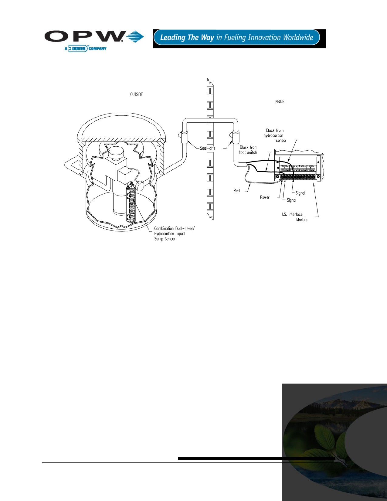
13.11.5
Typical Combo Single-Level/Hydrocarbon Liquid Sump Sensor
Installation
Figure 13-21 Combo Single-Level & Hydrocarbon Liquid Sensor Installation
13.11.6
Controller Setup for Combo Single-Level/Hydrocarbon Sump Sensor
1st Barrier Position (Float Sensor)
1. Configure the barrier position to be a sensor (or if using SiteConnect™ chose the appropriate icon)
and install that position.
2. Set the lower alarm threshold to 2.5 volts.
3. Set the upper alarm threshold to 5.0 volts (disables upper threshold).
If monitoring a normally wet well, the lower threshold will indicate that the liquid is too low.
If monitoring a normally dry well, the lower threshold indicates that liquid is too high.
4. Program the alarms associated with the lower threshold that you wish to activate if the sensor detects
hydrocarbon liquid.
2nd Barrier Position (Hydrocarbon Sensor)
1. Configure the barrier position to be a sensor (or if using SiteConnect™ choose the appropriate icon)
and install that position
2. Using the controller, take a dynamic reading of the hydrocarbon portion of the senor.
3. Set the lower alarm threshold to 0.2 volts lower than the reading taken (this assumes that there is no
current hydrocarbon contamination).
4. Set the upper alarm threshold to 5.0 volts (disables upper threshold).
5. Program the alarms associated with the lower threshold that you wish to activate if the sensor detects
hydrocarbon liquid.
Page 70 of 123
13.11.7
Testing the Float Sensor Portion of the Combo Sensor
Sensor installed in a normally DRY well
Place the float in the UPPER position. This should trigger an alarm in the controller.
Return the float to its lower position. Confirm that the alarm ends in the controller.
Sensor installed in a normally WET well
Place the float in the LOWER position. This should trigger an alarm in the controller.
Return the float to the upper position and check that the controller is no longer in alarm.
If the Controller fails to register the alarm condition, check your programmed thresholds in the controller.
Check the orientation of the float as described on page 69.
Disconnecting the sensor should trigger an alarm and shorting the sensor should be out of alarm. Check all
wiring and junction boxes to ensure continuity without shorts.
13.11.8
Testing and Decontaminating the Hydrocarbon Sensor Portion of the
Combo Sensor
When working in the hazardous area use caution to avoid a hazardous situation. When testing or
decontaminating the sensor, work in a well-ventilated area with no hot surfaces or open flames.
If the SiteSentinel® iTouch™ Controller fails to detect alarm conditions simulated here, also check that your
controller thresholds are correct.
Testing the Hydrocarbon Liquid Sump Sensor. Immerse the polymer in mineral spirits for about 10
minutes. Remove the sensor and let it hang to air dry. After another 10 minutes any controller alarms
or events associated with the hydrocarbon sensor should trigger. Disconnect this portion of the sensor
from the controller - an immediate alarm should result. Short across these controller positions - an
alarm should also occur. If the open lead and/or short lead test fail, check all wiring and junction boxes
for continuity.
Cleaning the Hydrocarbon Liquid Sump Sensor. To clean hydrocarbon contamination from the
sensor from testing or actual use, immerse the contaminated portion in denatured alcohol for one hour.
Then, flush the sensor with water to remove any residue. Leave the sensor to “settle” for another hour.
The sensor should return to nearly its original resistance, but it may be necessary to re-adjust the
controller’s thresholds.
Page 71 of 123
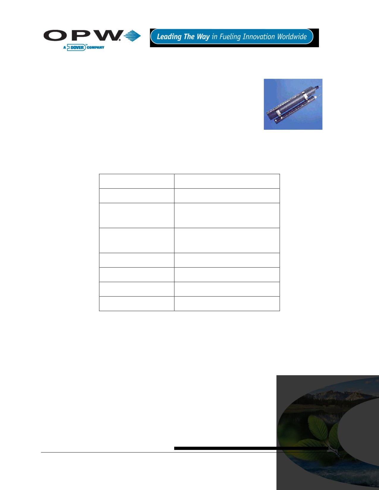
13.12 30-3225 Combo Dual Level/Hydrocarbon Liquid Sump Sensor
13.12.1
About the 30-3225
This sensor is made from the hydrocarbon liquid sump sensor (30-3219-12) and
from the dual level reservoir sensor (30-3221-2) clipped to the side. The
combination sump sensor is designed to detect the presence of liquid
hydrocarbons and water in sumps, dispenser pans and other locations where
the presence of a liquid could indicate that a leak has occurred.
The sensor contains a carbon/polymer material that changes its resistance
when exposed to liquid hydrocarbons. The dual float switch simply clips onto the
hydrocarbon sensor and can activate in the presence or absence of liquid. This
Figure 13-22 Combo Dual
Level/Hydrocarbon Liquid
sensor can be used to monitor wet wells to ensure that liquid is normally
Sump Sensor
present. In the event of a break in the cable, the system will activate the alarm.
13.12.2
Specifications
Operating Temperature
-20°C to 50°C (-4°F to 122°F)
Dimensions
30-3221-2
6 cm (2.4 in) dia x
35.6 cm (14 in) long
30-3219-12
4.4 cm (1.7 in) dia x
33.5 cm (13.2 in) long
Nominal Resistance
Uncontaminated
1K - 5K ohms
Contaminated
30K - 200K ohms
Cable
3.6 m (12 ft) gas & oil-resistant cable
To ensure safe operating conditions the sensor has been designed to connect to OPW Fuel Management
Systems systems only.
Page 72 of 123

13.12.3
Installing the 30-3225
Hydrocarbons float on water
- if this sensor is fully submerged, the polymer will NOT detect
hydrocarbon liquid.
This sensor requires TWO Controller Interface Module positions.
Review Figure 13-23 on page 74.
Use Table 13-11 below to connect the sensor to the Controller I.S. Interface Module Terminals.
Use the supplied cable gland and silicone wire nuts.
Install seal-offs at both ends of the conduit run.
For normally dry wells, use a meter to orient the Dual-Level Float portion of the sensor so the sensor is
in the closed state with NO liquid present (float in lower position). For a normally wet well, orient the float
so that it is in the closed state WITH liquid present (float in upper position).
13.12.4
Combo Sensor Connections
Table 13-11 Combo Dual-Level/Hydrocarbon Liquid Sump Sensor
I.S. Interface Module Position 1 Terminal
Sensor Wire
+12
Red (joined 30-3219-12 and 30-3221-2 red
leads, in junction box).
Black (from Hydrocarbon Sensor)
No Connection
I.S. Interface Module Position 2 Terminal
Sensor Wire
+12
No Connection
White (from Dual Liquid Level Sensor)
No Connection
Only three (3) wires are required to connect the sensor to the controller positions. Use one wire as the
common power connection to each sensor (red wires). The other two wires bring each sensor’s data
back to the separate controller data terminals.
Page 73 of 123

13.12.5
Typical Dual-Level Hydrocarbon Liquid Sump Sensor Installation
Figure 13-23 Combo Dual-Level & Hydrocarbon Liquid Sensor Installation
13.12.6
Controller Setup for 30-3225
1st Barrier Position (Dual Float Sensor)
1. Configure the barrier position to be a generic sensor (or if using SiteConnect™ choose the
appropriate icon) and install that position.
2. Set the lower alarm threshold to 2.2 volts and set the upper alarm threshold to 3.4 volts
If monitoring a normally wet well, the 3.4-volt threshold will indicate that the liquid is too low,
and the 2.2-volt threshold will indicate that the liquid is too high.
If monitoring a normally dry well, the 3.4-volt threshold indicates that liquid is above the lower
float, and the 2.2 volt threshold indicates that liquid is above the upper float.
3. Use SiteConnect™ to program all alarms associated with the appropriate thresholds to activate if the
sensor detects liquid.
2nd Barrier Position (Hydrocarbon Sensor)
1. Configure the barrier position to be a generic sensor (or if using SiteConnect™ choose the
appropriate icon) and install that position.
2. Using the controller, take a dynamic reading of the hydrocarbon portion of the sensor.
3. Set the lower alarm threshold to 0.2 volts lower than the reading taken (this assumes that there is no
current hydrocarbon contamination).
4. Set the upper alarm threshold to 5.0 volts (disables upper threshold).
5. Use SiteConnect™ to program all alarms associated with the lower threshold to activate if the sensor
detects hydrocarbon liquid.
Page 74 of 123
13.12.7
Testing the Float Sensor Portion of the Combo Sensor
Sensor Installed in a Normally Dry Well
1. Place the LOWER float in the UPPER position. Place the UPPER float in the LOWER position. This
should trigger an alarm in the controller.
2. Place both the LOWER and UPPER floats in the UPPER position. This should trigger a “High-Level”
alarm in the controller.
3. Return both floats to the LOWER position. Confirm that the alarm ends in the controller.
Sensor Installed in a Normally WET Well
1. Place the LOWER float in the LOWER position. Place the UPPER float in the LOWER position. This
should trigger an alarm in the controller.
2. Place the LOWER float in the UPPER position and move the UPPER float in the UPPER position. This
should trigger an alarm in the controller.
3. Leave the LOWER float in the UPPER position and move the UPPER float to the LOWER position.
Confirm that the controller is no longer in alarm.
If the controller fails to register the alarm condition, check your programmed thresholds in the controller.
Check the orientation of the floats as described on page 73.
Disconnecting the sensor should trigger an alarm and shorting the sensor should defeat an alarm. Check all
wiring and junction boxes to ensuring continuity without shorts.
13.12.8
Testing and Decontaminating the Hydrocarbon Portion of the Combo
Sensor
When working in the hazardous area use caution to avoid a hazardous situation.
When testing or decontaminating the sensor, work in a well-ventilated area with no hot surfaces or open
flames.
If the SiteSentinel® iTouch™ Controller fails to detect alarm conditions simulated here, also check that your
controller thresholds are correct.
Testing the Hydrocarbon Liquid Sump Sensor. Immerse the polymer in mineral spirits for about 10
minutes. Remove the sensor and let it hang to air dry. After another 10 minutes any controller alarms
or events associated with the hydrocarbon sensor should trigger. Disconnect this portion of the sensor
from the controller - an immediate alarm should result. Short across these controller positions - an
alarm should also occur. If the open lead and/or short lead test fail, check all wiring and junction boxes
for continuity.
Cleaning the Hydrocarbon Liquid Sump Sensor. To clean the hydrocarbon contamination from the
sensor from testing or actual use, immerse the contaminated portion in denatured alcohol for one hour.
Then, flush the sensor with water to remove any residue. Leave the sensor to “settle” for another hour.
The sensor should return to nearly its original resistance, but it may be necessary to re-adjust the
controller’s thresholds.
13.12.9
Testing the Water Sensor Portion of the Combo Sensor
Immerse only the water-detecting end of the sensor in tap water. Controller alarms or events associated with
the water portion of the sensor should immediately trigger.
Short the water portion of the sensor - an alarm should occur. If the short lead test fails, check all wiring and
junction boxes for continuity.
Page 75 of 123
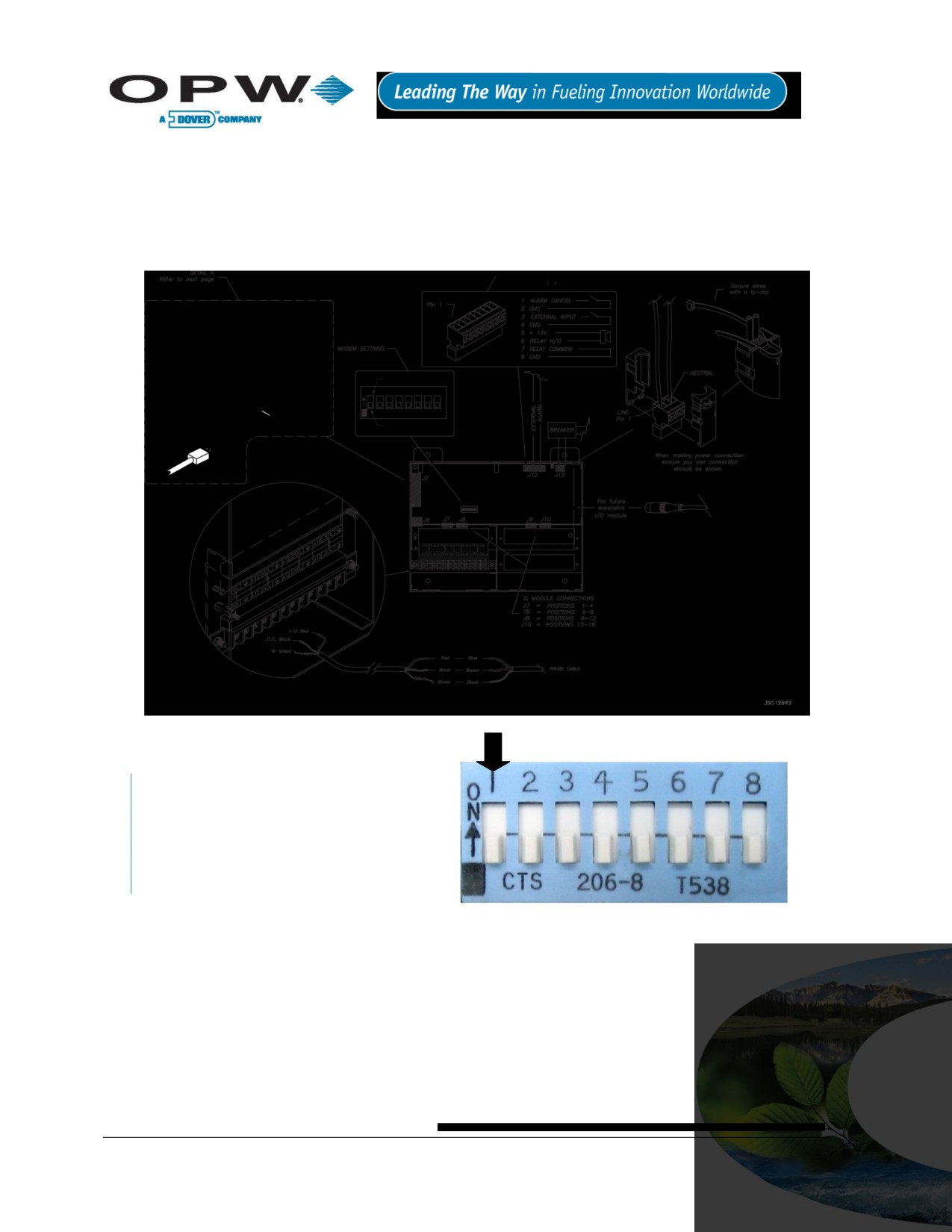
14 External Device Connection
Figure 14-1 below shows how to connect all possible devices and accessories to your SiteSentinel® iTouch™
Controller. Not all applications use all connections shown in the drawing.
Certain areas of the drawing are expanded in Figure 14-2 below, Figure 15-1 on page 77 and Figure 16-1 on
page 78. The modem settings are detailed on page 80.
Figure 14-1 Connecting External Devices to the Controller
Dip Switch 1 is used for internal selection
ONLY. Use the “On” position to select
external modem; the “off” is for internal
modem. Once the dip switch is changed,
the SiteSentinel® iTouch™ controller needs
to be restarted.
Figure 14-2 Dip Switch for Modem Settings
Page 76 of 123
15 RJ-45 Communication Ports
The SiteSentinel® iTouch™ Controller has five (5) RJ-45 ports as shown in Figure 15-1 below. From top to
bottom, they are for:
POS (Point-of-Sale) Device (see Appendix C - POS Interface on page 85)
Printer
CAP port: configuration port for SiteConnect™
TCP/IP (Internet - setting up a TCP/IP Interface on page 81)
External Modem (optional)
Internal Modem (standard)
Figure 15-1 SiteSentinel® iTouch™ RJ-45 Communication Ports
Page 77 of 123
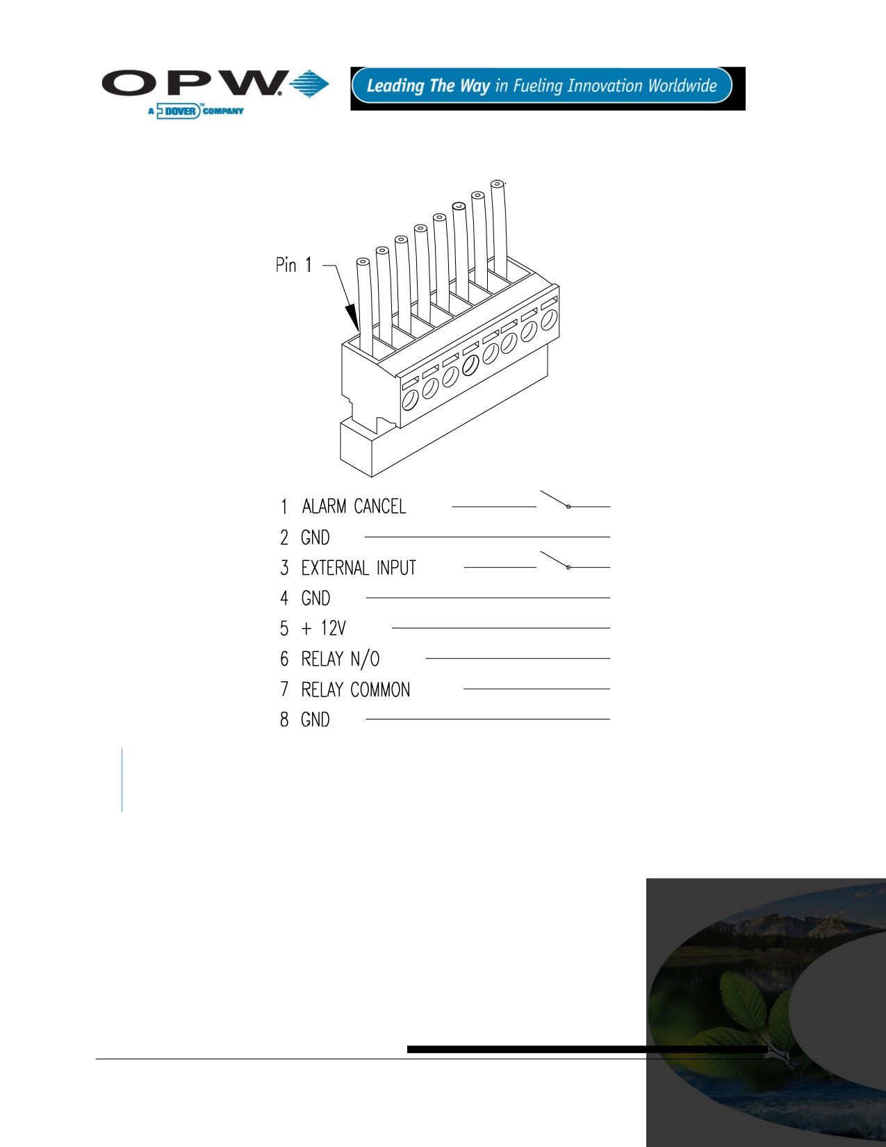
16 Terminal Block Detail
Figure 16-1 SiteSentinel iTouch Terminal Block Connections
If using the external alarm option (see page 83), connect an ALARM CANCEL button across terminals 1
and 2.
Page 78 of 123

17 Printer Option
1. Mount the printer bracket - see Figure 4-2 on page 18.
2. Slide the printer into the wall bracket.
3. Attach 9-pin Dsub connector to the printer and the other end to the Controllers RJ-45 connector - see
Figure 14-1 on page 76.
4. Plug in the printer’s power cable that exits from the 9-pin Dsub.
5. Set DIP switches in printer. See tables in the suction. Refer to the printers operating instructions for
paper loading and testing.
The printer is factory-configured with the default settings in Table 17-1, Table 17-2 (below) and Table 17-3
(page 80). These settings will allow the printer to function properly. If for any reason you need to re-configure
the printer refer to the printer’s operating instructions.
Table 17-1 Printer DIP Switch 1 Settings
Switch #1
Setting
Function
1
OFF
Serial input
2
ON
High printing speed
3
ON
Auto paper loading
4
OFF
No line feed after carriage return
5
ON
DIP SW enabled
6
OFF
Print density 100%
7
ON
8
ON
Table 17-2 Printer DIP Switch 2 Settings
Switch #2
Setting
Function
1
ON
40 columns
2
ON
High printing speed
3
ON
Ordinary characters
4
ON
Normal zero
5
ON
American character set
6
ON
7
ON
8
OFF
Page 79 of 123

Table 17-3 Printer DIP Switch 3 Settings
Switch #3
Setting
Function
1
ON
8 data bits
2
ON
No parity
3
ON
Odd parity
4
ON
Hardware flow control
5
OFF
6
ON
Baud Rate 19,200
7
ON
8
OFF
17.1 Modem Connections
If you purchased your SiteSentinel® iTouch™ with the internal modem option (OPW Fuel Management
Systems part number 75-2042), the modem will have come pre-installed.
Connect the phone line from the junction box to the controller using the supplied RJ-11 cable. See Figure 15-1
on page 77 for the Phone Line port location.
If you are upgrading an existing system with the internal modem you will need to set the dip switch to internal
modem before inserting the modem into its socket.
If the internal modem is not installed, or if you are using an external modem, the dip switch must be set to
external modem.
When using an external modem, attach the modem to the external modem port using an external modem cable
(OPW Fuel Management Systems part number 20-1517-04). See Figure 15-1 on page 77 for the External
Modem port location.
Page 80 of 123
18 CAP Connection for SiteConnect™ Software
Plug in the battery before configuring the SiteSentinel® iTouch™.
The SiteSentinel® iTouch™ Controller is normally configured using the supplied direct connect cable and
SiteConnect™ Windows® software. Connect the RJ-45 end of the cable into the CAP port on the controller and
the other end of the cable into one of your PC’s serial ports. See Figure 15-1 on page 77 for the CAP port
location.
The SiteSentinel® iTouch™ Controller configuration can be modified remotely using the modem connections
described above. SiteConnect™ is required on the remote PC.
After installing the SiteConnect™ software, consult the SiteConnect™ help file for configuration details.
You can also use SiteConnect™ to send or upgrade SiteSentinel® iTouch™ software (see Appendix D -
Upgrading SiteSentinel® iTouch™ Software Via SiteConnect™ on page 86).
If a software upgrade fails, change the connection speed to 19,200 and try to connect to the SiteSentinel®
iTouch™ Controller again.
18.1 POS Interface Option
The SiteSentinel® iTouch™ system can be interrogated by an in-store POS device via the SiteSentinel®
iTouch™ POS port.
Please contact OPW Fuel Management Systems for details.
See Appendix C - POS Interface page 85.
18.2 Built-in TCP/IP Connections
SiteSentinel® 1 is equipped with built-in TCP/IP port and supports DHCP function. For port location, please
refer to Figure 15-1 on page 77. The controller will automatically accept the TCP/IP address assigned by local
LAN.
Page 81 of 123

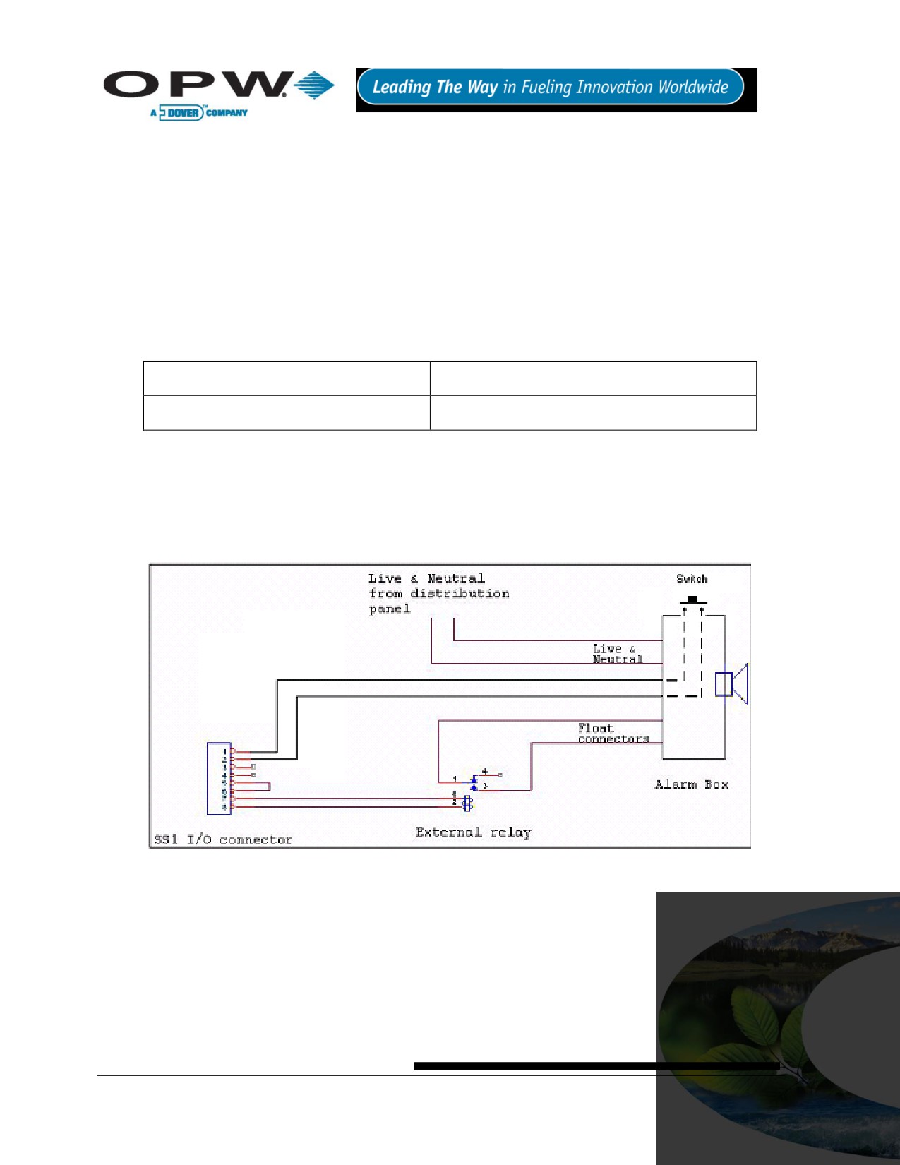
20 Appendix B - Alarm Kit Option
20.1 Alarm Kit Part Numbers
30-2015 (115 VAC)
30-2015-230 (230 VAC)
The Alarm Box requires mains/line voltage (see Figure 20-1 on page 83). Obtain power from the distribution
panel and run the wiring through steel conduit. Use 14-gauge gas and oil-resistant cable.
The Alarm Box requires an external relay. This relay is not supplied with the Alarm Kit - obtain a relay with the
specifications given in Table 20-1 below.
Table 20-1 External Alarm Relay Specifications (NOT Supplied)
Coil Rating
12 VDC @ less than 100 mA
Contact Rating
115 or 230 VAC @ greater than 500 mA
20.2 Installation
1. Install the relay in an external 4” x 4” electrical box or other suitable enclosure.
2. Run rigid conduit from the SiteSentinel® iTouch™ Controller to the relay enclosure.
3. Run the same kind of conduit from the relay enclosure to the Alarm Box.
Figure 20-1 External Alarm Wiring
The Alarm Box will sound its horn and illuminate its light when the contacts close in the SiteSentinel® iTouch™
Controller.
Press the SILENCE button on the Alarm Box to silence the horn. The Alarm Box light, however, remains
illuminated for as log as the contacts in the SiteSentinel® iTouch™ Controller are closed or the switch is
pressed.
Attach a switch across position 1 and 2 (see Figure 20-1 above) to energize or de-energize an external relay.
Page 83 of 123

20.3 Alarm Kit Connections
See Figure 20-1 above. Connections are also listed in the table in Table 20-2 below.
Table 20-2 Alarm Kit Connections
From
To
Switch
Controller I/O connector PINS 1 and 2
Relay Coil
Controller I/O connector PINS 7 and 8
Relay NORMALLY OPEN contacts
Alarm Box FLOAT connectors
Live and neutral AC from distribution panel
Alarm Box AC1 and AC2 connectors
Page 84 of 123

21 Appendix C - POS Interface
This Appendix covers the physical connection between the SiteSentine1 and the Tokheim Fuel POS system.
21.1 SiteSentinel® iTouch™ POS Port
If you order the SiteSentinel® iSite™ Automatic Tank Gauging System with the POS option, you’ll get a cable,
part number 20-1586.
Use SiteConnect™ (from main menu: Configuration > SiteSentinel iTouch Port Parameters) to program the
following:
Data Bits: 8
Parity: NONE
Stop Bits: 1
Port: POS
Connect Speed: 1200
Click OK when done to save the settings.
21.2 Prepare and Attach the Cable
See Figure 21-1 below to prepare a cable to connect the Enraf to the SiteSentinel® iTouch™ POS port.
Figure 21-1 Pinout for POS-to-SiteSentinel® iTouch™ Cable
Page 85 of 123
22 Appendix D - Upgrading SiteSentinel® iTouch™ Software Via
SiteConnect™
The following steps describe the procedure used to upgrade the SiteSentinel® iTouch™ Controller’s software
using the Hardware Flash Update Feature:
1. Connect PC to the controller (Port C, the 3rd from the top).
2. Launch the SiteConnect™ application.
You must be running SiteConnect™ version 2.8.10 or higher.
3. Click the (New Profile) icon to create a new site profile.
4. Enter “1-2” in the Site Telephone # field and click OK
5. Give it a Profile File Name (in the format xxxxx.pro) and click OK.
6. Click the (Direct Connect) icon to connect to the controller.
7. Select a Port and a Connect Speed and click OK.
8. Acknowledge all the dialog boxes that follow.
9. Choose Controller > Retrieve SiteSentinel iTouch Configuration.
10. Click Proceed
11. Acknowledge all of the dialog boxes that follow.
12. Select File > Save to save the profile.
13. Select Configuration > SiteSentinel iTouch Port Parameters
14. Change the POS port to a CAP/Modem port.
15. Change the CAP/Modem speed to 19,200 and then click OK.
16. Acknowledge all of the dialog boxes that follow
17. Select Tools > Hardware Flash Update.
18. Select the new SS1.bin file to be downloaded to the controller and then click OK
19. Click OK to the Send Flash Update to SiteSentinel iTouch Controller? prompt.
20. Click OK to the SiteSentinel iTouch Ready to Receive the Update prompt.
21. Wait until the download is complete (about 15 minutes).
22. Acknowledge all of the dialog boxes that follow.
23. Connect by selecting the (Direct Connect) icon and leave 19,200 for the communication speed.
24. Click OK.
25. Acknowledge all of the dialog boxes that follow.
26. Select Configuration > SiteSentinel iTouch Port Parameters
27. Change the POS Port to the CAP/Modem Port.
28. Change the CAP/Modem speed to the original 9600 baud connection speed and click OK.
29. Acknowledge all of the dialog boxes that follow.
30. Select Tools > Remote Cold Start.
Page 86 of 123
31. Acknowledge all of the dialog boxes that follow.
32. Select File, then open the profile you saved earlier.
33. Click the (Direct Connect) icon to connect to the controller.
34. Select the appropriate communication parameters and click OK.
35. Acknowledge all of the dialog boxes that follow.
36. Select Controller > Restore.
37. Disconnect from SiteConnect™.
The download is complete. Verify the system is functioning properly.
Page 87 of 123
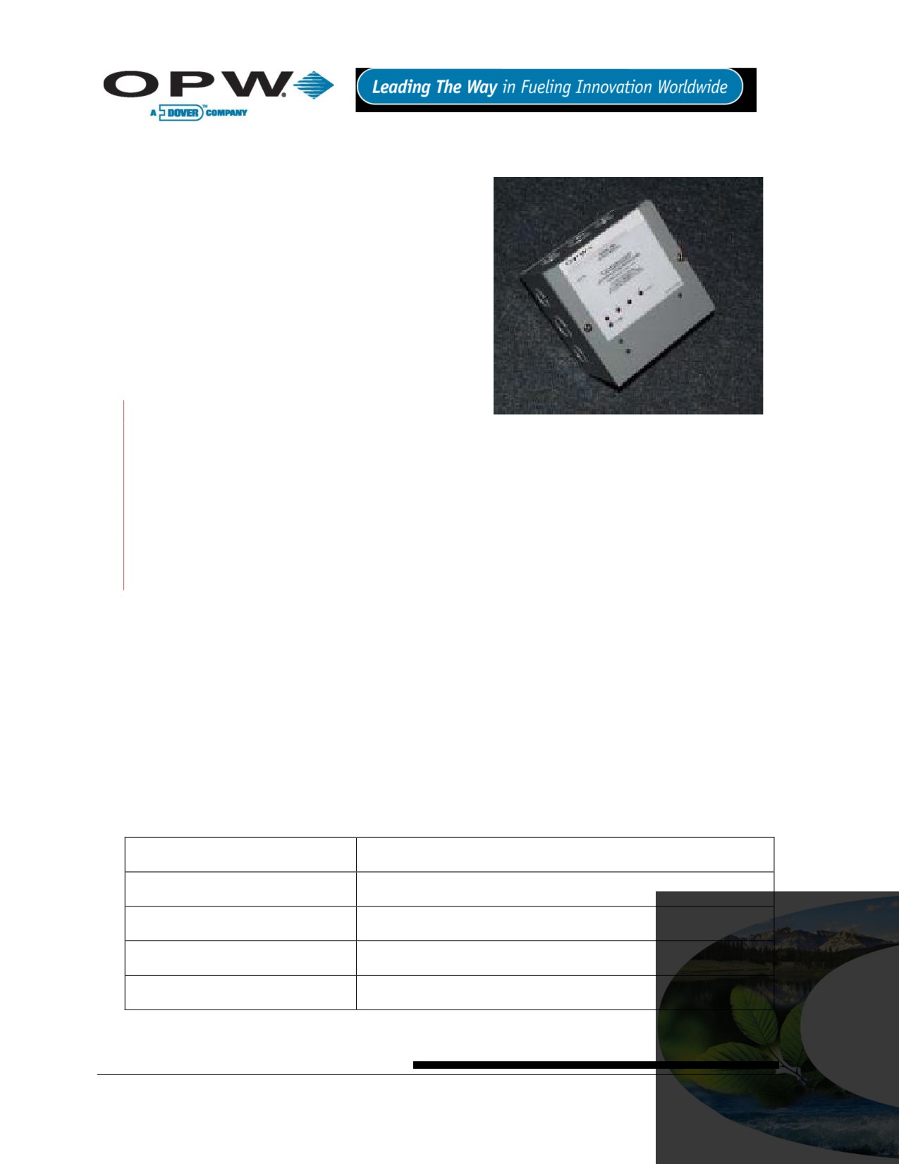
23 Appendix E - OM4 Output Module Option
The optional OM4 Output Module expands your
SiteSentinel® iTouch™ capabilities by letting you connect as
many as eight (8) output devices to the SiteSentinel®
iTouch™ Controller. The OM4 Output Module
communicates with the controller via a single-wire
communication port. Up to two (2) OM4 Output Modules
can be connected for a total of eight (8) output devices.
A common Output Module application is to turn off a
submersible pump when low product is detected in the tank.
Or, use it to activate an audible alarm when high product is
detected in a tank.
See SiteConnect™’s Online Help to program the alarms or
events and to associate them with the Output Module.
DO NOT connect the OM4 Output Module directly to a
submersible pump! The OM4 Output Module controls pumps INDIRECTLY, through relays or contactors.
High voltages exist inside the OM4 Output Module. Only qualified technicians should open the unit.
Before working on the OM4 Output Module, disconnect all power, including power to and from the
relays.
Output relays in the OM4 Output Module are not intrinsically safe! Do not PLACE PROBE AND/OR
SENSOR WIRING IN CONDUIT THAT CONTAINS WIRING FOR DEVICES CONNECTED TO THE OM4
Output Module.
23.1 Codes
Relay wiring is classified Class 1 wiring.
Installations must be in accordance with the National Electrical Code (NFPA No. 70) and the
Automotive and Marine Service Station Code (NFPA No. 30A). The installer is responsible to
investigate and follow any applicable local codes.
23.2 Hazardous Area Definition
A fuel dispenser is a hazardous area as defined in the National Electrical Code. Do not mount the OM4 Output
Module within a hazardous area. Do not attach this unit to any devices that are located in the hazardous area.
23.3 OM4 Output Module Specifications
Table 23-1 Wiring Connections for Alarm Kit
Field Wiring Rating
221ºF (105°C), 600V Type RH. TW, RFH-2 or equal
Power Requirements
12VDC, 0.5A Max. provided by SS1 controller
Dimensions
6” W x 6” H x 4” D (15 cm x 15 cm x 10 cm)
Ambient Temperature
32°F - 104°F (0°C - 40°C)
Relay OUTPUT Rating
5A @ 240 VAC / 5A @ 24 VDC
Page 88 of 123

23.4 Installing the OM4
1. Choose a location for the first OM4 Output Module
within the six-foot reach of the supplied DIN cable
Remove this
(OPW Fuel Management Systems part number 20-
plug
1582).
If installing a second OM4 Output Module, place it
within four feet of the first. Longer distances may cause
improper operation. Allow room at the bottom of the
module(s) for conduit.
2. Remove the cover/module assembly from each
OM4 box.
3. Mount each box to a wall using the box’s four (4)
mounting holes.
If installing two
(2) OM4 Output Module boxes, run
dedicated steel conduit between them for the additional
Figure 23-1 SS1-to-OM4 Connection
power and communication wiring.
Run steel conduit for the relays to a knockout on the
bottom of EACH box. When installing two OM4 Output
Module boxes, DO NOT route the relay wiring through
box to the other! Doing so may cause improper
operation. Pull all relay wiring through the conduit(s).
4. See Figure 23-1. Remove the metal plug from the
right side of the SiteSentinel® iTouch™ Controller to
expose the DIN connector inside.
5. See Figure 23-2. Attach the DIN connector on the
20-1582 cable to the controller
6. Route the other end of the 20-1582 cable through
the supplied bushing/strain relief.
7. Insert the bushing into a knockout hole in the first
OM4 Output Module box. Secure the bushing to the
box.
Figure 23-2 DIN Connector Access
The field wiring terminal locks are removable to ease
installation.
Page 89 of 123

See Figure 23-3 below. Connect the red and black wires from the 20-1582 cable to the first OM4 Output
Module’s POWER terminals (order not important). Connect the green (or brown) wire to the SIGNAL terminal.
Figure 23-3 OM4 Output Module Wiring
When installing two (2) OM4 Output Module boxes, cut off the round DIN end of the remaining 20-1582
cable and use it to daisy-chain the POWER and SIGNAL terminals together. Route this cable through the
conduit connecting the boxes installed earlier.
1. Connect all relay field wiring to the correct terminal block(s).
2. See Figure 23-4 right. When installing two OM4 Output Module
boxes, place the address jumper on the second OM4 on the second
row of pins as shown. To do this, take off the four (4) nuts securing
the aluminum cover and remove it, exposing the circuit board. Set the
jumper and replace the cover.
3. Reinstall each cover/module assembly to their boxes.
Install on
2nd row up
from bottom
Figure 23-4 Address Jumper
for #2 OM
Page 90 of 123

24 Appendix F - LPG Probe Option
This appendix tells you how to install the optional 30-1510, 30-1511 and 30-1512 kits for LPG probes 30-B-xxx
and Q400-xxx.
24.1 About the LPG Probe
24.1.1 30.1510 Probe Kit (Figure 41) Contents
Figure 24-1 What's Supplied in the 30-1510 Kit
1 - Micro-DC plug pole 6 ft Cable
1 - Heat-shrink tubing
1 - Retaining clip
3 - Silicone wire nuts
1 - Float
Page 91 of 123

24.2 30-1511 Probe Kit (Figure 24-2) Contents
This kit is used with the Q0400-xxx, 1500, 2000, and Galaxy.
Figure 24-2 What's Supplied in the 20-1511 Kit
1 - Micro-DC Plug Pole 6 ft Cable
1 - Retaining Clip
3 - Silicone Wire nuts
1 - Float
24.2.1 Head Cover Kit (Figure 24-3) Contents
Figure 24-3 30-1512 Head Cover Kit Contents
1 - 3/8 NTP Cable Bushing
1 - Head Cover
Page 92 of 123

24.3 Installing the LPG Probe
Refer to Figure 24-4 below while working on the probes. Unless noted, instructions apply to both probe types.
Figure 24-4 Probe Assembly and Installation Overview
1. Slide the float onto the bottom of the probe fixture with the magnet pointing up.
2. Place the retaining c-clip ring into the slot on the bottom of the probe fixture shaft.
3. With another person assisting you, carefully raise the probe fixture assembly and insert it into the
treaded opening of the tank.
To avoid damage, use care when the float is near the threaded tank opening!
Page 93 of 123
Complete steps 4 and 5 by following local regulations and tank manufacturer recommendations.
4. Apply a sealant (not included) approved for LPG use to the threads of the flange.
5. Firmly tighten the flange to the LPG tank for a proper seal.
The following 3 steps are for 30-B-xxx probe ONLY
Carefully slide the supplied shrink tubing over the probe outer shaft. Make sure it covers the entire
probe shaft.
Cut the tubing, leaving an extra 2.5 cm (1 in) at the bottom of the probe.
Carefully heat the shrink tubing using a heat gun or similar approved device until the tubing seals
around the probe. Be careful to not over-heat the tubing or it will split.
When shrinking the tubing at the bottom of the probe carefully bond the tubing towards the bottom of
the probe to ensure that the bottom of the probe is covered.
The following step applies only to the Q0400-xxx probe
This probe does not need the shrink tubing.
6. Go to the next step. Remove the protective cap from the open end of the probe fixture assembly.
7. Gently insert the probe into the probe fixture opening. For SiteSentinel® probes, make sure the shrink
tubing is not damaged during this process.
8. Be sure the probe is completely seated in the bottom of the probe fixture.
9. Make all electrical connections using instructions supplied with the probe. Inspect the head cover
assembly BEFORE you complete the electrical connections.
The remaining steps apply to the probe head cover ONLY
The probe head must be covered. Purchase a cover from OPW, order part number 30-1512 (Figure 24-3 on
page 92). You can cut the cover for clearance, but make sure you leave room for connections and cable
(Figure 24-4 on page 93).
1. Insert the cable through the bushing.
2. Insert the connector end of the probe cable into the threaded hole on the top of the head cover.
3. Thread the bushing into the hole on the top of the head cover.
4. Tighten the bushing with the lower molded nut (not the top compression nut).
Do not over-tighten the nut! It isn’t necessary for the bushing to be flush with the top of the head cover.
5. Pull just enough cable through the bushing so that the cable extends from the bottom of the head
assembly.
6. Tighten the compression nut to seal the fitting to the cable.
This completes the LPG probe installation.
Page 94 of 123

25 Appendix G - Probe Comparison
25.1 Model 924 and 924B Magnetostrictive Probe Probe Comparison
Starting in October 2006, OPW Fuel Management Systems began switching from the Model 924
magnetostrictive probe to Model 924B probe. While taking on a new physical appearance, the Model 924B
probe is fully backward compatible with all SiteSentinel® family ATG consoles, as illustrated below:
Compatible with all current SiteSentinel® family ATG controllers
Same installation procedures, including wiring, I.S. barrier, floats and cable
Same configuration procedures
Capable of EPA 0.1 GPH (0.38 liter per hour) and 0.2 GPH (0.76 liter per hour) leak detection
Both certified to UL/US/Canada, ATEX and, additionally on the model 924B, IECEX
While fully backward compatible with the Model 924, the 924B is engineered with the following improvements:
Available EPA 0.1 GPH (0.38 liter per hour) leak detection now third-party certified with 2 in (5 cm)
diameter floats
All stainless-steel construction (stainless-steel probe head and probe shaft)
Conformal-coated circuit board with 100% Surface Mount Components
Smaller overall head diameter - .2 in (3 cm) diameter - and shorter probe head - 8 in (20 cm) long
25.2 Ordering the New Probe
As for order entry, the same probe length calculation is kept while changing the model/part number from 30-
EAxxx to 30-Bxxx. For example, if ordering a probe for a 4 ft (122 cm) diameter tank, instead of part number
30-EA053 for a 924 probe, you should now order 30-B053. Other probe sizes, and their part number
correlation, are shown in Table 21 below:
Table 25-1 924 Probe Conversion Chart
924 (Current)
Equivalent 924B (New)
Descriptions
30-EA053
30-B053
Probe for 4 ft (122 cm) Diameter/Height Tank
30-EA069
30-B069
Probe for 5 ft (152 cm) Diameter/Height Double-Wall Tank
30-EA077
30-B077
Probe for 6 ft (183 cm) Diameter/Height Tank
30-EA089
30-B089
Probe for 7 ft (213 cm) Diameter/Height Tank
30-EA101
30-B101
Probe for 8 ft (244 cm) Diameter/Height Tank
30-EA105
30-B105
Probe for 8 ft (244 cm) Diameter/Height Double-Wall tank
30-EA113
30-B113
Probe for 9 ft (274 cm) Diameter/Height Tank
30-EA125
30-B125
Probe for 10 ft (305 cm) Diameter/Height Tank
30-EA137
30-B137
Probe for 11 ft (335 cm) Diameter/Height Tank
30-EA149
30-B149
Probe for 12 ft (366 cm) Diameter/Height Tank
Page 95 of 123
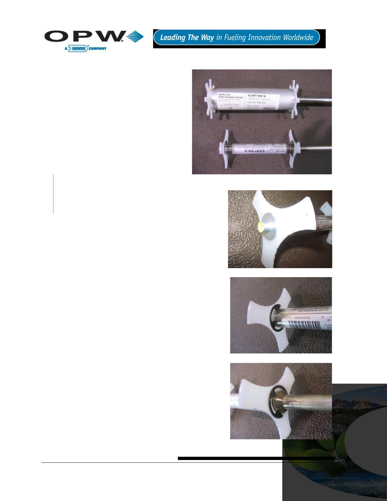
25.3 Probe Installation
Riser: as the new 924B probe head is 1 in
(2.54 cm) shorter than the 924 Probe, there
will be slightly more installation clearance
within any given riser (see Figure 25-1
below)
Wiring: The 924B probe must be installed
using Belden 88760 cable terminating on
the same cable connector at the head
Configuration: The configuration process
remains the same as current 924 probes.
For details, please refer to a SiteSentinel®
iTouch™ 2 or 3 installation manual and/or
SiteConnect™ software help file.
All 924B probes will be shipped out from the
Figure 25-1 924 vs. 924B Probe Head
factory with two plastic stabilizers installed. Should there be
any reason to reinstall the plastic stabilizers and the E-Clip
retainers, please do the following:
1. Twist white plastic stabilizer to open it and slide it onto
the top of the probe head, butting it up against the end of
the probe head as shown (See Figure 25-2).
2. Starting at the bottom of the probe, slide on an E-clip all
the way up the probe shaft until it locates in the grove
directly below the top stabilizer as shown in Figure 25-3
(You will need to push the clip past the lower two grooves
on the probe head that are used to locate the second
Figure 25-2 Top Stabilizer
stabilizer).
3. Slide the second E-Clip up the probe shaft and locate it in
the second of the two grooves found on the probe head,
twist a second stabilizer onto the probe head and butt it
up against the E-Clip. Finally, slide a third E-Clip up the
probe shaft and locate it into the groove as shown in
Figure 25-4, clamping it between the two E-Clips.
4. Put on the clip at the bottom of the probe head.
Figure 25-3 Top Clip
Figure 25-4 Lower Stabilizer and Clip
Page 96 of 123
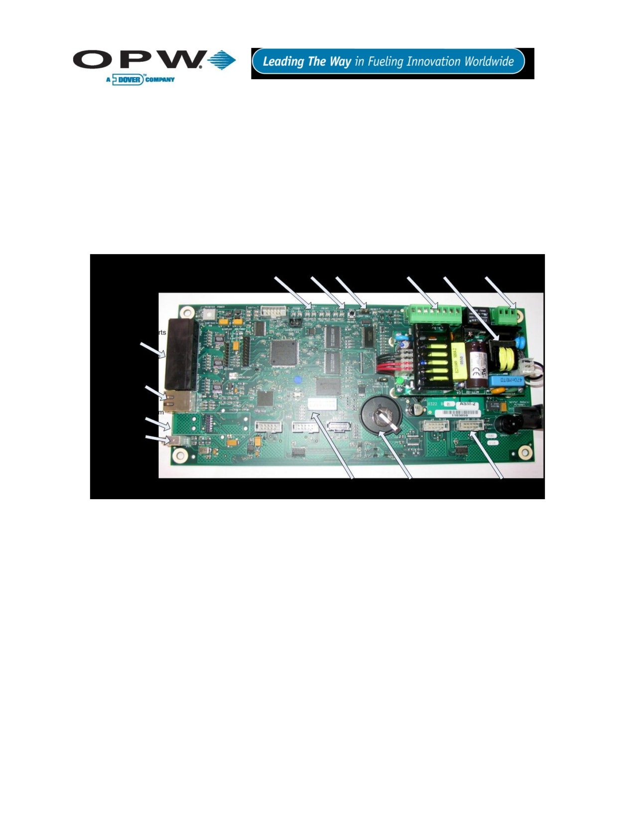
26 Appendix H - Hardware for SiteSentinel® iTouch™ Controller Main
Board
OPW Fuel Management Systems has released a new SiteSentinel® ITouch™ Controller Mai Board (0322
Board). The board is found in Series 2 SiteSentinel® Model 1 ATG Consoles.
26.1 Hardware Overview
The SiteSentinel® iTouch™ Controller Main Board (0322) performs the same functions as the previous
SiteSentinel® iTouch™ 0320 board, although it has several hardware differences and can support some
enhanced software features when used with the latest release of SiteConnect™ PC software.
The new SiteSentinel® iTouch™ board (0322) is shown in Figure 26-1 below:
Figure 26-1 SSI Board (0322)
Page 97 of 123

Below is a comparison chart of the current (0320) and new (0322) SiteSentinel® iTouch™ Main Board:
Table 26-1 Comparison chart of the current (0320) and new (0322) SiteSentinel iTouch main board
Items
SS1 0320 Board
New SS1 0322 Board
Display
Current
No Change
Keypad
Current
No Change
Enclosure & Door
Current
No Change
I.S. Barrier
Current
No Change
Probe
924 A & B
924 A & B
Output Relay Module
OM4 Module
No Change
Terminal Block Wiring
Current
No Change
Power Plug Wiring
Current
No Change
Option (ESN) Chips
Current
No Change
Communication Ports
POS
Current
No Change
Printer
Current
No Change
CAP
Current
No change
External Modem
Current
No Change
TCP/IP
External
Built-in native support
Internal Modem
Current
New (Fax/Modem)
USB
N/A
Available soon
Power Supply
Built-in
Separate
Boot Strap Code
None
New pre-programmed
Boot Loader
On removable chip
New
SS1 Application
On removable chip
New
Site Connect Version
3.0 or above
7.x or above
RAM Battery
2032
3032
Page 98 of 123
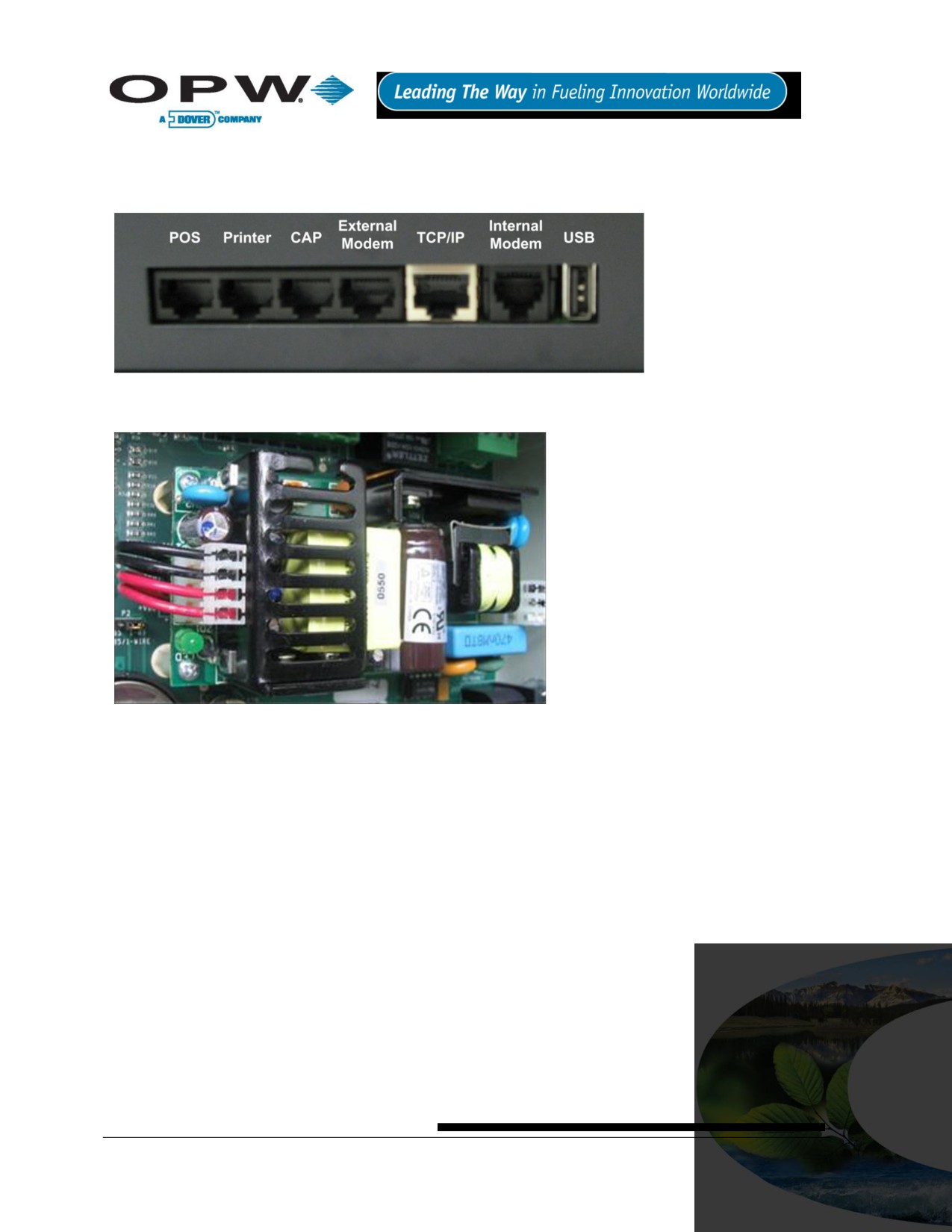
26.2 Hardware Detail
26.2.1 Communication Ports
Figure 26-2 Communication Ports
Power Supply: Separate power supply board.
Figure 26-3 Power Supply
Page 99 of 123

26.3 Status Indicators
CAP/Modem Port
Probe Status
Status
Controller
Printer Status
POS Status
Reset
Figure 26-4 Status Indicators
Flashing LEDs indicate certain current activities of a specific device, which follows:
RX: Receiving data
TX: Sending data
CTS: Clear to send
26.4 Dip Switch
Figure 26-5 DIP Switch
DIP Switch 1 is used for internal selection ONLY. Use the “On” position to select external modem; the
“Off” is for internal modem. Once the dip switch is changed, the SiteSentinel® iTouch™ controller needs
to be restarted. Dip Switch 3 is to select display type. Use “ON” for touch screen and “OFF” for keypad.
Page 100 of 123