Index Nissan Nissan Terrano r20e - Service and Repair Manual
Search
Content .. 189 190 191 192 ..
Nissan Terrano r20e. Manual - part 191
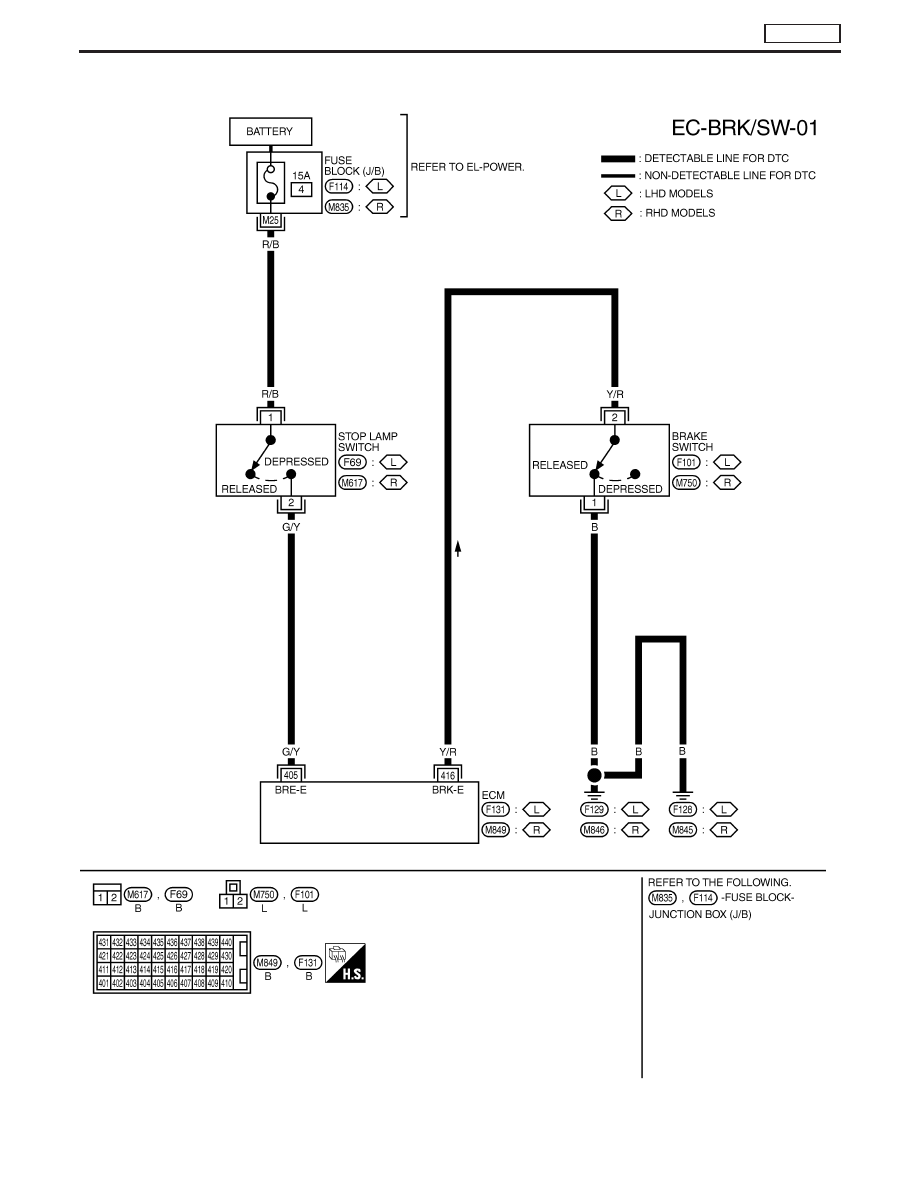
Wiring Diagram
YEC148A
DTC P0571 BRAKE SW
TD27Ti
EC-401