Index Nissan Nissan Teana J32 (2008 year) - Service and Repair Manual
Search
Content .. 624 625 626 627 ..
Nissan Teana J32. Manual - part 626
GI-8
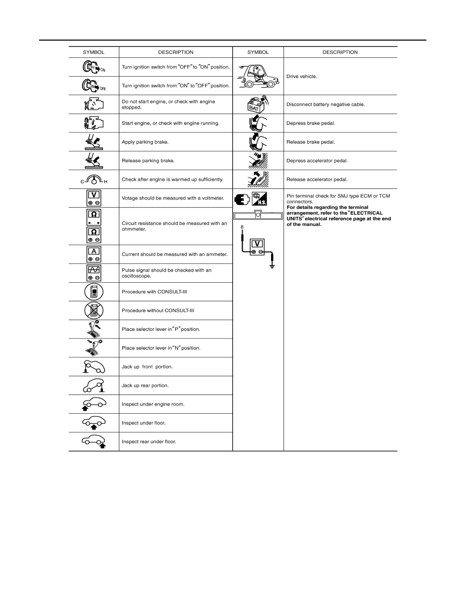
< HOW TO USE THIS MANUAL >
HOW TO FOLLOW TROUBLE DIAGNOSES
SAIA1540E