Mazda Engine LF, L3. Manual - part 8


  Index      Mazda     Mazda Engine LF, L3 - service repair manual 2005 year


Search            


Content   ..  6  7  8  9   ..


Mazda Engine LF, L3. Manual - part 8


MECHANICAL 

01–10–15

01–10

End Of Sie

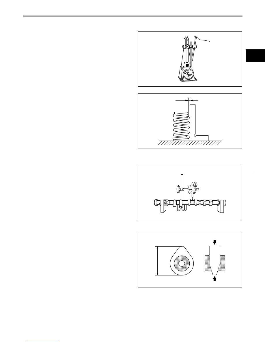
VALVE SPRING INSPECTION

E5U011012125E01

1. Apply pressing force to the pressure spring and inspect the spring height. 

• If it is less than the specification, replace the 

valve spring.

Valve spring pressing force

390 N {39.76 kgf, 87.67 lbf}

Valve spring standard height H

28.68 mm {1.129 in}

2. Measure the out-of-square of the valve spring, 

using a square, as shown in the figure.
(1) Rotate the valve spring one full turn and 

measure "A" at the point where the gap is the 
largest.

• If it exceeds the specification, replace the 

valve spring.

Valve spring out-of-square (Maximum)

1.95 mm {0.0767 in}

End Of Sie

CAMSHAFT INSPECTION

E5U011012420E01

1. Set the No.1 and No.5 journals on V-blocks. 
2. Measure the camshaft runout.

• If it exceeds the specification, replace the 

camshaft.

Maximum runout (Maximum)

0.03 mm {0.0012 in}

3. Measure the cam lobe height at the two points as 

shown in the figure. 

• If it is less than the specification, replace the 

camshaft.

Camshaft standard height (mm {in})

With variable valve timing mechanism
 IN: 42.44 {1.671}
 EX: 41.18 {1.621}
Without variable valve timing mechanism
 IN: 42.12 {1.659}
 EX: 41.08 {1.618}

Camshaft minimum height (mm {in})

With variable valve timing mechanism
 IN: 42.33 {1.666}
 EX: 41.06 {1.616}
Without variable valve timing mechanism
 IN: 42.01 {1.653}
 EX: 40.96 {1.612}

ADJ2224E028

A

UPPER

LOWER

B3E0110E073

B3E0110E074

B3E0110E076

MECHANICAL 

01–10–16

4. Measure the journal diameters in X and Y 

directions at the two points (A and B) as indicated 
in the figure.

• If it is less than the specification, replace the 

camshaft.

Camshaft journal diameter (Standard)

 24.96—24.98 mm {0.9827—0.9834 in}

Camshaft journal diameter (Minimum)

24.95 mm {0.982 in}

5. Remove the tappet.
6. Position a plastigage atop the journals in the axial 

direction.

7. Install the camshaft cap. (See 01–10–37 

Camshaft Assembly Note.)

8. Remove the camshaft cap. (See 01–10–7 

Camshaft Cap Disassembly Note.)

9. Measure the oil clearance. 

• If it exceeds the specification, replace the 

cylinder head.

Camshaft journal oil clearance (Standard)

0.035—0.080 mm {0.0014—0.0031 in}

Camshaft journal oil clearance (Maximum)

0.09 mm {0.0035 in}

10. Install the camshaft cap. (See 01–10–37 Camshaft Assembly Note.)
11. Measure the camshaft end play.

• If it exceeds the specification, replace the cylinder head or camshaft.

Camshaft end play (Standard)

0.09—0.24 mm {0.0035—0.0094 in}

Camshaft end play (Maximum)

0.25 mm {0.0098 in}

12. Remove the camshaft cap. (See 01–10–7 

Camshaft Cap Disassembly Note.)

End Of Sie

A

B

X

Y

B3E0110E075

PLASTIGAUGE

B3E0110E077

B3E0110E078

MECHANICAL 

01–10–17

01–10

TAPPET INSPECTION

E5U011012431E01

1. Measure the tappet hole inner diameter in X and 

Y directions at the two points (A and B) shown in 
the figure.

Tappet bore diameter (Standard)

31.000—31.030 mm {1.2205—1.2216 in}

2. Measure the tappet body outer diameter in X and 

Y directions at the two points (A and B) shown in 
the figure. 

Tappet diameter (Standard)

30.970—30.980 mm {1.2193—1.2196 in}

3. Subtract the tappet body outer diameter from the 

tappet hole inner diameter.

• If it exceeds the specification, replace the 

tappet or cylinder head.

Tappet-to-Tappet bore oil clearance (Standard)

0.02—0.06 mm {0.0008—0.0023 in}

Tappet-to-Tappet bore oil clearance (Maximum)

0.15 mm {0.006 in}

End Of Sie

CYLINDER BLOCK INSPECTION

E5U011010300E01

1. Measure the distortion of the cylinder block top 

surface in six directions as indicated in the figure. 

• If it exceeds the maximum, replace the 

cylinder block.

Cylinder head gasket contact surfaces 

distortion (Maximum)

0.10 mm {0.004 in}

2. Measure the cylinder bores in X and Y directions 

at 42 mm {1.65 in} below the top surface.

• If not within the specification, replace the 

cylinder block. 

Cylinder bore diameter (Standard)

87.500—87.530 mm {3.4449—3.4460 in}

Minimum / maximum bore diameter limit

87.440—87.590 mm {3.4425—3.4484 in}

End Of Sie

X

Y

A

B

ADJ2224E023

A

B

Y

X

ADJ2224E029

ADJ2224E089

42 mm {1.65 in}

X

Y

C3U0110E007

MECHANICAL 

01–10–18

OIL JET VALVE INSPECTION

E5U011010730E01

1. Apply compressed air to oil jet valve A and verify 

that air passes through oil jet valve B.

• If air does not flow, replace the oil jet valve.

Oil jet valve air pressure

216—274 kPa {2.2—2.7 kgf·cm

2

 31.4—39.7 

psi} 

End Of Sie

PISTON INSPECTION

E5U011011010E01

Caution

• The piston and connecting rod cannot be disassembled.

• When replacing the piston, piston pin, piston ring and connecting rod, replace them together as a 

single unit.

1. Measure the outer diameter of each piston at right 

angle 90

° to the piston pin, 10.0 mm {0.40 in} 

above the under of the piston.

• If not within the specification, replace the 

piston, piston pin, piston ring and connecting 
rod as a single unit.

Piston diameter (Standard)

87.465—87.495 mm {3.4435—3.4446 in}

2. Measure the piston-to-cylinder clearance.

• If not within the specification, replace the 

piston, piston pin, piston ring and connecting 
rod as a single unit.

Piston-to-cylinder clearance (Standard)

0.025—0.045 mm {0.0010—0.0017 in}

Piston-to-cylinder clearance (Maximum)

0.11 mm {0.0043 in}

3. Measure the piston ring-to-ring groove clearance around the entire circumference.

• If it exceeds the specification, replace the piston, piston pin, piston ring and connecting rod as a single unit.

Piston ring-to-ring groove clearance 

(Standard)

Top: 0.03—0.08 mm {0.0012—0.0031 in}
Second: 0.03—0.07 mm {0.0012—0.0027 in}
Oil: 0.03—0.07 mm {0.0012—0.0027 in}

Piston ring-to-ring groove clearance 

(Maximum)

Top: 0.17 mm {0.0067 in}
Second, Oil: 0.15 mm {0.0059 in}

A

B

B3E0110E079

B3E0110E080

B3E0110E081


Content   ..  6  7  8  9   ..