Mazda Engine LF, L3. Manual - part 6


  Index      Mazda     Mazda Engine LF, L3 - service repair manual 2005 year


Search            


Content   ..  4  5  6  7   ..


Mazda Engine LF, L3. Manual - part 6


MECHANICAL 

01–10–7

01–10

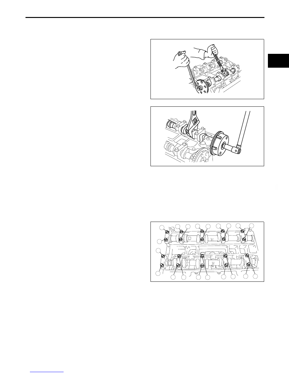
Camshaft Sprocket Lock Bolt, Variable Valve Timing Actuator Lock Bolt Disassembly Note

1. Hold the camshaft by using a wrench on the cast hexagon as shown, and loosen the camshaft sprocket 

installation bolt or variable valve timing actuator installation bolt (With variable valve timing mechanism).

Without variable valve timing mechanism

With variable valve timing mechanism

Camshaft Cap Disassembly Note

1. Before removing the camshaft caps, inspect the following:

— Camshaft end play and camshaft journal oil clearance (See 01–10–15 CAMSHAFT INSPECTION.)

Note

• The camshaft caps are numbered to make sure they are assembled in their original positions. When 

removed, keep the caps with the cylinder head they were removed from. Do not mix the caps.

2. Loosen the camshaft caps bolts in 2—3 steps in 

the order shown in the figure.

Tappet Disassembly Note

Note

• The tappets are numbered to make sure they are assembled in their original positions. When removed, 

keep the tappets with the cylinder head they were removed from. Do not mix the tappets.

B3E0110E056

B3E0110E058

9

8

7

5

4

3

1

2

10

19

18

17

15

16

14

13

11

12

20

6

B3E0110E057

MECHANICAL 

01–10–8

Cylinder Head Bolt Disassembly Note

1. Loosen the cylinder head bolts in 2—3 steps in 

the order shown in the figure.

End Of Sie

CYLINDER HEAD (II) DISASSEMBLY

E5U011002000E05

1. Disassemble in the order indicated in the table.

.

Valve Keeper Disassembly Note

1. Remove the valve keeper using the SSTs.

9

8

7

4

3

1

2

10

5

6

B3E0110E059

8

7

5

4

3

1

1

2

6

SST

SST

R

R

B3E0110E060

1

Engine hanger

2

Valve keeper
(See 01–10–8 Valve Keeper Disassembly Note.)

3

Upper valve spring seat

4

Valve spring

5

Valve

6

Valve seal
(See 01–10–9 Valve Seal Disassembly Note.)

7

EGR  pipe

8

Water outlet

49 B012 0A2

49 0636 100B

B3E0110E124

MECHANICAL 

01–10–9

01–10

Valve Seal Disassembly Note

1. Remove the valve seal using the SST.

End Of Sie

CYLINDER BLOCK (I) DISASSEMBLY

E5U011002000E06

1. Disassemble in the order indicated in the table.

.

49 S120 170

VALVE SEAL

VALVE GUIDE

B3E0110E061

R

R

R

R

R

R

SST

SPIN-ON  

TYPE

CARTRIDGE 

TYPE

WITH OIL COOLER

MTX

R

9

8

7

1

5

4

3

2

13

12

OIL

OIL

R

R

IF EQUIPPED

10

11

R

WITHOUT OIL COOLER

6

6

E5U110ZE7S10

1

Flywheel (MTX), Drive plate (ATX) (See 01–10–10 
Drive Plate (ATX), Flywheel (MTX) Disassembly 
Note)

2

Oil pan

3

Oil filter cover (cartridge type)

4

Oil filter

5

Oil cooler

6

Oil filter adapter

7

Knock sensor

8

Oil separator

9

Thermostat

10

Water pump

11

Oil strainer

12

Oil pump

13

Rear oil seal

MECHANICAL 

01–10–10

Drive Plate (ATX), Flywheel (MTX) Disassembly Note

1. Hold the crankshaft using the SST.
2. Remove the bolts in several passes.

End Of Sie

CYLINDER BLOCK (II) DISASSEMBLY

E5U011002000E07

1. Disassemble in the order indicated in the table.

.

1

2

3

4

5

6

49 E011 1A0

B3E0110E051

9

8

7

5

4

3

1

2

10

6

11

12

L3

L3

10

E5U110ZE7S07

1

Balancer unit

2

Adjustment shim

3

Connecting rod cap
(See 01–10–11 Connecting Rod Cap Disassembly 
Note.)

4

Lower connecting rod bearing

5

Connecting rod, Piston component

6

Piston ring

7

Upper connecting rod bearing

8

Main bearing cap
(See 01–10–11 Main Bearing Cap Disassembly 
Note.)

9

Lower main bearing, thrust bearing

10

Crankshaft

11

Upper main bearing, thrust bearing

12

Oil jet valve


Content   ..  4  5  6  7   ..