Mazda Automatic Transaxle JA5A-EL. Manual - part 35
AUTOMATIC TRANSAXLE
K145
K1
.
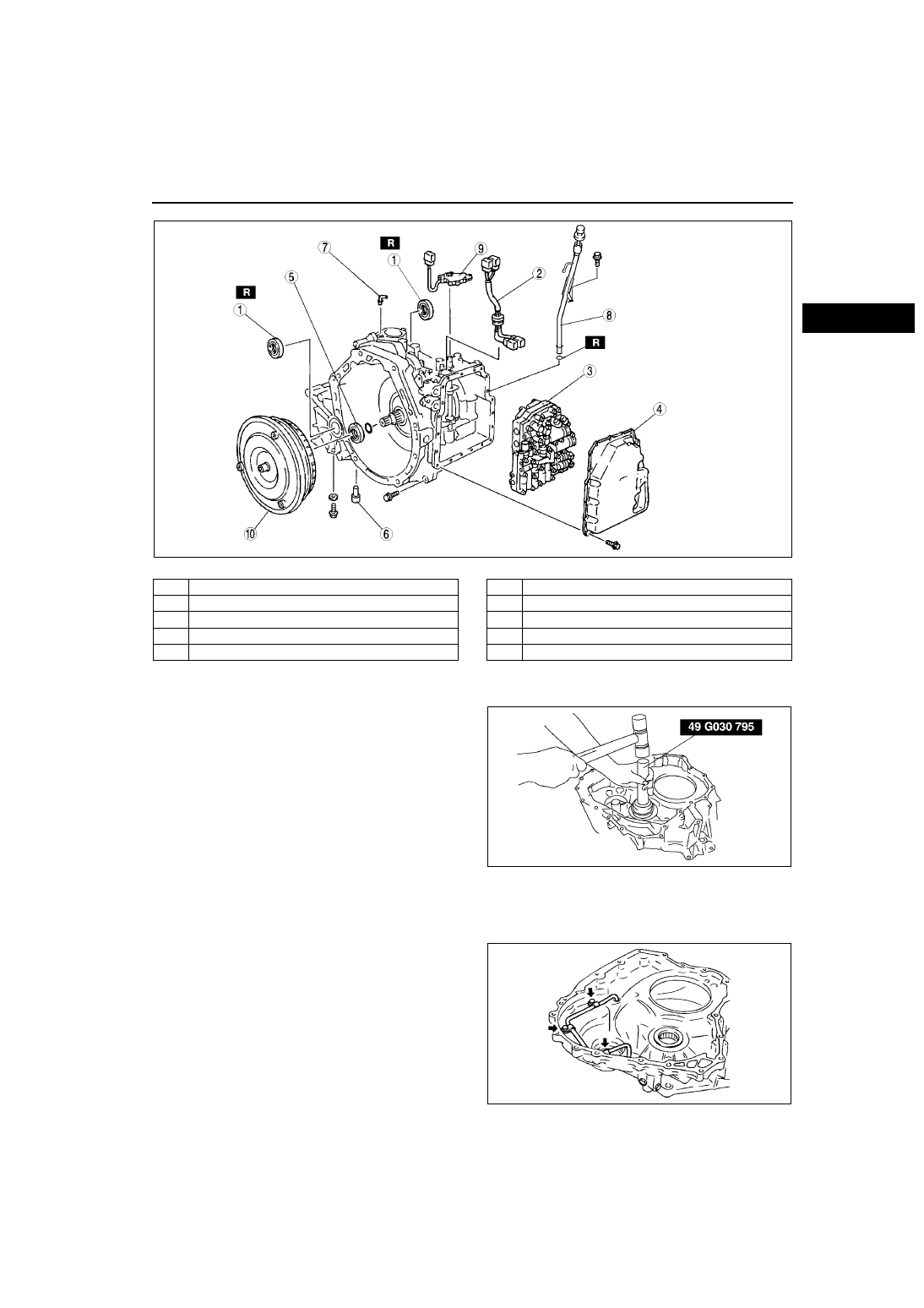
Assembly procedure
1. Using the SSTs and a hammer, install the
reduction gear outer race.
2. Install the oil pipe to converter housing.
(1) Check the oil pipe and seal surface for dents or damage.
• Replace the parts if necessary.
(2) Install the oil pipe.
Tightening torque
4.96.9 N·m {0.50.7 kgf·m, 3.65.1 ft·lbf}
3. Install the baffle plate to the converter housing.
AMJ5614A068
1
Differential oil seal
2
Terminal component
3
Control valve body
4
Control valve body cover
5
Oil seal
6
Drain plug
7
Air breezer
8
Oil filler tube
9
TR switch
10
Torque converter
AMU0517A176
AMU0517A127