Mazda Transaxle FN4A-EL. Manual - part 14


  Index      Mazda     Mazda Automatic Transaxle FN4A-EL - service manual 2002 year


Search            copyright infringement  


Content   ..  12  13  14  15   ..


Mazda Transaxle FN4A-EL. Manual - part 14


K1–48

AUTOMATIC TRANSAXLE 

Caution

••••

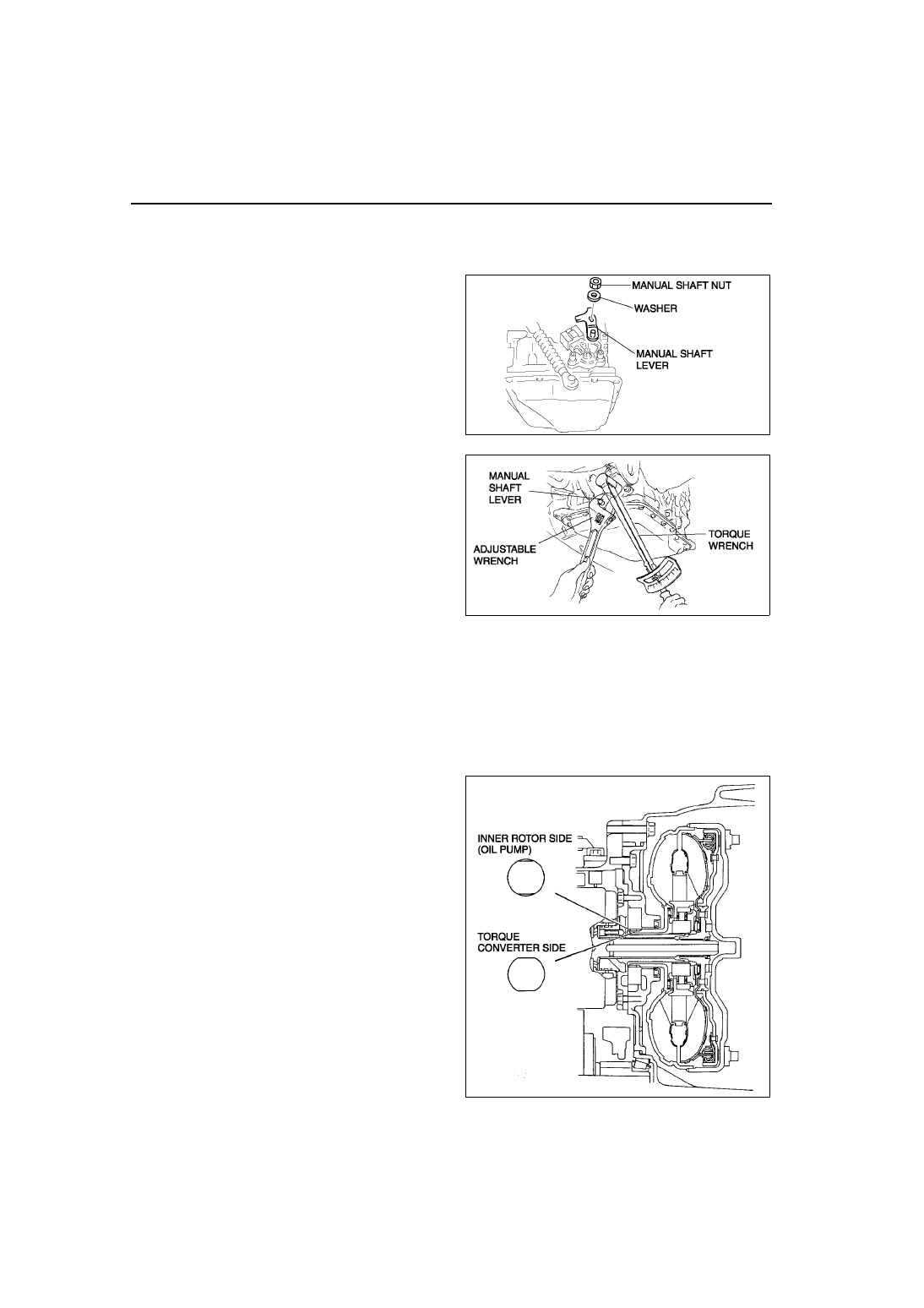
Do not use an impact wrench. Hold the manual shaft lever when removing the manual shaft nut, or 
the transaxle may be damaged.

(7) Install the manual shaft lever and the washer.

(8) Set the adjustable wrench as shown to hold 

the manual shaft lever, and tighten the 
manual shaft nut.

Tightening torque

32—46 N·m 

{3.2—4.7 kgf·m, 24—33 ft·lbf}

62. Remove the transaxle from the SST.
63. Apply ATF to the new O-ring and install it to the oil 

filler tube.

64. Install the oil dipstick and oil filler tube to the 

transaxle.

Tightening torque

7.9—10.7 N·m 

{80—110 kgf·cm, 70—95.4 in·lbf}

65. Drain any ATF remaining in the torque converter.
66. Pour in solvent (approx. 0.5 L {0.53 US qt, 0.44 lmp qt}),
67. Shake the torque converter to clean the inside.
68. Pour out the solvent.
69. Pour the ATF.
70. Install the torque converter by aligning its gap to 

the oil pump inner rotor gap as shown in the 
figure.

A6E5614W012

A6E5614W101

A6E5714A095

AUTOMATIC TRANSAXLE 

K1–49

K1

71. To ensure that the torque converter is installed 

accurately, measure distance A between the end 
of the torque converter and the end of the 
converter housing.

(A): 15.5 mm {0.609 in} (ZL, ZM)

 21.5 mm {0.846 in} (FP, LF,L3)

End Of Sie

AUTOMATIC TRANSAXLE INSPECTION

A6E561401030A03

Torque Converter Inspection

1. Inspect the outer surface of the torque converter for damage or cracks, and replace it if necessary.
2. Inspect for rust on the pilot hub of the torque converter or on the boss. If there is any, remove the rust 

completely.

Oil Pump Preinspection

1. Measure the bushing of the oil pump.

Bushing inner diameter

Torque converter side
Standard: 40.015—40.040 mm 

{1.57539—1.57637 in}

Maximum: 40.060 mm {1.57716 in}

Forward clutch side
Standard: 19.000—19.021 mm 

{0.74803—0.74885 in}

Maximum: 19.041 mm {0.74964 in}

2. If not as specified, replace the oil pump housing 

and oil pump cover. (See Section K.)

Forward Clutch Preinspection
Clutch operation

1. Set the forward clutch onto the oil pump.

Caution

••••

Applying compressed air to the assembled clutch pack for longer than 3 seconds at a time will 
damage the seal. 
Do not apply compressed air for more than the aforementioned time when testing the system.

2. Inspect the clutch operation by applying 

compressed air through the fluid passages 
shown.

Air pressure

392 kPa {4.0 kgf/cm

2

, 57 psi} max.

3. If not as specified, replace parts as necessary. 

(See Section K.)

A6E5714A096

A6E5714A097

A6E5714A098

K1–50

AUTOMATIC TRANSAXLE 

Clutch clearance

1. Measure the forward clutch clearance.

(1) Install the forward clutch in the oil pump, and set the dial gauge.
(2) Secure the forward clutch by lightly pressing 

down with a press, etc.

(3) Apply compressed air to the part indicated in 

the figure and let the forward clutch piston 
stroke three times.

Air pressure

392—441 kPa {4.0—4.5 kgf/cm

2

, 57—63 psi}

(4) Apply compressed air and operate the 

forward clutch piston. Read the value when 
the indicator of the dial gauge stops.

(5) Release the compressed air and read the dial 

gauge when the forward clutch piston is not 
operating.

(6) Calculate the forward clutch clearance 

according to the following formula:
Step (4) value – Step (5) value = Forward clutch clearance.

(7) Measure the clearances at four locations (90

°


apart) by following the steps from (3) to (6). 
Verify that the average value is within the 
specification below.

Forward clutch clearance

1.50—1.80 mm {0.059—0.071 in}

2. If not as specified, replace parts as necessary. 

(See Section K.)

Clutch Component Preinspection
Clutch operation

1. Set the clutch component onto the end cover.

Caution

••••

Applying compressed air to the assembled clutch pack for longer than 3 seconds at a time will 
damage the seal.
Do not apply compressed air for more than the aforementioned time when testing the system.

A6E5714A099

A6E5714A098

A6E5714A100

AUTOMATIC TRANSAXLE 

K1–51

K1

2. Inspect the clutch operation by applying 

compressed air as shown.

Air Pressure

392 kPa {4.0 kgf/cm

2

, 57 psi} max.

3. If not as specified, replace parts as 

necessary.(See 

K1–18 CLUTCH COMPONENT 

DISASSEMBLY/ASSEMBLY

.)

Reverse clutch clearance

1. Measure the reverse clutch clearance.

(1) Install the reverse clutch into the end cover, and set the dial gauge.
(2) Secure the reverse clutch by lightly pressing 

down with a press, etc.

(3) Apply compressed air to the part indicated in 

the figure and let the reverse clutch piston 
stroke three times.

Air Pressure

392—441 kPa {4.0—4.5 kgf/cm

2

, 57—63 psi} 

(4) Apply compressed air and operate the 

reverse clutch piston. Read the value  when 
the indicator of the dial gauge stops.

(5) Release the compressed air and read the dial 

gauge when the reverse clutch  piston is not 
operating.

(6) Calculate the reverse clutch clearance 

according to the following formula: Step (4) value – Step (5) value = Reverse clutch clearance.

(7) Measure the clearances at four locations (90

°


apart) by following the steps  from (3) to (6). 
Verify that the average value is within the 
specificatin below.

Reverse clutch clearance

1.00—1.30 mm {0.039—0.051 in}

2. If not as specified, replace parts as 

necessary.(See 

K1–18 CLUTCH COMPONENT 

DISASSEMBLY/ASSEMBLY

.)

A6E5714A101

A6E5714A041

A6E5714A042

A6E5714A043


Content   ..  12  13  14  15   ..