Mazda Transaxle FN4A-EL. Manual - part 13


  Index      Mazda     Mazda Automatic Transaxle FN4A-EL - service manual 2002 year


Search            copyright infringement  


Content   ..  11  12  13  14   ..


Mazda Transaxle FN4A-EL. Manual - part 13


K1–44

AUTOMATIC TRANSAXLE 

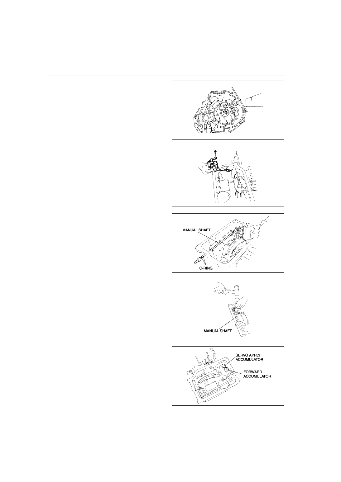
42. Install the oil pump.

Tightening torque

19—25 N·m {1.9—2.6 kgf·m, 14—18 ft·lbf}

43. Install the parking rod lever component.

Tightening torque

19—25 N·m {1.9—2.6 kgf·m, 14—18 ft·lbf}

44. Apply ATF to the new O-ring and install it to the 

manual shaft. 

45. Install the manual shaft.

(1) Install the manual shaft to the manual plate 

and detent bracket component.

(2) Install the knock pin.

46. Install the accumulator component.

A6E5714A110

X3U517AAE

A6E5714A012

A6E5714A011

A6E5714A010

AUTOMATIC TRANSAXLE 

K1–45

K1

47. Install the coupler component.

Caution

••••

Make sure that the head of the manual 
valve and the parking rod are assembled 
properly. If they are not, the ranges 
cannot be changed.

48. Install the control valve body.

Tightening torque

7.9—10.7 N·m 

{80—110 kgf·cm, 70—95.4 in·lbf}

Bolt length (measured from below the head)

B: 40 mm {1.575 in}
No mark: 70 mm {2.756 in}

49. Apply ATF to the new O-ring and install it to the oil 

strainer. 

50. Install the oil strainer.
51. Match the harness colors, then connect the 

solenoid connector and transaxle fluid 
temperature sensor connector.

X3U517AAA

A6E5714A090

A6E5714A091

A6E5714A008

Solenoid valve

Color of connector 

(harness side)

Pressure control solenoid

Black

Shift solenoid A

White

Shift solenoid B

Blue

Shift solenoid C

Green

Shift solenoid D

White

Shift solenoid E

Black

K1–46

AUTOMATIC TRANSAXLE 

52. Install the ground.

Tightening torque

7.9—10.7 N·m

{80—110 kgf·cm, 70—95.4 in·lbf}

Warning

••••

Using compressed air can cause dirt and 
other particles to fly out, causing injury 
to the eyes. Wear protective eye wear 
whenever using compressed air.

Caution

••••

Clean the transaxle exterior thoroughly 
with a steam cleaner or cleaning solvents before removal.

••••

If any old sealant gets into the transaxle during installation of the oil pan, trouble may occur in the 
transaxle case and oil pan, and clean with cleaning fluids.

53. Apply a light coat of silicone sealant to the contact 

surfaces of oil pan and transaxle case.

54. Install the oil pan.

Tightening torque

5.9—7.8 N·m 

{60—80 kgf·cm, 53—69 in·lbf}

55. Install the oil pipe.

Tightening torque

24—35 N·m 

{2.4—3.6 kgf·cm, 18—26 in·lbf}

56. Apply ATF to the new O-ring and install it to the vehicle speed sensor.
57. Install the vehicle speed sensor.

Tightening torque

7.9—10.7 N·m 

{80—110 kgf·cm, 70—95.4 in·lbf}

58. Apply ATF to the new O-ring and install it to the input/turbine speed sensor.
59. Install the oil pressure switch.

Tightening torque

17.1—22.1 N·m 

{1.75—2.25 kgf·m, 12.7—16.2 ft·lbf}

60. Install the input/turbine speed sensor.

Tightening torque

7.9—10.7 N·m 

{80—110 kgf·cm, 70—95.4 in·lbf}

61. Install the transaxle range switch.

A6E5714A092

A6E5714A093

AUTOMATIC TRANSAXLE 

K1–47

K1

(1) Rotate the manual shaft to the N position.

(2) Turn the protrusion a resistance between the 

terminals B and C become 750 ohms.

(3) Install the TR switch while aligning the 

protrusion and groove as shown.

(4) hand- tighten the TR switch mounting bolts.

(5) Inspect the resistance between the terminals 

B and C.

If not as specified, readjust the TR switch.

Resistance

750 ohms

(6) Tighten the TR switch mounting bolts

Tightening torque

8—11 N·m 

{82—112 kgf·cm, 71—97 in·lbf}

A6E5714A094

A6E5614W014

A6E5614W010

A6E5614W016

A6E5614W010


Content   ..  11  12  13  14   ..