Mazda Transaxle FN4A-EL. Manual - part 9


  Index      Mazda     Mazda Automatic Transaxle FN4A-EL - service manual 2002 year


Search            copyright infringement  


Content   ..  7  8  9  10   ..


Mazda Transaxle FN4A-EL. Manual - part 9


K1–28

AUTOMATIC TRANSAXLE 

Assembly Procedure

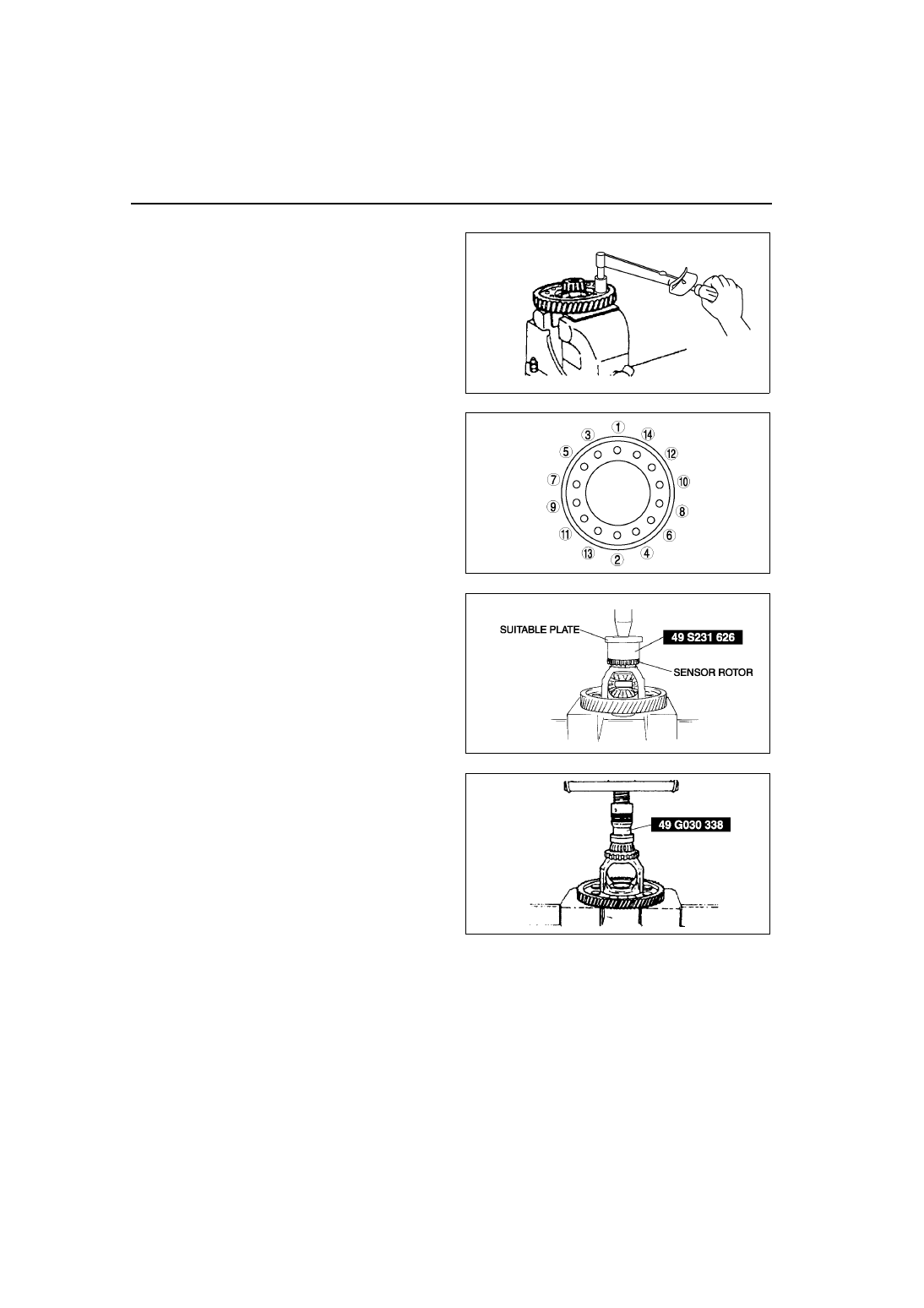
1. Install the ring gear to the gear case. (bolt fixed 

type)

2. Tighten the bolts evenly and gradually in the 

order shown. (bolt fixed type)

Tightening torque

152—176.5 N·m 

{15.5—17.9 kgf·m, 112—130 ft·lbf}

3. Install the sensor rotor to the gear case using the 

SST and suitable plate.

4. Install a new bearing.

(1) Press the new bearing (speedometer drive 

gear side) onto the gear case using the SST.

(2) Press on the other new bearing (ring gear 

side) in the same manner.

5. Apply ATF to the thrust washers and pinion shaft.
6. Install the pinion gear and thrust washers into the 

gear case.

A6E5714A056

A6E5714A057

A6E5714A058

A6E5714A059

AUTOMATIC TRANSAXLE 

K1–29

K1

7. Install the pinion shaft.

8. Install the roll pin, and crimp it to prevent it from 

coming out of the gear case.

9. Apply ATF to the thrust washers.

10. Install the thrust washers and side gears into the 

gear case, then turn the side gears and align 
them with the drive shaft holes.

11. Measure the backlash of the side gears as 

follows:
(1) Install the left and right drive shafts in the 

differential.

(2) Support the drive shafts on V-blocks.

(3) Measure the backlash of both side gears.

Backlash

Standard: 0.05—0.15 mm {0.002—0.005 in}
Maximum: 0.5 mm {0.020 in}

12. If the backlash is not within the specification, 

replace the differential.

End Of Sie

AUTOMATIC TRANSAXLE ASSEMBLY

A6E561401030A02

Precaution
General notes

1. Select the adjustment shims, referring to Bearing Preload.
2. If the drive plates or 2-4 brake band are replaced with new ones, soak the new part in ATF for at least two 

hours before installation.

3. Before assembly, apply ATF to all seal rings, rotating parts, O-rings, and sliding parts.
4. All O-rings, seals, and gaskets must be replaced with the new ones included in the overhaul kit.
5. Use petroleum jelly, not grease, when assembling again.
6. When it is necessary to replace a bushing, replace the subassembly that includes that bushing.
7. Assemble the housing within 10 minutes after applying sealant, and allow it to cure for at least 30 minutes after 

assembly before filling the transaxle with ATF.

Warning

••••

Although the stand has a self-locking brake system, there is a possibility that the brake may not 
hold when the transaxle is held in a lopsided position on the stand. This would cause the transaxle 
to turn suddenly, causing serious injury. Never keep the transaxle tilted to one side. Always hold 
the rotating handle firmly when turning the transaxle.

X3U517AEW

X3U517AEX

A6E5714A060

K1–30

AUTOMATIC TRANSAXLE 

Assembly
Bearing and race locations

Note

The bearing and race at locations 2, 3, 4, 5, and 6 are one-piece units.

Outer diameter of bearing and race

A6E5714A107

1

2

3

4

5

6

Bearing (mm {in})

40.0 {1.57}

40.0 {1.57}

39.0 {1.54}

78.2 {3.08}

52.0 {2.05}

50.0 {1.97}

Race (mm {in})

40.2 {1.58}

AUTOMATIC TRANSAXLE 

K1–31

K1

Components

.

A6E5714A061

1

Converter housing

2

Oil seal

3

Adjustment shim

4

Bearing race


Content   ..  7  8  9  10   ..