Mazda CX-9 Grand Touring. Manual - part 607


  Index      Mazda     Mazda CX-9 Grand Touring - service repair manual 2008 year


Search            


Content   ..  605  606  607  608   ..


Mazda CX-9 Grand Touring. Manual - part 607


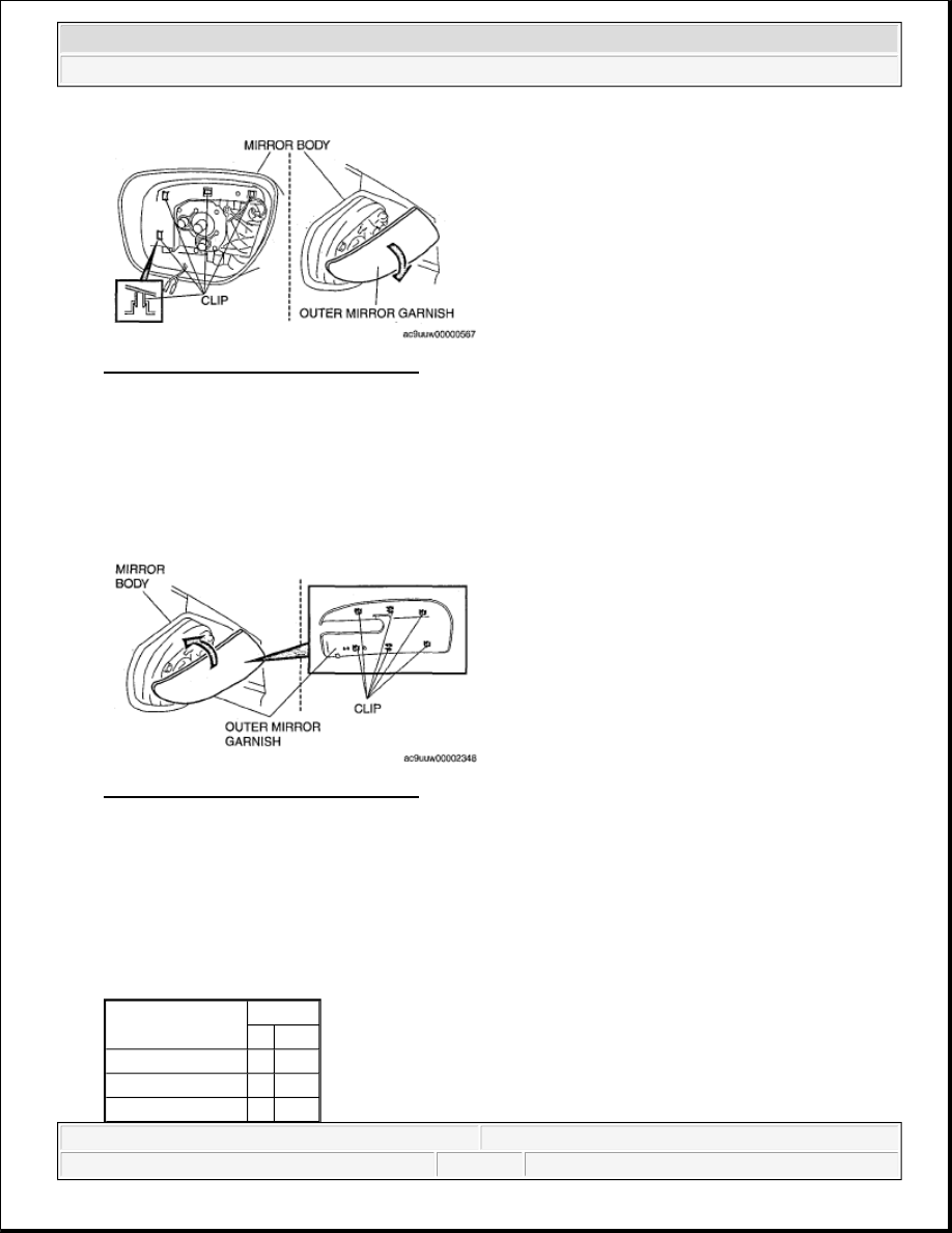
Fig. 66: View Of Outer Mirror Garnish 
Courtesy of MAZDA MOTORS CORP. 

OUTER MIRROR GARNISH INSTALLATION 

1. Position the outer mirror garnish against the mirror body in the direction of the arrow shown in the figure, 

and insert the outer mirror garnish clips (6 locations) into the mirror body.  

2. Install the outer mirror garnish so that there are no gaps around the component. 

Fig. 67: View Of Outer Mirror Garnish 
Courtesy of MAZDA MOTORS CORP. 

POWER OUTER MIRROR INSPECTION 

1. Apply battery positive voltage to the power outer mirror terminals and inspect the operation of the power 

outer mirror. 

If not as specified, replace the power outer mirror.  

MIRROR OPERATION CHART 

Mirror operation

terminal
B+ GND

Up

A

B

Down

B

A

Left

C

B


2008 Mazda CX-9 Grand Touring 

2008 BODY & ACCESSORIES Glass/Windows/Mirrors - Mazda CX-9


Microsoft 


Sunday, November 15, 2009 10:36:17 AM

Page 46 

© 2005 Mitchell Repair Information Company, LLC. 

Fig. 68: Power Outer Mirror - Circuit Diagram 
Courtesy of MAZDA MOTORS CORP. 

2. Inspect for continuity between the power outer mirror heater terminals. 

If not as specified, replace the power outer mirror. 

Fig. 69: Power Outer Mirror Heater Continuity Chart 
Courtesy of MAZDA MOTORS CORP. 

Fig. 70: Power Outer Mirror Heater - Circuit Diagram 
Courtesy of MAZDA MOTORS CORP. 

3. Verify that the continuity is as indicated in the table. 

If not as indicated, replace the power outer mirror. 

Right

B

C


2008 Mazda CX-9 Grand Touring 

2008 BODY & ACCESSORIES Glass/Windows/Mirrors - Mazda CX-9


Microsoft 


Sunday, November 15, 2009 10:36:17 AM

Page 47 

© 2005 Mitchell Repair Information Company, LLC. 

Fig. 71: BSM Indicator Light Connector Continuity Chart 
Courtesy of MAZDA MOTORS CORP. 

Fig. 72: BSM Indicator Light Connector - Circuit Diagram 
Courtesy of MAZDA MOTORS CORP. 

BLIND SPOT MONITORING (BSM) INDICATOR LIGHT INSPECTION 

1. Apply battery voltage to BSM indicator light terminal A, and connect terminal B to ground.  

2. Verify that the BSM indicator light illuminates. 

If there is any malfunction, replace the outer mirror glass. 


2008 Mazda CX-9 Grand Touring 

2008 BODY & ACCESSORIES Glass/Windows/Mirrors - Mazda CX-9


Microsoft 


Sunday, November 15, 2009 10:36:17 AM

Page 48 

© 2005 Mitchell Repair Information Company, LLC. 

Fig. 73: Blind Spot Monitoring Indicator Light - Circuit Diagram 
Courtesy of MAZDA MOTORS CORP. 

POWER OUTER MIRROR SWITCH REMOVAL/INSTALLATION 

POWER OUTER MIRROR SWITCH INSPECTION 

1. Inspect for continuity between the power outer mirror switch terminals using an ohmmeter. 

If not as indicated in the table, replace the power outer mirror switch. 

Fig. 74: Power Outer Mirror Switch Continuity Chart 
Courtesy of MAZDA MOTORS CORP.

NOTE:

The power outer mirror switch is integrated with the power window main 
switch.(See POWER WINDOW MAIN SWITCH REMOVAL/INSTALLATION)  


2008 Mazda CX-9 Grand Touring 

2008 BODY & ACCESSORIES Glass/Windows/Mirrors - Mazda CX-9


Microsoft 


Sunday, November 15, 2009 10:36:17 AM

Page 49 

© 2005 Mitchell Repair Information Company, LLC. 


Content   ..  605  606  607  608   ..