Mazda CX-9 Grand Touring. Manual - part 504


  Index      Mazda     Mazda CX-9 Grand Touring - service repair manual 2008 year


Search            


Content   ..  502  503  504  505   ..


Mazda CX-9 Grand Touring. Manual - part 504


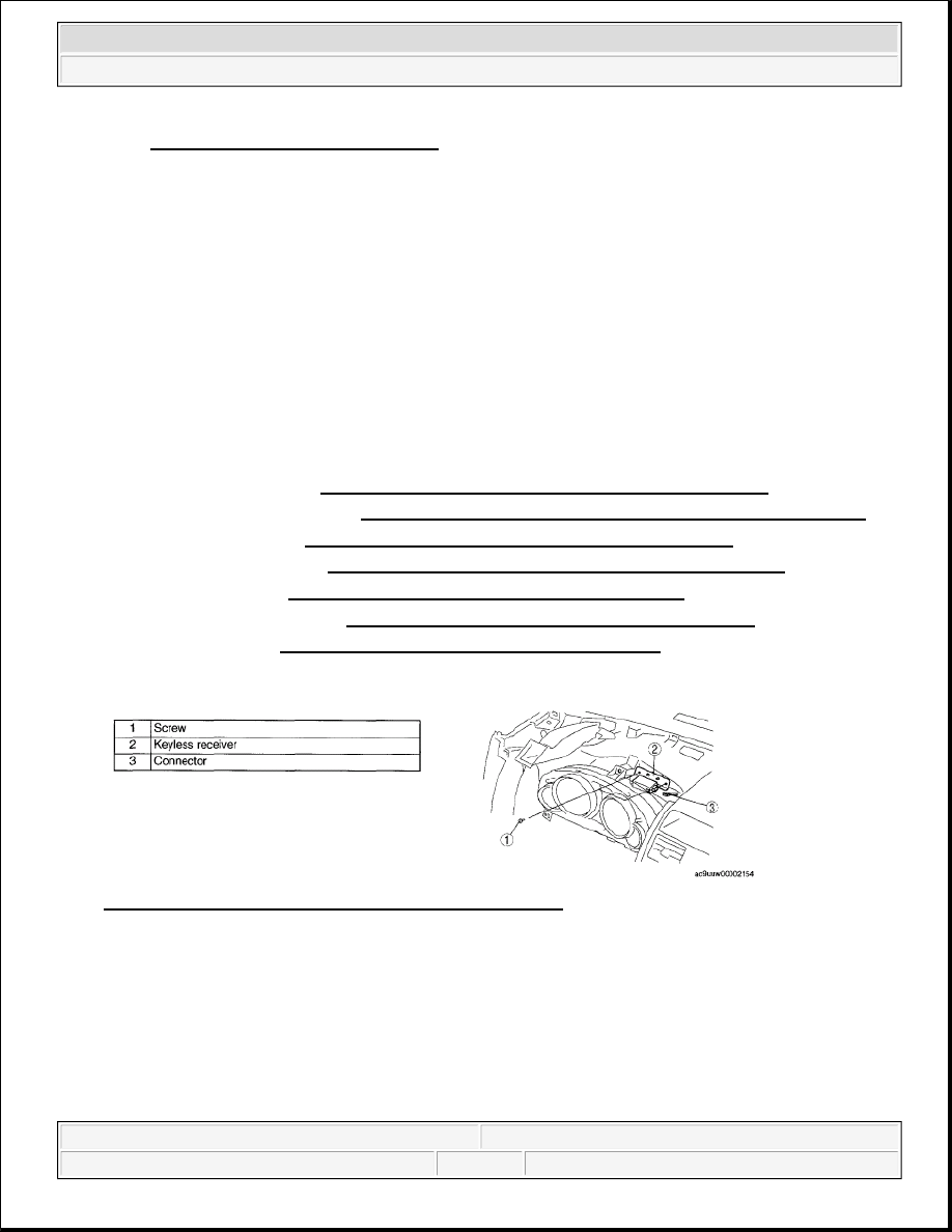
Fig. 63: Identifying DLC-2 Location
Courtesy of MAZDA MOTORS CORP.
 

4. Select the item name, and than select either "OFF/ON". 

Items  

Automatic Locks  

Answer Back Buzzer  

Card Key Battery Low Warning  

KEYLESS RECEIVER REMOVAL/INSTALLATION 

1. Disconnect the negative battery cable.  

2. Remove the following parts: 

1. Decoration panel (See DECORATION PANEL REMOVAL/INSTALLATION .)  

2. Front console box mat (See FRONT CONSOLE BOX MAT REMOVAL/INSTALLATION .)  

3. Indicator panel (See INDICATOR PANEL REMOVAL/INSTALLATION .)  

4. Front console box (See FRONT CONSOLE BOX REMOVAL/INSTALLATION .)  

5. Center panel (See CENTER PANEL REMOVAL/INSTALLATION .)  

6. Upper column cover (See COLUMN COVER REMOVAL/INSTALLATION .)  

7. Meter hood (See METER HOOD REMOVAL/INSTALLATION .)  

3. Remove in the order indicated in the table. 

Fig. 64: Identifying Keyless Receiver, Connector & Screw 
Courtesy of MAZDA MOTORS CORP. 

4. Install in the reverse order of removal.  

KEYLESS RECEIVER INSPECTION [ADVANCED KEYLESS SYSTEM] 

1. Measure the voltage at the auto light/wiper control module terminals as indicated below.  

TERMINAL VOLTAGE TABLE (REFERENCE) 


2008 Mazda CX-9 Grand Touring 

2008 BODY & ACCESSORIES Security and Locks - Mazda CX-9


Microsoft 


Sunday, November 15, 2009 10:47:58 AM

Page 43 

© 2005 Mitchell Repair Information Company, LLC. 

Fig. 65: Identifying Keyless Receiver Connector Terminals 
Courtesy of MAZDA MOTORS CORP. 

CONNECTOR TERMINALS REFERENCE 

KEYLESS RECEIVER INSPECTION [KEYLESS ENTRY SYSTEM] 

1. Measure the voltage at the auto light/wiper control module terminals as indicated below.  

TERMINAL VOLTAGE TABLE (REFERENCE) 

Terminal

Signal name

Connected 

to

Measured condition

Voltage 

(V)

Inspection item

(s)

A

Power supply

Keyless 
control 
module

Under any condition

B+

Keyless 
control 
module  

Related 
wiring 
harnesses  

C

Serial 
communication

Keyless 
control 
module

Because this terminal is for 
communication, good/no good 
judgment by terminal voltage is 
not possible.

-

Keyless 
control 
module  

Related 
wiring 
harnesses  

E

GND

Body ground Under any condition.

1.0 or 

less

Related wiring 
harnesses


2008 Mazda CX-9 Grand Touring 

2008 BODY & ACCESSORIES Security and Locks - Mazda CX-9


Microsoft 


Sunday, November 15, 2009 10:47:58 AM

Page 44 

© 2005 Mitchell Repair Information Company, LLC. 

Fig. 66: Identifying Keyless Receiver Connector Terminals 
Courtesy of MAZDA MOTORS CORP. 

CONNECTOR TERMINALS REFERENCE 

KEYLESS ANTENNA REMOVAL/INSTALLATION [ADVANCED KEYLESS 
SYSTEM] 

EXTERIOR, LF/RF 

1. Disconnect the negative battery cable.  

2. Remove the inner garnish. (See INNER GARNISH REMOVAL/INSTALLATION .)  

3. Remove the front door trim. (See FRONT DOOR TRIM REMOVAL/INSTALLATION .)  

4. Remove the screws.  

5. Disconnect the connector, then remove the keyless antenna.  

6. Install in the reverse order of removal. 

Terminal Signal name

Connected to

Measured condition

Voltage 

(V)

Inspection item(s)

A

Power supply

BCM

Under any condition

B+

BCM  

Related wiring 
harnesses  

B

IG1

ENG.IGA7.5 
A fuse

Ignition switch is at ON 
position

B+

ENG.IGA7.5 
A fuse  

Related wiring 
harnesses  

Ignition switch is at LOCK or 
ACC position

1.0 or 
less

D

Serial 
communication

BCM

Because this terminal is for 
communication, good/no good 
judgment by terminal voltage 
is not possible.

-

BCM  

Related wiring 
harnesses  

E

GND

Body ground Under any condition.

1.0 or 

less

Related wiring 
harnesses


2008 Mazda CX-9 Grand Touring 

2008 BODY & ACCESSORIES Security and Locks - Mazda CX-9


Microsoft 


Sunday, November 15, 2009 10:47:58 AM

Page 45 

© 2005 Mitchell Repair Information Company, LLC. 

Fig. 67: Identifying Keyless Antenna & Connector With Screw (Exterior, LF/RF) 
Courtesy of MAZDA MOTORS CORP. 

EXTERIOR, REAR 

1. Disconnect the negative battery cable.  

2. Remove the screws.  

3. Disconnect the connector, then remove the keyless antenna.  

4. Install in the reverse order of removal. 

Fig. 68: Identifying Keyless Antenna, Connector With Screw & Torque Specifications (Exterior, 
Rear)
 
Courtesy of MAZDA MOTORS CORP. 

INTERIOR, FRONT 

Center 

1. Disconnect the negative battery cable.  

2. Remove the decoration panel. (See DECORATION PANEL REMOVAL/INSTALLATION .)  

3. Remove the front console box mat. (See FRONT CONSOLE BOX MAT 

REMOVAL/INSTALLATION .)  

4. Remove the indicator panel. (See INDICATOR PANEL REMOVAL/INSTALLATION .)  

5. Remove the front console box. (See FRONT CONSOLE BOX REMOVAL/INSTALLATION .) 


2008 Mazda CX-9 Grand Touring 

2008 BODY & ACCESSORIES Security and Locks - Mazda CX-9


Microsoft 


Sunday, November 15, 2009 10:47:58 AM

Page 46 

© 2005 Mitchell Repair Information Company, LLC. 


Content   ..  502  503  504  505   ..