Mazda CX-9 Grand Touring. Manual - part 384


  Index      Mazda     Mazda CX-9 Grand Touring - service repair manual 2008 year


Search            


Content   ..  382  383  384  385   ..


Mazda CX-9 Grand Touring. Manual - part 384


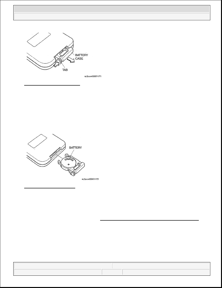
Fig. 57: View Of Battery Case 
Courtesy of MAZDA MOTORS CORP. 

3. Insert a new battery (CR2023) with the positive pole (+) facing up. 

Used battery  

Lithium battery CR2023  

4. Slide the battery case back into the remote controller until the tab clicks into place. 

Fig. 58: Identifying Battery 
Courtesy of MAZDA MOTORS CORP. 

AUXILIARY TERMINAL UNIT REMOVAL/INSTALLATION 

1. Disconnect the negative battery cable.  

2. Remove auxiliary terminal unit panel. (See TRUNK SIDE TRIM REMOVAL/INSTALLATION .)  

3. Remove in the order indicated in the table. 


2008 Mazda CX-9 Grand Touring 

2008 BODY & ACCESSORIES Entertainment - Mazda CX-9


Microsoft 


Sunday, November 15, 2009 10:47:06 AM

Page 33 

© 2005 Mitchell Repair Information Company, LLC. 

Fig. 59: Identifying Auxiliary Terminal Unit Screws 
Courtesy of MAZDA MOTORS CORP. 

4. Install in the reverse order of removal.  

POWER SUPPLY SOCKET REMOVAL/INSTALLATION 

1. Disconnect the negative battery cable.  

2. Remove auxiliary terminal unit panel. (See TRUNK SIDE TRIM REMOVAL/INSTALLATION .)  

3. Press the tabs, pull the power supply socket outward, and then remove it.  

4. Install in the reverse order of removal. 

Fig. 60: View Of Power Supply Socket 
Courtesy of MAZDA MOTORS CORP. 

INVERTER REMOVAL/INSTALLATION 

1. Disconnect the negative battery cable.  

2. Remove the following parts: 

1. Trunk box (See TRUNK BOX REMOVAL/INSTALLATION .)  

2. Seat side box (See SEAT SIDE BOX REMOVAL/INSTALLATION .)  

3. Trunk end trim (See TRUNK END TRIM REMOVAL/INSTALLATION .)  

4. Third-row seat (See THIRD-ROW SEAT REMOVAL/INSTALLATION .)  

5. Rear scuff plate inner (LH) (See REAR SCUFF PLATE REMOVAL/INSTALLATION .) 


2008 Mazda CX-9 Grand Touring 

2008 BODY & ACCESSORIES Entertainment - Mazda CX-9


Microsoft 


Sunday, November 15, 2009 10:47:06 AM

Page 34 

© 2005 Mitchell Repair Information Company, LLC. 

6. Third-row seat belt lower anchor installation bolt (LH) (See THIRD-ROW SEAT BELT 

REMOVAL/INSTALLATION .)  

7. Trunk side trim (Driver side) (See TRUNK SIDE TRIM REMOVAL/INSTALLATION .)  

3. Remove in the order indicated in the table. 

Fig. 61: Identifying Inverter Components & Torque Specifications 
Courtesy of MAZDA MOTORS CORP. 

4. Install in the reverse order of removal.  

INVERTER INSPECTION 

1. Measure the voltage at each terminal. 

If the voltage is not as specified in the Terminal Voltage Table, inspect the parts under "inspection 
item(s)" and related wiring harnesses.  

2. Disconnect the negative battery cable.  

3. If the system does not work properly even though the inspection items or related wiring harnesses do not 

have any malfunction, replace the inverter. 

WARNING:

The AC voltage is extremely high voltage. Be careful when 
measuring the voltage.  


2008 Mazda CX-9 Grand Touring 

2008 BODY & ACCESSORIES Entertainment - Mazda CX-9


Microsoft 


Sunday, November 15, 2009 10:47:06 AM

Page 35 

© 2005 Mitchell Repair Information Company, LLC. 

Fig. 62: Identifying Inverter Unit Connector Terminals
Courtesy of MAZDA MOTORS CORP.
 

TERMINAL VOLTAGE TABLE 

VOLTAGE SPECIFICATION 

REAR MOUNT CAMERA REMOVAL/INSTALLATION 

1. Remove the liftgate upper trim. (See LIFTGATE UPPER TRIM REMOVAL/INSTALLATION .)  

2. Remove the liftgate side trim. (See LIFTGATE SIDE TRIM REMOVAL/INSTALLATION .)  

3. Remove the liftgate lower trim. (See LIFTGATE LOWER TRIM REMOVAL/INSTALLATION .)  

4. Remove the rear finisher. (See REAR FINISHER REMOVAL/INSTALLATION .)  

5. Remove in the order indicated in the table. 

Fig. 63: Identifying Rear Mount Camera Screws 
Courtesy of MAZDA MOTORS CORP.

Terminal

Signal 

name

Connected to

Measured condition

Voltage (V)/ 

Continuity

Inspection item (s)

A, B

AC power 

supply 

output

Power supply 

socket (AC 115 V)

Ignition switch is at 
ACC or ON position

AC 103-5-

126.5

Power supply 
socket (AC 
115V)  

Related wiring 
harnesses  

Ignition switch is at 

LOCK position

1.0 or less

E

ACC

MIRROR 7.5 A 

fuse

Ignition switch is at 
ACC or ON position

B+

MIRROR 7.5 A 
fuse  

Related wiring 
harnesses  

Ignition switch is at 

LOCK position

1.0 or less

M

Power 

supply

AC PWR 15 A 

fuse

Under any condition

B+

AC PWR 15 A 
fuse  

Related wiring 
harnesses  

N

GND

Body ground

Under any condition

1.0 or less

Related wiring 
harnesses  


2008 Mazda CX-9 Grand Touring 

2008 BODY & ACCESSORIES Entertainment - Mazda CX-9


Microsoft 


Sunday, November 15, 2009 10:47:06 AM

Page 36 

© 2005 Mitchell Repair Information Company, LLC. 


Content   ..  382  383  384  385   ..