Mazda CX-9 Grand Touring. Manual - part 210


  Index      Mazda     Mazda CX-9 Grand Touring - service repair manual 2008 year


Search            


Content   ..  208  209  210  211   ..


Mazda CX-9 Grand Touring. Manual - part 210


Courtesy of MAZDA MOTORS CORP.

CIRCUIT OPEN/SHORT INSPECTION 

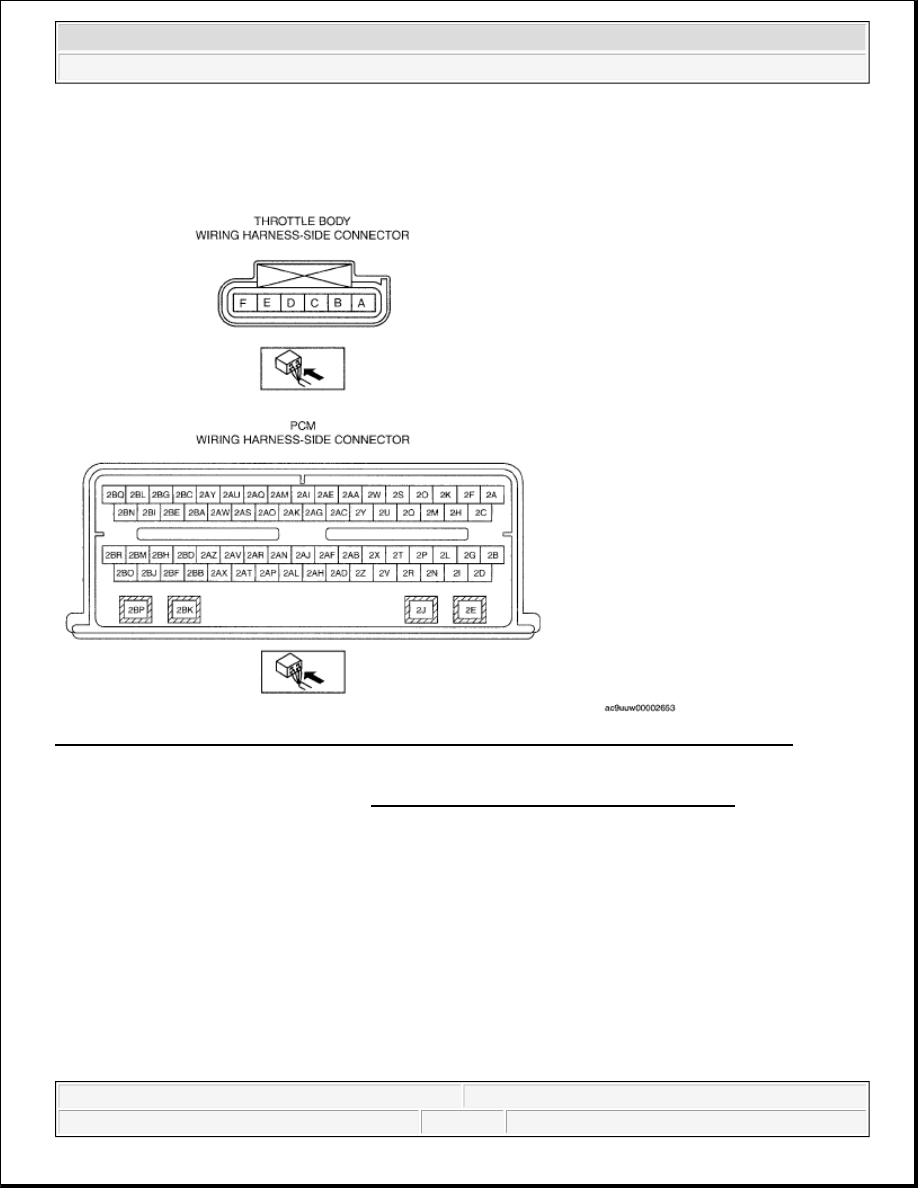
Fig. 17: Throttle Body Wiring Harness Side Connector & PCM Wiring Harness Side-Connector 
Courtesy of MAZDA MOTORS CORP. 

1. Disconnect the PCM connector. (See PCM REMOVAL/INSTALLATION [MZI-3.7].  

2. Inspect the following wiring harnesses for open or short circuit. (Continuity inspection)  

Open circuit 

If there is no continuity, there is an open circuit. Repair or replace the wiring harness. 

Throttle body terminal C and PCM terminal 2AD  

Throttle body terminal D and PCM terminal 2D  

Throttle body terminal E and PCM terminal 2AH  

Throttle body terminal F and PCM terminal 2Z  

Short circuit 


2008 Mazda CX-9 Grand Touring 

2008 ENGINE Control System (MZI-3.7) - Mazda CX-9


Microsoft 


Sunday, November 15, 2009 10:07:19 AM

Page 19 

© 2005 Mitchell Repair Information Company, LLC. 

If there is continuity, there is a short circuit. Repair or replace the wiring harness. 

Throttle body terminal C and power supply  

Throttle body terminal C and body ground  

Throttle body terminal D and body ground  

Throttle body terminal E and power supply  

Throttle body terminal F and body ground  

Throttle body terminal F and power supply  

ACCELERATOR PEDAL POSITION (APP) SENSOR INSPECTION [MZI-3.7] 

VOLTAGE INSPECTION 

1. Turn the ignition switch to the ON position (Engine OFF).  

2. Verify that the PCM terminal 1 AC, 1 AG and 1 AK change smoothly while throttle valve is gradually 

opened. 

If as verified, go to next step.  

If not as verified, perform the "Circuit Open/Short Inspection". 

If there is no open or short circuit, replace the throttle body.  

3. Verify that the PCM terminal 1 AC, 1 AG and 1 AK voltages are as shown in the following table. 

Fig. 18: Identifying PCM Wiring Harness Side-Connector 
Courtesy of MAZDA MOTORS CORP.

NOTE:

Before performing the following inspection, make sure to follow the 
procedure as indicated in the troubleshooting flowchart. (See HOW TO 
USE THIS MANUAL .)  


2008 Mazda CX-9 Grand Touring 

2008 ENGINE Control System (MZI-3.7) - Mazda CX-9


Microsoft 


Sunday, November 15, 2009 10:07:19 AM

Page 20 

© 2005 Mitchell Repair Information Company, LLC. 

If voltage is not as following table, perform the "Circuit Open/Short Inspection". 

If there is no open or short circuit, replace accelerator pedal. (See ACCELERATOR 
PEDAL REMOVAL/INSTALLATION [MZI-3.7]
 .)  

APP sensor output voltage  

APP SENSOR OUTPUT VOLTAGE SPECIFICATION CHART 

CIRCUIT OPEN/SHORT INSPECTION 

Fig. 19: Identifying Accelerator Pedal Position Sensor & PCM Wiring Harness Side Connector 
Courtesy of MAZDA MOTORS CORP. 

1. Disconnect the PCM connector. (See PCM REMOVAL/INSTALLATION [MZI-3.7].  

2. Inspect the following wiring harnesses for open or short circuit. (Continuity inspection)  

Condition

PCM terminal 1AK (APP 

sensor No.1)

PCM terminal 1AG (APP 

sensor No.2)

PCM terminal 1 AC 

(APP sensor No.3)

Accelerator pedal 
released

Approx. 4.1 V

Approx. 1.5 V

Approx. 0.1 V

Accelerator pedal 
depressed

Approx. 1.0 V

Approx. 3.9 V

Approx. 3.3 V


2008 Mazda CX-9 Grand Touring 

2008 ENGINE Control System (MZI-3.7) - Mazda CX-9


Microsoft 


Sunday, November 15, 2009 10:07:19 AM

Page 21 

© 2005 Mitchell Repair Information Company, LLC. 

Open circuit 

If there is no continuity, there is an open circuit. Repair or replace the wiring harness. 

APP sensor terminal B and PCM terminal 1 AC  

APP sensor terminal C and PCM terminal 1AH  

APP sensor terminal D and PCM terminal 1Y  

APP sensor terminal E and PCM terminal 1AK  

APP sensor terminal F and PCM terminal 1BA  

APP sensor terminal G and PCM terminal 1AD  

Short circuit 

If there is continuity, there is a short circuit. Repair or replace the wiring harness. 

APP sensor terminal B and body ground  

APP sensor terminal B and power supply  

APP sensor terminal C and power supply  

APP sensor terminal D and body ground  

APP sensor terminal E and body ground  

APP sensor terminal E and power supply  

APP sensor terminal F and body ground  

APP sensor terminal G and power supply  

CRANKSHAFT POSITION (CKP) SENSOR REMOVAL/INSTALLATION [MZI-
3.7] 

NOTE:

Disconnect the connector after the CKP sensor is removed to prevent the 
CKP sensor from falling off.  

The bolt and sensor are integrated and cannot be pulled out.  

When removing the CKP sensor, be careful not to drop the tool.  

The bolt and sensor must be pulled in different directions. Pull them as 
indicated in the figure. 

Fig. 20: Identifying CKP Sensor 


2008 Mazda CX-9 Grand Touring 

2008 ENGINE Control System (MZI-3.7) - Mazda CX-9


Microsoft 


Sunday, November 15, 2009 10:07:19 AM

Page 22 

© 2005 Mitchell Repair Information Company, LLC. 


Content   ..  208  209  210  211   ..