Mazda CX-9 Grand Touring. Manual - part 208
VOLTAGE SENSOR SPECIFICATION CHART
PCM CONFIGURATION [MZI-3.7]
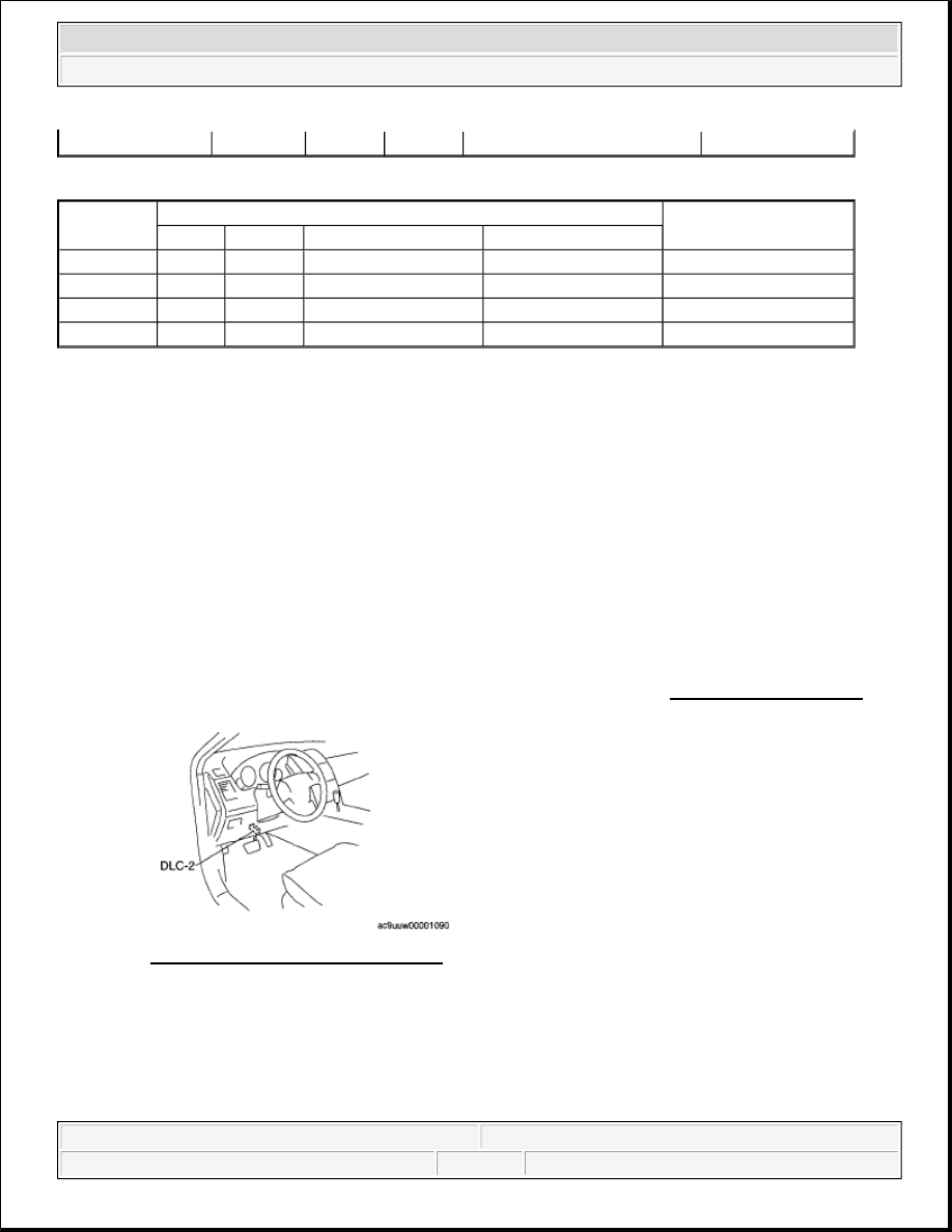
1. Connect the M-MDS to DLC-2.
2. After the vehicle is identified, select the following items from the initialization screen of the M-MDS.
When using the IDS (laptop PC)
1. Select the "Module Programming".
3. Then, select the "Programmable Module Installation", "PCM" from the screen menu.
4. Select "PCM" and perform procedures according to directions on the M-MDS screen.
5. Retrieve DTCs by the M-MDS, then verify that there is no DTC present.
If a DTC(s) is detected, perform the applicable DTC inspection. (See DTC TABLE [MZI-3.7] .)
Fig. 8: Identifying DLC-2 Connector
Courtesy of MAZDA MOTORS CORP.
POWER STEERING PRESSURE (PSP) SWITCH INSPECTION [MZI-3.7]
CONTINUITY INSPECTION
1. Disconnect the PSP switch connector.
VCTADVERR2
0
0.06
-0.43
0
DEG
Other
Measured/PID Values
Units Measured/PID
KOEO Hot Idle
48 KM/H (30MPH)
89 KM/H (55MPH)
ETCVREF
5
5
5
5
DCV
VREF
5
5
5
5
DCV
VPWR
VBAT
VBAT
VBAT
VBAT
DCV
KAPWR
VBAT
VBAT
VBAT
VBAT
DCV
NOTE:
Use the IDS (laptop PC) because the PDS (Pocket PC) does not support
the PCM CONFIGURATION.
2008 Mazda CX-9 Grand Touring
2008 ENGINE Control System (MZI-3.7) - Mazda CX-9
Microsoft
Sunday, November 15, 2009 10:07:19 AM
Page 11
© 2005 Mitchell Repair Information Company, LLC.