Mazda RX-8. Manual - part 30


  Index      Mazda     Mazda RX-8 - service repair manual 2004-2006 year


Search            


Content   ..  28  29  30 


Mazda RX-8. Manual - part 30


ENTERTAINMENT 

09–20–9

09–20

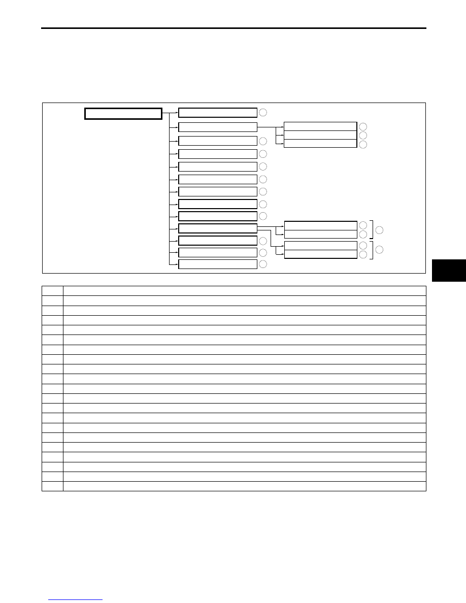
Destination Setting Function
Outline

The following instructions explain how destinations can be chosen and set.

Note

A destination can be set to where the crosshair cursor indicates by selecting the Destination option of the 
scroll map mode pop-menu.

.

End Of Sie

Intersection

Coordinates

Select from Map

Point of Interest

Previous Destination

Memory Point

Home

Preset Destination

Freeway On/Off Ramp

Change

Phone number

Destination top menu

Address

Name
Category
City

Emergency

Police station
Hospital

Nearby Police station
Nearby Hospital

1

9

8

7

5

4

3

10

11

6

2

14

13

12

19

18

17

15

16

20

E6U920ZS5199

No.

Contents

1

Sets destination by inputting address.

2

Sets destination by inputting POI name.

3

Sets destination by selecting POI category, inputting target name and selecting POI.

4

Sets destination by inputting city name and selecting POI.

5

Sets destination by moving the crosshair cursor to the destination when in scroll map mode.

6

Sets destination from a list of points stored by the user.

7

Sets destination from a list of recent destinations.

8

Sets destination by selecting intersection name.

9

Sets destination by inputting coordinates.

10

Sets destination to home.

11

Sets destination to preset destination point.

12

Sets destination to police station.

13

Sets destination to hospital.

14

Sets destination to nearby police station.

15

Sets destination to nearby hospital.

16

Vehicle is stopped.

17

Vehicle is running.

18

Sets destination by selecting Freeway On Ramp/Off Ramp

19

Sets destination by inputting phone number.

20

Changes search area.

INSTRUMENTATION/DRIVER INFO. 

09–22–1

09–22

09–22

INSTRUMENTATION/DRIVER INFO.

INSTRUMENT CLUSTER OUTLINE . . . .  09–22–1
INSTRUMENT CLUSTER 

SPECIFICATIONS . . . . . . . . . . . . . . . . .  09–22–2

INSTRUMENT CLUSTER 

STRUCTURAL VIEW . . . . . . . . . . . . . . . 09–22–4

Warning And Indicator Light  . . . . . . . . . 09–22–4

End of Toc

INSTRUMENT CLUSTER OUTLINE

EHU092255430101

Following indicator lights have been added.

Keyless indicator light (with advanced keyless system)

Keyless warning lightt (with advanced keyless system)

Following alarm have been modified.

Advanced keyless system warning alarm (with advanced keyless system)

Key reminder warning alarm

Seat belt warning alarm

End Of Sie

INSTRUMENTATION/DRIVER INFO. 

09–22–2

INSTRUMENT CLUSTER SPECIFICATIONS

EHU092255430102

Item

Specification

Speedometer

Meter type

LCD

Indication range

 (mph {km/h})

0—186 {0—299}

Input signal communication system 

CAN system

Input signal source

ABS HU/CM (with ABS)

DSC HU/CM (with DSC)

Rated voltage 

(V)

DC 12

Tachometer

Meter type

Stepping motor type

Indication range

(rpm)

0—9,000 (13B-MSP (Standard Power))

0—10,000 (13B-MSP (High Power))

Red zone

(rpm)

7,500—9,000 (13B-MSP (Standard Power))

9,000—10,000 (13B-MSP (High Power))

Input signal communication system 

CAN system

Input signal source

PCM

Rated voltage 

(V)

DC 12

Fuel gauge

Meter type

Stepping motor type (Reset-to-zero type)

Input signal communication system 

Conventional communication system

Input signal source

Fuel gauge sender unit

Rated voltage 

(V)

DC 12

Water 
temperature 
gauge

Meter type

Stepping motor type (Medium range stabilized 

type)

Input signal communication system 

CAN system

Input signal source

PCM

Rated voltage 

(V)

DC 12

Odometer/
Tripmeter

Display

LCD

Indication digits

Odometer: 6 digits, Tripmeter: 4 digits

Input signal communication system 

CAN system

Input signal source

PCM

Rated voltage 

(V)

DC 12

Clock accuracy (Reference value)*

(s/day)

-1.5—1.5


Content   ..  28  29  30