Mazda RX-8. Manual - part 18


  Index      Mazda     Mazda RX-8 - service repair manual 2004-2006 year


Search            


Content   ..  16  17  18  19   ..


Mazda RX-8. Manual - part 18


AUTOMATIC TRANSMISSION [SJ6A-EL]

05–13–31

05–13

Shift control in active adaptive shift (AAS) mode

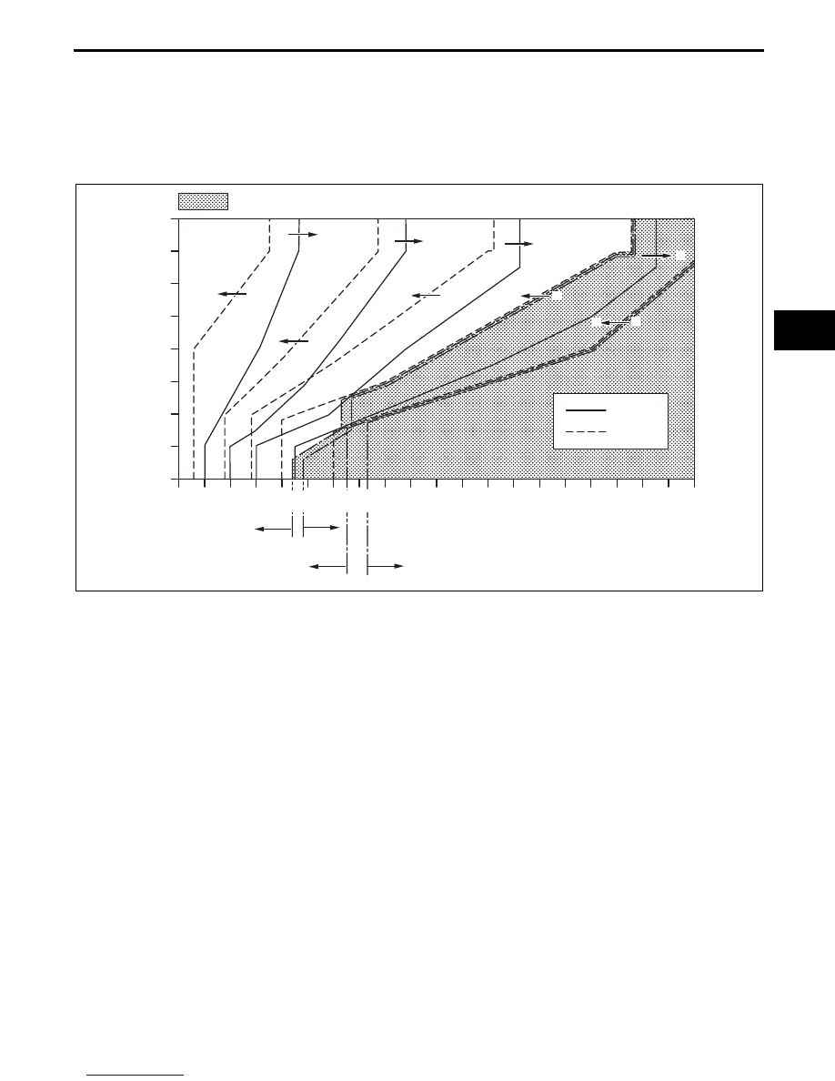
Shift control is performed according to the shift pattern in AAS mode.

When the driver releases the accelerator pedal fully and rapidly, the gear position is maintained at the position 
before accelerator pedal was released. Due to this, re-acceleration and vehicle control performance have been 
improved. If the accelerator pedal is released slowly, the gears shift up according to the shift pattern.

While cornering the vehicle, the gear position is maintained at the position before the vehicle was cornered to 
facilitate re-acceleration after the corner. The gears do not shift up if the accelerator pedal is depressed fully 
while cornering the vehicle.

Forced cancellation of active adaptive shift (AAS) mode

AAS mode is forcibly cancelled under the following conditions:

The vehicle speed in the cruise control system is reset.

The selector lever is shifted to M range while driving in D range.

Down Slope Mode

While the vehicle is being driven on a down slope, the TCM determines that the vehicle is being driven on a 
down slope based on the signals and output engine speed from the PCM, and switches the driving mode to the 
DOWN SLOPE MODE. Due to this, load to the brake is reduced.

Up Slope Mode

When the vehicle is climbing a slope, the TCM determines that the vehicle is being driven on an up slope based 
on the signals and output engine speed from the PCM, and switches the driving mode to the UP SLOPE 
MODE. Due to this, reduction in traction is prevented.

End Of Sie

0/8

1/8

2/8

3/8

4/8

5/8

6/8

7/8

8/8

TCC OPERATION AVAILABLE

VEHICLE SPEED  km/h {mph}

5GR
TCC OFF

6GR TCC OFF

6GR TCC ON

5GR
TCC ON

0

{0}

10

{6.2}

20

{12}

30

{19}

40

{25}

50

{31}

60

{37}

70

{43}

80

{50}

90

{56}

100

{62}

110

{68}

120

{74}

130

{81}

140

{87}

150

{93}

160

{99}

170

{105}

180

{112}

190

{118}

200

{124}

1

1

2

2

2

2

3

2

4

5

2

3

4

5

3

4

3

4

5

6

THR

O

TTLE OPENING

SHIFT UP

SHIFT DOWN

EHU513BS8008

AUTOMATIC TRANSMISSION [SJ6A-EL]

05–13–32

MANUAL MODE SHIFT CONTROL STRUCTURE [SJ6A-EL]

EHU051318901107

Features

The manual mode shift control is activated by moving the selector lever from the D to M range position (selector 
lever is shifted over toward driver side). 

Manual mode shift control with a manual shifting system allowing selection of gear positions by manual 
operation of the selector lever forward (–) and back (+) has been adopted. Moreover, engine braking for all 
gears in manual mode according to the gear ratio is available. 

Shifting between 1GR and 2GR when the vehicle is stopped is possible. Moreover, when shifting from the D 
to M range while driving, the same gear position is maintained.

Consecutive shifting in the M range has been adopted. When shifting down from M range 6GR or 5GR, one 
gear can be skipped over by rapidly tapping the selector lever two times in the down-shift (–) direction.

Specialized manual mode selector lever position and gear position indicator lights, built into the instrument 
cluster, have been adopted. The gear position indicator light displays the selected gear position while in manual 
mode.

The selector indicator light includes a selector lever position indicator that displays selector lever positions 
and, in M range, a gear position indicator light that displays gear positions.

Structure
System diagram

End Of Sie

PCM

TCM

TR SWITCH

TFT SENSOR

M RANGE SWITCH

UP SWITCH

DOWN SWITCH

GEAR POSITION INDICATOR LIGHT

SELECTOR INDICATOR LIGHT

AT WARNING LIGHT

ENGINE 

TRANSMISSION

SELECTOR LEVER COMPONENT

UP SWITCH

DOWN SWITCH

STEERING SHIFT SWITCH

INSTRUMENT CLUSTER

E5U513ZS5033

AUTOMATIC TRANSMISSION [SJ6A-EL]

05–13–33

05–13

MANUAL MODE SHIFT CONTROL OPERATION [SJ6A-EL]

EHU051318901108

Manual Mode Shift

When the selector lever is shifted over from the D to M range position, the M range switch in the selector lever 
component turns on, sending a manual mode command signal to the TCM which activates the manual mode 
shift control.

When in manual mode and the selector lever is operated in the back (+) direction, the up switch in the selector 
lever component is turned on and an up-shift command signal is input to the TCM. 

The TCM, triggered by the up-shift command signal, carries out shifting by outputting an operation signal to 
the shift control solenoid. 

Conversely, when the selector lever is operated in the forward (–) direction, the down switch in the selector lever 
component turns on, and a down-shift command signal is input to the TCM. 

The TCM, triggered by the down-shift command signal, carries out shifting by outputting an operation signal 
to the shift control solenoid if the vehicle speed is less than the set speed and the gear position is 2GR or 
above.

The up/down operation of the steering shift switch is the same as the manual operation of the selector lever.

The TCM utilizes a specialized M range automatic shift diagram. Due to this, restriction of manual shift demand 
and automatic control of downshifting is carried out, reducing load on the AT, preventing engine over-rev and 
ensuring drive stability.

Condition

Shift control

Note

1GR

2GR up-shift command, 

at low speed

To reduce load on the AT, upshifting is 
inhibited until vehicle reaches speed possible 
for upshifting

2GR

3GR up-shift command, 

at low speed

3GR

4GR up-shift command, 

at low speed

4GR

5GR up-shift command, 

at low speed

5GR

6GR up-shift command, 

at low speed

5GR

6GR up-shift command, 

low ECT

To rapid engine warming-up, upshifting to 
6GR is inhibited

6GR

5GR down-shift 

command, above set speed

To prevent engine over-rev, downshifting is 
inhibited until vehicle reaches speed possible 
for downshifting

Gear position indicator light flash to 
alert driver

5GR

4GR down-shift 

command, above set speed

4GR

3GR down-shift 

command, above set speed

3GR

2GR down-shift 

command, above set speed

2GR

1GR down-shift 

command, above set speed

In 6GR deceleration, speed 
goes below coast-down set 
speed (deceleration down- 
shift)

To assure drive stability, automatically 
downshifts from 6GR to 5GR

In 5GR deceleration, speed 
goes below coast-down set 
speed (deceleration down- 
shift)

To assure drive stability, automatically 
downshifts from 5GR to 4GR

In 4GR deceleration, speed 
goes below coast-down set 
speed (deceleration down- 
shift)

To assure drive stability, automatically 
downshifts from 4GR to 3GR

In 3GR deceleration, speed 
goes below coast-down set 
speed (deceleration down- 
shift)

To assure drive stability, automatically 
downshifts from 3GR to 2GR

In 2GR deceleration, speed 
goes below coast-down set 
speed (deceleration down- 
shift)

To assure drive stability, automatically 
downshifts from 2GR to 1GR

AUTOMATIC TRANSMISSION [SJ6A-EL]

05–13–34

Shift Diagram

End Of Sie

AT WARNING LIGHT FUNCTION [SJ6A-EL]

EHU051321101107

The AT warning light illuminates to alert the driver of a malfunction in the automatic transmission.

End Of Sie

Wide open throttle at 175—
210 km/h {109—130 mph} in 
6GR

To improve acceleration performance, 6GR 
to 5GR kickdown occurs

Wide open throttle at 40—174 
km/h {25—108 mph} in 5GR

To improve acceleration performance, 5GR 
to 4GR kickdown occurs

Condition

Shift control

Note

4

5

5

6

6

3

4

1

2

2

1

4

3

5

4

3

2

4

5

VEHICLE SPEED  km/h {mph}

TCC OPERATION AVAILABLE

THR

O

TTLE OPENING

5GR                
TCC OPERATION 
OFF

5GR                
TCC OPERATION 
ON

6GR                
TCC OPERATION 
ON

6GR                
TCC OPERATION 
OFF

2

3

1

2

200

{124}

190

{118}

180

{112}

170

{105}

160

{99}

150

{93}

140 

{87}

130

{81}

120

{74}

110

{68}

90

{56}

100

{62}

80

{50}

70

{43}

50

{31}

60

{37}

30

{19}

40

{25}

10

{6.2}

20

{12}

0

{0}

8/8

7/8

6/8

5/8

4/8

3/8

2/8

1/8

0/8

4

5

5

2

3

3

4

DOWNSHIFTING IS INHIBITED UNTIL VEHICLE 
REACHES SPEED POSSIBLE FOR DOWNSHIFTING
WHEN DECELERATING BELOW SET VEHICLE SPEED, 
EXECUTES AUTOMATIC DOWNSHIFTING

UPSHIFTING IS INHIBITED UNTIL VEHICLE 
REACHES SPEED POSSIBLE FOR UPSHIFTING
WHEN WIDE OPEN THROTTELE, 
EXECUTES KICKDOWN

EHU513BS8004


Content   ..  16  17  18  19   ..