Mazda RX-8. Manual - part 17


  Index      Mazda     Mazda RX-8 - service repair manual 2004-2006 year


Search            


Content   ..  15  16  17  18   ..


Mazda RX-8. Manual - part 17


AUTOMATIC TRANSMISSION [SJ6A-EL]

05–13–27

05–13

SHIFT SOLENOID E OUTLINE [SJ6A-EL]

EHU051321101102

Shift solenoid E is directly equipped to the control valve body component.

Shift solenoid E turns on and off according to the control signals from the TCM, and switches the C4 clutch and 
the B1 brake.

End Of Sie

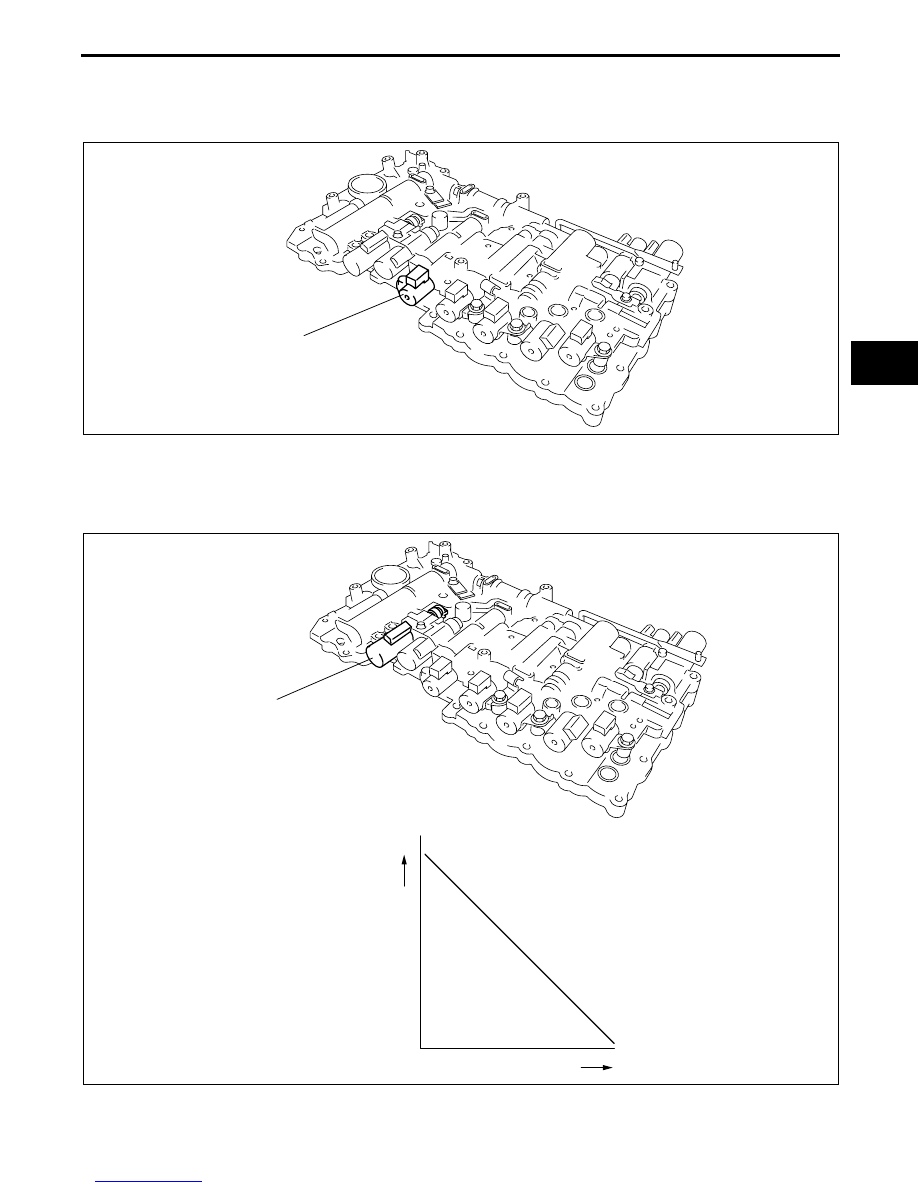
LINE PRESSURE CONTROL SOLENOID OUTLINE [SJ6A-EL]

EHU051321101103

Performs linear adjustment of the throttle pressure based on the control signals from the TCM, and controls the 
pressure which is applied to the clutches and brakes to adjust the line pressure and to reduce shift shock.

End Of Sie

SHIFT 
SOLENOID E

E5U513ZS5028

LINE PRESSURE 
CONTROL SOLENOID

INCREASES

INCREASES

CURRENT

GENERATED 
HYDRAULIC PRESSURE

E5U513ZS5029

AUTOMATIC TRANSMISSION [SJ6A-EL]

05–13–28

TORQUE CONVERTER CLUTCH (TCC) CONTROL SOLENOID OUTLINE [SJ6A-EL]

EHU051321101104

Adjusts the pressure of the TCC in the torque converter based on the control signals from the TCM.

End Of Sie

INCREASES

INCREASES

CURRENT

TCC CONTROL 
SOLENOID

GENERATED 
HYDRAULIC PRESSURE

E5U513ZS5030

AUTOMATIC TRANSMISSION [SJ6A-EL]

05–13–29

05–13

SHIFT SOLENOID F, G OUTLINE [SJ6A-EL]

EHU051321101105

By performing linear adjustment of the C3 clutch pressure and the B2 brake pressure based on the control 
signals from the TCM, the pressure which is applied to the C3 clutch and the B2 brake is directly controlled 
during shift changes from 5th to 6th gears.

End Of Sie

INCREASES

INCREASES

CURRENT

GENERATED 
HYDRAULIC PRESSURE

SHIFT 
SOLENOID G

SHIFT 
SOLENOID F

E5U513ZS5031

AUTOMATIC TRANSMISSION [SJ6A-EL]

05–13–30

COUPLER COMPONENT OUTLINE [SJ6A-EL]

EHU051321101106

The coupler component are installed on the transmission case as the grouped connectors of the TFT sensor 
and solenoids.

.

End Of Sie

SHIFT CONTROL OUTLINE [SJ6A-EL]

EHU051318901106

Based on the shift diagram, shift solenoids A, B, C, D, E, F, and G are controlled according to the vehicle speed 
and the throttle opening angle, and the shift control of the transmission is performed. 

When certain conditions are met, the TCM selects a shift mode suitable to the driving conditions and 
automatically switches to the mode to perform smooth shifting.

Active Adaptive Shift (AAS) Mode

When certain conditions are met, AAS mode is automatically selected from normal mode. In AAS mode, the 
shift point is set higher than the normal shift point so that high-engine speed, high-output conditions are 
available.

AAS mode is canceled when the vehicle speed remains constant (stable vehicle behavior).

Conditions for switching to active adaptive shift (AAS) mode

The accelerator pedal is depressed fully to accelerate rapidly while driving in D range.

Rapid acceleration or deceleration continues for a certain period of time while driving in D range.

LINE PRESSURE 
CONTROL SOLENOID

SHIFT 
SOLENOID E

SHIFT 
SOLENOID F

SHIFT 
SOLENOID D

SHIFT 
SOLENOID G

SHIFT 
SOLENOID A

SHIFT 
SOLENOID B

SHIFT 
SOLENOID C

TCC CONTROL 
SOLENOID

TFT SENSOR

A

B

H

J

L

N

D

F

G

E

C

I

K

M

O

E5U513ZS5032

Terminal 

No.

Signal

A

TFT sensor (–)

B

TFT sensor (+)

C

Shift solenoid G (–)

D

Shift solenoid G (+)

E

Shift solenoid F (–)

F

Shift solenoid F (+)

G

TCC control solenoid (–)

H

TCC control solenoid (+)

I

Line pressure control solenoid (–)

J

Line pressure control solenoid (+)

K

Shift solenoid E

L

Shift solenoid D

M

Shift solenoid C

N

Shift solenoid B

O

Shift solenoid A

Terminal 

No.

Signal


Content   ..  15  16  17  18   ..