Mazda RX7. Manual - part 76


  Index      Mazda     Mazda RX7 - service repair manual 1983 year


Search            


Content   ..  74  75  76  77   ..


Mazda RX7. Manual - part 76


HEATING SYSTEM TROUBLESHOOTING CAT. U, NO. 93-04

Article Text (p. 9)

1983 Mazda RX7

For www.iluvmyrx7.com    

Copyright © 1998 Mitchell Repair Information Company, LLC

Monday, August 27, 2001  06:36AM

Fig. 5:  Air Intake Selector (Type A and B)

Item 2 - Function Selector

This selector controls the direction of the airflow from the vents. On
initial start during cold or high humidity temperatures the selector
should be placed in the defrost position and the fan speed set to 3 or
4. After the front and side windows become clear the selector can be
switched to defrost/heat and then to heat only as necessary and the
fan speed reduced. If the front or side windows begin to fog again
while driving the selector should be reset to the defrost/heat or full
defrost and the fan speed adjusted as necessary. In addition to the
above, air-conditioning can be used in conjunction with the heating
system to control the humidity level in the vehicle while providing
heat.

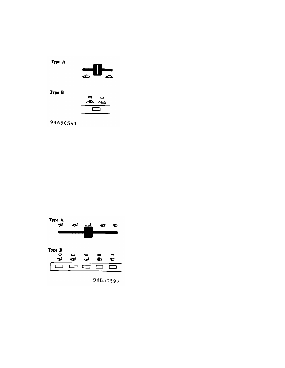
Fig. 6:  Function Selector (Type A and B)

Item 3 - Temperature Selector Lever

This lever controls air temperature by sliding the lever either   to
the right for hot or to the left for cold. On start up during cold
temperatures the selector should be set to the full heat position at
far right of the selectors travel. See Fig. 7.
As the interior of the vehicle reaches the desired temperature the
selector should be adjusted to the left towards the cold setting by
increments until the desired temperature is reached.

HEATING SYSTEM TROUBLESHOOTING CAT. U, NO. 93-04

Article Text (p. 10)

1983 Mazda RX7

For www.iluvmyrx7.com    

Copyright © 1998 Mitchell Repair Information Company, LLC

Monday, August 27, 2001  06:36AM

Fig. 7:  Temperature Selector (Type A and B)

Climate Control System

Shown in Fig. 8 is a typical climate control system. Detailed
descriptions of each function are found under the heading "Driving
Your Mazda" in the appropriate Owners Manual.

Fig. 8:  Climate Control System Layout

END OF ARTICLE

INOPERATIVE A/C - BLOWN FUSIBLE RECEIVER/DRYER PLUG CAT. 16, NO. 009/85

Article Text

1983 Mazda RX7

For www.iluvmyrx7.com    

Copyright © 1998 Mitchell Repair Information Company, LLC

Monday, August 27, 2001  06:36AM

ARTICLE BEGINNING

TECHNICAL SERVICE BULLETIN

APPLICATION

  1979-85 RX7

SUBJECT

  Inoperative A/C

REFERENCE

  Mazda Motors Corp., Service Bulletin, No. 16 009/85, September, 1985

CONDITION & CAUSE

Some 1979-85 RX7 vehicles may exhibit an inoperative air conditioning
system. This condition may be caused by a variety of factors blowing
the fusible plug on the receiver/drier.

REPAIR

1) If the fusible plug on the receiver/drier is blown, replace the
receiver/drier and evacuate the A/C system.
2) Check the tension of the compressor drive belt. With center span of
belt pushed with a force of 22 lbs. (10 kg), deflection should be
5/16-3/8" (8-10 mm). Ensure the fins on the condenser are not clogged
or restricted and clean as necessary.
3) Attach an air conditioning manifold to the suction and discharge
fittings. If the high pressure gauge shows excessive pressure, check
the fan drive clutch and replace as necessary.

END OF ARTICLE

POOR A/C COOLING - ADJUST A/C THERMOSTAT CAT. 16, NO. 006/85

Article Text

1983 Mazda RX7

For www.iluvmyrx7.com    

Copyright © 1998 Mitchell Repair Information Company, LLC

Monday, August 27, 2001  06:37AM

ARTICLE BEGINNING

TECHNICAL SERVICE BULLETIN

NIPPONDENSO AIR CONDITIONER

Models          RX-7 13B
Bulletin No.    006/85
Category        16
Date            5/17/85
Symptom         Poor Cooling

DESCRIPTION

   If the customer objects to the cooling performance of the air
conditioner on RX-7 13B vehicles, please follow the procedure
described below.

REPAIR PROCEDURE

   1. Check the air conditioning system for insufficient cooling
      according to the current Service Information. If no problem
      is found, proceed to Step 2.
   2. Remove the glove box and the under cover. See Fig. 1.

Fig. 1:  Removing Glove Box & Under Cover

   3. Remove the 2 screws securing the thermostat. Pull the thermostat
      approximately "1" away from the evaporator in order to provide
      access to the thermostat adjusting screw.

NOTE: Do not damage the capillary tube attached to the thermostat by
      excessive bending or twisting. See Fig. 2.


Content   ..  74  75  76  77   ..