Mazda RX7. Manual - part 60


  Index      Mazda     Mazda RX7 - service repair manual 1983 year


Search            


Content   ..  58  59  60  61   ..


Mazda RX7. Manual - part 60


DRIVE AXLE

Article Text (p. 2)

1983 Mazda RX7

For www.iluvmyrx7.com    

Copyright © 1998 Mitchell Repair Information Company, LLC

Sunday, August 26, 2001  06:34PM

         AXLE SHAFTS & BEARINGS

         Removal
         1) Raise and support vehicle. Remove wheel. Remove brake
drum and brake shoes. Disconnect and plug hydraulic line from wheel
cylinder. Disconnect parking brake cable.
         2) From inboard side of backing plate, remove 4 nuts from
axle housing through bolts. Pull drive axle, backing plate, bearing
housing (Pickups) and shims (if equipped) from axle housing with
drive axle puller (49 0223 630B). Remove oil seal from axle housing.
         3) On Pickup models, flatten locking tabs of lock washer.
Loosen lock nut with spanner wrench. Remove lock nut and washer.
         4) Using bearing pullers (49 8531 746 & 49 0259 747), remove
bearing and housing assembly from drive axle. Remove backing plate.
Remove bearing and oil seal from housing.

         Installation
         1) Install backing plate and spacer on shaft with chamfered
edge of spacer must face drive axle flange. Using bearing attachment,
(49 0259 748) press bearing onto shaft until seated. Press new
bearing collar onto shaft without any lubricant.

CAUTION: Do not press bearing and collar onto shaft at the same time.
         If bearing collar is installed with less than 2.7 tons
         pressure (2,451 kg), replace bearing collar.

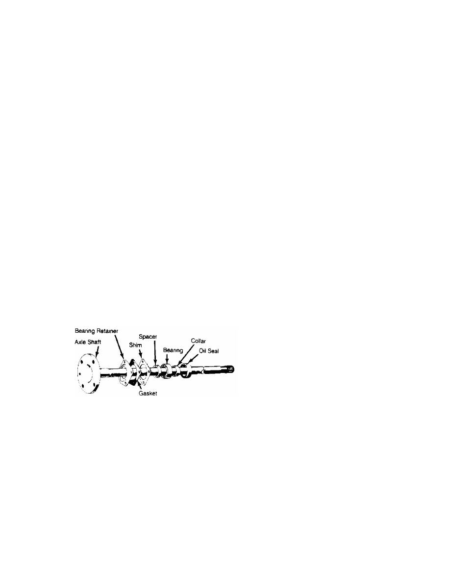
Fig. 2:  Exploded View of Axle Shaft Assembly
for All Models Except Pickups
Chamfered edge of spacer must face drive axle flange.

         2) Apply a light coat of grease to oil seal and install oil
seal in housing. Temporarily mount drive axle and backing plate on
axle housing with mounting nuts.
         3) Install dial indicator on backing plate and check drive
axle end play. End play should be .002-.006" (.05-.15 mm) on Pickups
and 0-.004" (0-.1 mm) on all other models.
         4) On Pickup models only, if both drive axles were removed,
the end play of each shaft must be measured separately. The end play
for first drive axle installed should be .026-.033" (.65-.85 mm).
         5) The end play for the second drive axle installed should
be set to normal end play clearance of .002-.006" (.05-.15 mm).
         6) After installing correct shim pack, install and tighten
all attaching bolts and nuts. Install brake shoes and drum. Connect
hydraulic lines to wheel cylinders, adjust brakes and bleed hydraulic

DRIVE AXLE

Article Text (p. 3)

1983 Mazda RX7

For www.iluvmyrx7.com    

Copyright © 1998 Mitchell Repair Information Company, LLC

Sunday, August 26, 2001  06:34PM

system.

Fig. 3:  Exploded View of Axle Shaft Assembly for Pickups
If both drive axles were removed, the end play of each shaft must be
measured separately.

         DIFFERENTIAL CARRIER

         Removal
         1) Raise and support vehicle with jack stands. Remove drain
plug and drain rear axle lubricant. Remove drive axles.
         2) Mark drive shaft and pinion flange for reassembly
reference. Disconnect drive shaft. Remove carrier attaching nuts
and withdraw carrier from axle housing.

         Installation
         To install, reverse removal procedure. Make sure to refill
axle with lubricant.

         OVERHAUL

         DISASSEMBLY

         1) Mount carrier in a repair stand. Punch identification
marks on side bearing supports of carrier, differential bearing caps
and side bearing adjusters. Remove adjuster lock plates, loosen
bearing cap attaching nuts or bolts, and slightly back off adjusters
to relieve preload.
         2) Remove bearing caps and adjusters, then withdraw
differential assembly from carrier, making sure side bearing races
remain with their respective bearings.
         3) Using puller, (49 0839 425C) remove side bearings from
gear case. Straighten lock tabs, remove ring gear attaching bolts,
and separate ring gear from gear case.
         4) On limited slip differentials, gradually loosen attaching
screws until distance between left and right half of differential
case is about 0.12" (3 mm). Then carefully separate differential
halves. Remove following parts: Thrust washer, conical spring,

DRIVE AXLE

Article Text (p. 4)

1983 Mazda RX7

For www.iluvmyrx7.com    

Copyright © 1998 Mitchell Repair Information Company, LLC

Sunday, August 26, 2001  06:34PM

friction plate, friction disc, pressure ring, side gear, pinion gear
and spider. Keep parts in order for reassembly. See Fig. 1.
         5) On conventional differentials, drive out differential
pinion shaft lock pin with a punch and remove pinion shaft. Rotate
pinion gears 90

ø

 and remove gears, thrust washer, thrust block (if

equipped) and differential side gears.
         6) Remove pinion nut and pinion flange. Remove drive pinion
and rear bearing assembly, adjusting shims (if equipped), spacer and
bearing collar (if used). Remove front oil seal and withdraw front
pinion bearing.
         7) Using a press, remove rear bearing from drive pinion,
then lift off pinion adjusting shim. If necessary for replacement,
use a drift punch and remove pinion bearing races from carrier.
         8) Inspect all parts for chipped or worn teeth, damaged
bearing journals, cracks, flaking or any damage. Replace defective
parts as necessary.

NOTE:    It may be necessary to tap end of pinion with a soft hammer
         to remove from carrier.

         REASSEMBLY & ADJUSTMENT

         Case Assembly
         1) Install a thrust washer on each differential side gear
and install into case. Through openings in gear case, insert pinion
gears exactly 180

ø

 opposite each other. Rotate pinion gears 90

ø

 so

holes in gears line up with pinion shaft holes in gear case. Insert
pinion shaft through case and pinion gears.
         2) On limited slip differential, install parts in the
following order: Thrust washer, conical spring, friction plate,
friction disc, friction plate, friction disc and pressure ring. See
Fig. 1.
         3) Check backlash between side gears and pinion gears.
Backlash should be less than .008" (.2 mm) on Pickups and less than
.004" (.1 mm) on all other models. If not, install selective thrust
washers to bring backlash within specifications.

NOTE:    Always use same thickness thrust washer for both side gears.

         4) If equipped with thrust block, remove pinion shaft,
install thrust block and reinstall pinion shaft. On all models,
install lock pin into case to secure pinion shaft. Using a punch,
stake lock pin hole to prevent pin from working loose.
         5) On all models, mount ring gear on case, then install and
tighten ring gear attaching bolts. If removed, install differential
side bearings.

DRIVE AXLE

Article Text (p. 5)

1983 Mazda RX7

For www.iluvmyrx7.com    

Copyright © 1998 Mitchell Repair Information Company, LLC

Sunday, August 26, 2001  06:34PM

Fig. 4:  Dummy Pinion Shaft and Gauge Block
Never use collapsible spacer when checking pinion depth.

         Drive Pinion Depth
         1) Make sure differential bearing bores are free of dirt and
burrs. Install front and rear bearing races, then spacer and rear
bearing. Install collar "B" (49 8531 568) on dummy drive pinion (49
8531 565) and secure them with "O" ring. See Fig. 4.
         2) Install front bearing, collar "A" (49 8531 567),
companion flange and washer. Tighten nut so that drive pinion turns
freely.
         3) Install dial indicator on gauge body (49 0727 570), place
gauge body on a surface plate and preload indicator. When preloaded,
turn outer ring of dial indicator to zero.
         4) Place gauge block (49 0305 555) on pinion and position
indicator assembly on block so button of indicator contacts lowest
portion of differential bearing support bore.

NOTE:    DO NOT install collapsible spacer.


Content   ..  58  59  60  61   ..