Mazda RX7. Manual - part 22


  Index      Mazda     Mazda RX7 - service repair manual 1983 year


Search            


Content   ..  20  21  22  23   ..


Mazda RX7. Manual - part 22


1.1L ROTARY

Article Text (p. 2)

1983 Mazda RX7

For www.iluvmyrx7.com    

Copyright © 1998 Mitchell Repair Information Company, LLC

Sunday, August 26, 2001  04:57PM

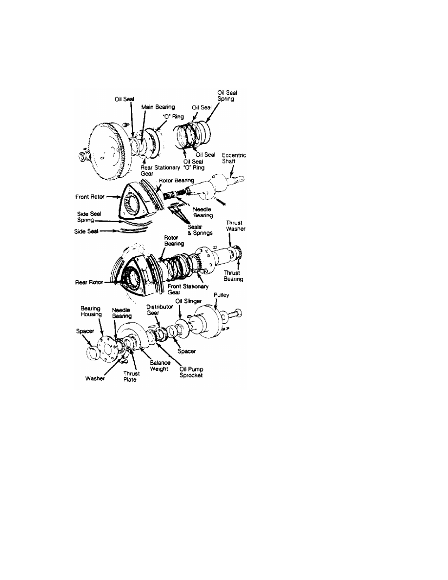
Fig. 1:  Exploded View of Rotors & Eccentric Shaft Assembly

         3) Remove air cleaner assembly. Disconnect the following
tubes and hoses: Oil hoses at cooler, radiator hoses, automatic
transmission cooler lines (if equipped), heater hoses, fuel supply and
return lines, vacuum and evaporative hoses, and air pipe at rear
of intake manifold.
         4) Remove cooling fan and drive assembly, radiator, and
radiator shroud assembly. Disconnect connector and "B" terminal wire
from alternator. Disconnect connector from throttle sensor.
         5) Without disconnecting refrigerant lines, remove compressor
and air conditioning condenser (if equipped) and tie out of the way.
         6) Disconnect choke heater connector. Disconnect accelerator,
choke and hot start assist cables. Disconnect any remaining wires,
tubes or linkages between engine and chassis at top of engine. Remove
upper engine-to-transmission bolts.
         7) Raise and support vehicle. Remove starter. Remove lower
engine-to-transmission bolts. Remove exhaust pipe front cover. Remove

1.1L ROTARY

Article Text (p. 3)

1983 Mazda RX7

For www.iluvmyrx7.com    

Copyright © 1998 Mitchell Repair Information Company, LLC

Sunday, August 26, 2001  04:57PM

nuts and bolts, and disconnect exhaust pipe from exhaust manifold.
Support front catalytic converter.
         8) Support front of transmission with jack and remove left
and right engine mount nuts. Attach sling to engine and take up slack.
Pull engine forward to clear clutch shaft, then lift engine from
vehicle.

         Installation
         To install engine, reverse removal procedure ensuring that
linkages, tubes and     electrical connections are restored in
original position. Refill all fluids to specified levels, warm up
engine and check for leaks.

         DISASSEMBLY

NOTE:    To ease engine disassembly, manufacturer recommends use of
         special engine stand (49 0107 680A) and hanger (49 1114 005).

         1) Loosen drive belts and hoses, and remove air pump and
alternator. Disconnect metering oil pump connecting rod and hoses at
metering oil pump outlets. Remove exhaust manifold cover. Remove
intake manifold and carburetor. Remove gasket and "O" ring.
         2) Remove exhaust manifold, engine mount and distributor .
Remove, oil filter and cover from front housing. Remove water pump and
drive pulley for air conditioning compressor (if equipped).
         3) Turn engine over, and remove oil pan and strainer. Install
flywheel brake (49 1881 060) on manual transmission models or stopper
(49 1881 055) on automatic transmission models.
         4) Remove eccentric shaft pulley. Take off front cover with
gasket, and slide distributor gear off shaft. Remove "O" ring from oil
passage. Remove oil pump sprocket nut. See Fig. 2. Slide oil pump
sprocket, eccentric shaft sprocket and drive chain off together.
Remove oil pump.

Fig. 2:  Oil Pump Drive and Sprocket Removal
Pump drive and sprocket must be removed together.

         5) Remove balance weight and following parts in order: Thrust

1.1L ROTARY

Article Text (p. 4)

1983 Mazda RX7

For www.iluvmyrx7.com    

Copyright © 1998 Mitchell Repair Information Company, LLC

Sunday, August 26, 2001  04:57PM

washer, needle bearing, bearing housing, needle bearing, spacer and
thrust plate.
         6) On manual transmission models, remove clutch assembly. Use
puller to remove flywheel. On automatic transmission models, remove
drive plate. Use puller to remove counterweight.
         7) Remove tension bolts on rear housing in sequence. See
Fig. 3. Loosen in 2 or 3 steps. Lift rear housing off shaft. Remove
any seals stuck to rotor sliding surface, and place them back in
original positions. Remove seals and "O" rings from face of rear rotor
housing.

Fig. 3:  Loosening Sequence of Tension Bolts
Loosen in 2 or 3 steps.

         8) Attach dowel puller (49 0813 215A), and pull tubular
dowels off rear rotor housing. See Fig. 4. Hold rotor housing by hand
to keep it from moving up, and remove rear rotor housing. Use caution
to avoid dropping apex seals and side pieces of rear rotor. Remove
seals and "O" ring from front side of rear rotor housing.
         9) Remove side pieces, apex seals and springs from rear rotor
and store in order for reassembly. Remove all corner seals, corner
seal springs, side seals and side seal springs and store in order for
reassembly. Remove rear rotor, and place on clean pad with internal
gear side down.
         10) Remove seals and springs on remaining side of rotor, and
store in order for reassembly. Place protector on seal inner lip, and
remove outer seal with remover (49 0813 225). Remove inner seal.
Remove seals and springs and store in order for reassembly. Mark rear
rotor for assembly identification.
         11) Attach puller, and while holding housing down, pull
tubular dowels off intermediate housing. Remove intermediate housing

1.1L ROTARY

Article Text (p. 5)

1983 Mazda RX7

For www.iluvmyrx7.com    

Copyright © 1998 Mitchell Repair Information Company, LLC

Sunday, August 26, 2001  04:57PM

by sliding beyond rear rotor journal on eccentric shaft. Carefully
lift out eccentric shaft to avoid damage to rotor bearing and main
bearing. Repeat steps 6) through 8) to remove front rotor housing and
rotor assembly.

Fig. 4:  Extracting Tubular Dowels from Engine
Hold housing down with hand.

         INSPECTION & OVERHAUL

         Front, Intermediate & Rear Housings
         1) Clean housings, using extra fine emery paper to remove
carbon deposits from rotor running surface. Use ketone or thinner to
remove sealing agent.
         2) Place a straightedge across housing surface in positions
shown in Fig. 5. Using a feeler gauge, measure distortion of front
housing. Replace housing if distortion limit of .0016" (.04 mm) is
exceeded.

Fig. 5:  Straightedge Positions for Checking Housing Distortions
Replace if warpage exceeds limit.

         3) Remove oil pressure control valve and spring from front
cover. Check for damage or corrosion. Replace if defective. Measure


Content   ..  20  21  22  23   ..