Mazda CX 7. Manual - part 435


  Index      Mazda     Mazda CX 7 - service repair manual 2007 year


Search            


Content   ..  433  434  435  436   ..


Mazda CX 7. Manual - part 435


INSTRUMENTATION/DRIVER INFO. 

09-22–9

09-22

Check code 23

Check code 25

6

Inspect the wiring harness and connector between instrument cluster and fuel gauge sender unit.

• If there is any malfunction, repair or replace the wiring harness or connector.

• If there is no malfunction, replace the instrument cluster.
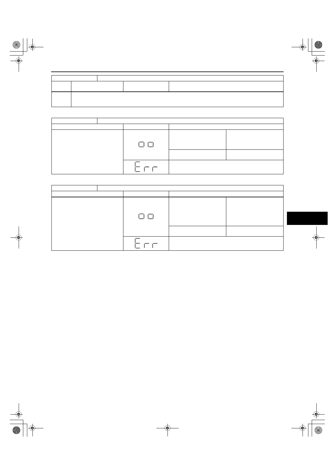
Check code 23

Fuel gauge operation signal

INSPECTION CONDITION

DISPLAY

ACTION

After selecting check code 23, wait 
approx. 2 s.

The fuel gauge indicates 
status in the following order 
approx. every 2 s.

• F → 1/2 → E → F (fixed)

The fuel gauge is normal.

Except above

Replace the instrument 
cluster.

Replace the instrument cluster.

Check code 25

Water temperature gauge operation signal

INSPECTION CONDITION

DISPLAY

ACTION

After selecting check code 25, wait 
approx. 2 s.

The water temperature gauge 
indicates status in the 
following order approx. every 
2 s
.

• H → Center → C → H 

(fixed)

The water temperature gauge 
is normal.

Except above

Replace the instrument 
cluster.

Replace the instrument cluster.

Check code 22

Fuel level signal

STEP

INSPECTION 

CONDITION

DISPLAY

ACTION

1871-1U-06B(09-22).fm  9 ページ  2006年3月15日 水曜日 午後12時56分

INSTRUMENTATION/DRIVER INFO. 

09-22–10

Check code 26

Check code 55

Check code 26

Odometer/tripmeter display signal

INSPECTION CONDITION

DISPLAY

ACTION

Select check code 26.

• Display is normal.

• Warning and indicator 

light illuminated.
— Generator warning light

— DSC/TCS indicator 

light

— ABS warning light

— Brake system warning 

light

— Cruise set indicator 

light

— Cruise main indicator 

light

— TCS OFF light

— Selector indicator light

— Door ajar warning light

— Seat belt warning light

— Air bag system warning 

light

— Turn indicator light

— Oil pressure warning 

light

— MIL

— Keyless indicator light

— Keyless warning light

— Security light

— AT warning light

• The odometer/tripmeter is 

normal.

• Warning and indicator is 

normal.

Except above

Replace the instrument 
cluster.

Check code 55

Dimmer switch ON/OFF signal

STEP

INSPECTION 

CONDITION

DISPLAY

ACTION

1

After selecting the check 
code 55, press and hold 
the dimmer switch. 
(Dimmer switch ON)

Go to the next step.

Replace the instrument cluster.

2

Release the dimmer 
switch. (Dimmer switch 
OFF)

Replace the instrument cluster.

Input signal to the instrument cluster is normal.

1871-1U-06B(09-22).fm  10 ページ  2006年3月15日 水曜日 午後12時56分

INSTRUMENTATION/DRIVER INFO. 

09-22–11

09-22

Check code 57

Check code 59
Diagnostic procedure

End Of Sie

Check code 57

Panel light control signal

INSPECTION CONDITION

DISPLAY

ACTION

Turn the headlight switch to the TNS 
position.
After selecting check code 57, wait 
approx. 2 s.

Illumination light (hazard 
warning switch, center panel 
unit, etc.) flashes three 
times
.

The panel light control signal 
is normal.

Except above

Verify that the voltage of 
instrument cluster terminal 1F 
is B+.

• If the voltage is as 

specified, replace the 
instrument cluster.

• If the voltage is not as 

specified, inspect the 
following parts: 
— Illumination light 

(hazard warning 
switch, center panel 
unit, etc.)

— Wiring harness 

(Instrument cluster— 
illumination lights— 
TNS relay)

Check code 59

CAN system/fuel system

STEP

INSPECTION

INDICATION

ACTION

1

The three digits number is 
indicated after selecting 
check code 59. Confirm 
the first digit from the right.

The CAN system is okay.
Go to next step.

The DTC of CAN system is detected.
Perform the DTC inspection. (See 09-02D-7 DTC 
TABLE[MULTIPLEX COMMUNICATION SYSTEM])

• If the CAN system is okay, replace the instrument cluster.

Go to next step.

2

Confirm the second digit 
from the right.

The wiring harnesses between the fuel gauge sender unit 
and instrument cluster are okay.
Go to next step.

Inspect following parts.

• Fuel gauge sender unit

• Wiring harness (Fuel gauge sender unit— instrument 

cluster)
— If fuel gauge sender unit and wiring harness are okay, 

replace the instrument cluster.

Go to next step.

3

Confirm the third digit from 
the right.

The fuel pulse signal from the PCM is okay.

Inspect the PCM.
(See01-02-7 ON-BOARD DIAGNOSTIC TEST[L3 WITH TC], 
01-40-6 PCM INSPECTION[L3 WITH TC])

• If the PCM is okay, replace the instrument cluster.

(FLASHING)

First digit from 
the right

First digit from 
the right

Second digit 
from the right

Second digit 
from the right

Third digit 
from the right

Third digit 
from the right

1871-1U-06B(09-22).fm  11 ページ  2006年3月15日 水曜日 午後12時56分

INSTRUMENTATION/DRIVER INFO. 

09-22–12

DATA MONITORING AND RECORDING PROCEDURE

id092200801500

1. Connect the M-MDS or equivalent to the DLC-2 

(16-pin).

2. After the vehicle is identified, select the following 

items from the initialization screen of the M-MDS.
When using the IDS (notebook PC)

• Select the “Toolbox” tab.

• Select “DataLogger”.

• Select “Module”.

• Select “HEC”.

When using the PDS (pocket PC)

• Select “Module Tests”.

• Select “HEC”.

• Select “DataLogger”.

3. Verify the data monitor items.

Indication Item Table

End Of Sie

WM: FUEL GAUGE SENDER UNIT

FUEL GAUGE SENDER UNIT REMOVAL/INSTALLATION[AWD]

id0922008019b4

Fuel Gauge Sender Unit

1. Remove the fuel gauge sender unit. (See 01-14-11 FUEL PUMP UNIT REMOVAL/INSTALLATION[L3 WITH 

TC])

2. Install in the reverse order of removal.

Fuel Gauge Sender Sub-Unit

Warning

• Fuel line spills and leakage are dangerous. Fuel can ignite and cause serious injuries or death and 

damage. Fuel can also irritate skin and eyes. To prevent this, always complete the “Fuel Line 
Safety Procedure”.

• Fuel line spills and leakage are dangerous. Fuel can ignite and cause serious injuries or death and 

damage. Fuel can also irritate skin and eyes. To prevent this, before performing the fuel pump unit 
removal/installation, always complete the “Fuel Leak Inspection After Fuel Pump Unit 
Installation”.

• A person charged with static electricity could cause a fire or explosion, resulting in death or 

serious injury. Before draining fuel, make sure to discharge static electricity by touching the 
vehicle body.

Caution

• Because the fuel tank is constructed such that the fuel level is higher than the installation surface 

of the fuel pump, fuel leakage could occur. If the fuel gauge indicates a fuel level of half or more, 
perform the following Steps 1-6 to drain approx. 10 L {11 US gal, 8.8 lmp gal} of fuel.

• Disconnecting/connecting the quick release connector without cleaning it may possibly cause 

damage to the fuel pipe and quick release connector. Always clean the quick release connector 
joint area before disconnecting/connecting using a cloth or soft brush, and make sure that it is 
free of foreign material.

• To prevent the SST from coming off the fuel pump cap while performing the work, always perform 

the removal/installation procedure with 2 people. One person presses the SST against cap from 
directly above, while the other person rotates the SST.

DLC-2

acxuuw00001755

Monitor item

Input-output signal/part 

name

Unit/State

Terminal

IC_DTC_CNT

Number of continuous DTCs

— 

— 

IC_ECT

Water temperature gauge

°C

2R,  2T

IC_NUMKEYS

Number of key ID numbers 
registered with the vehicle

— — 

IC_ODO_CNT

Odometer

m

2R, 2T

IC_SPDMTR

Speedometer

KPH

IC_TACHO

Tachometer

RPM

1871-1U-06B(09-22).fm  12 ページ  2006年3月15日 水曜日 午後12時56分


Content   ..  433  434  435  436   ..