Mazda CX 7. Manual - part 403


  Index      Mazda     Mazda CX 7 - service repair manual 2007 year


Search            


Content   ..  401  402  403  404   ..


Mazda CX 7. Manual - part 403


SUNROOF 

09-15–7

09-15

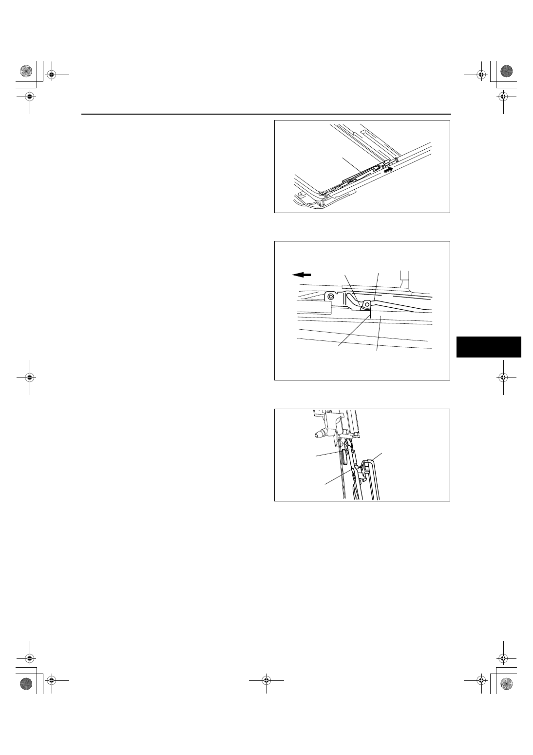
2. Slide the guide to the rear of the sunroof frame, 

and remove the guide and decoration link as a 
single unit.

Guide Assembly Note

1. Move the pin to the position shown in the figure.

Decoration Link Assembly Note

1. Set the guide pin to the decoration link.

End Of Sie

WM: SUNROOF MOTOR

GUIDE

acxuuw00001198

FRONT

PIN

GUIDE

MARK

FRAME

acxuuw00001199

DECORATION LINK

PIN

GUIDE

acxuuw00001200

SUNROOF 

09-15–8

SUNROOF MOTOR REMOVAL/INSTALLATION

id091500805000

1. Disconnect the negative battery cable.
2. Remove the following parts:

(1) A-pillar lower trim (See 09-17-16 A-PILLAR LOWER TRIM REMOVAL/INSTALLATION.)
(2) A-pillar trim (See 09-17-15 A-PILLAR TRIM REMOVAL/INSTALLATION.)
(3) Front scuff plate inner (See 09-17-19 FRONT SCUFF PLATE REMOVAL/INSTALLATION.)
(4) Rear scuff plate inner (See 09-17-19 REAR SCUFF PLATE REMOVAL/INSTALLATION.)
(5) B-pillar lower trim (See 09-17-16 B-PILLAR LOWER TRIM REMOVAL/INSTALLATION.)
(6) Front seat belt upper anchor installation bolt (See 08-11-2 FRONT SEAT BELT REMOVAL/

INSTALLATION.)

(7) B-pillar upper trim (See 09-17-16 B-PILLAR UPPER TRIM REMOVAL/INSTALLATION.)
(8) Rear seat (See 09-13-7 REAR SEAT REMOVAL/INSTALLATION.)
(9) Sub trunk box (See 09-17-25 SUB TRUNK BOX REMOVAL/INSTALLATION.)
(10)Trunk end trim (See 09-17-24 TRUNK END TRIM REMOVAL/INSTALLATION.)
(11)Trunk side trim (See 09-17-24 TRUNK SIDE TRIM REMOVAL/INSTALLATION.)
(12)C-pillar trim (See 09-17-17 C-PILLAR TRIM REMOVAL/INSTALLATION.)
(13)D-pillar trim (See 09-17-18 D-PILLAR TRIM REMOVAL/INSTALLATION.)
(14)Map light (See 09-18-22 MAP LIGHT REMOVAL/INSTALLATION.)
(15)Sunvisor (See 09-17-26 SUNVISOR REMOVAL/INSTALLATION.)
(16)Assist handle (See 09-17-27 ASSIST HANDLE REMOVAL/INSTALLATION.)
(17)Headliner (See 09-17-27 HEADLINER REMOVAL/INSTALLATION.)

3. Disconnect the sunroof motor connector.
4. Remove the screws, and then remove the sunroof 

motor.

5. Install in the reverse order of removal.

Note

• If the glass panel or the sunroof motor is 

moved with the sunroof motor removed, 
initial position setting of the sunroof motor 
will be required. Perform initial position 
setting referring to the Sunr of Motor 
Assembly Note. (See 09-15-5 SUNROOF 
UNIT DISASSEMBLY/ASSEMBLY.)

End Of Sie

SUNROOF MOTOR INSPECTION

id091500801100

1. Measure the voltage at each terminal (other than terminal G).

• If not as specified, inspect the parts listed under “Inspection item” and the related wiring harnesses.

2. Disconnect the negative battery cable.
3. Verify that continuity at terminal G is as indicated in the Terminal Voltage Table (Reference).
4. If the parts and wiring harnesses are normal but the system still does not work properly, replace the sunroof 

relay.

Terminal voltage table (Reference)

SUNROOF 
MOTOR

SCREW

SUNROOF MOTOR 
CONNECTOR

acxuuw00001228

*

A

J

*

B

C

E

G

SUNROOF MOTOR WIRING 
HARNESS-SIDE CONNECTOR

H

I

acxuuw00001262

Termi

nal

Signal

Connected to

Test condition

Voltage (V)/

Continuity

Inspection item

A

Slide open

Sunroof switch

Sunroof is fully opening.

B+

Sunroof switch

Other

1.0 or less

SUNROOF 

09-15–9

09-15

End Of Sie

WM: DRAIN HOSE

FRONT DRAIN HOSE REMOVAL

id091500801300

1. Disconnect the negative battery cable.
2. Partially peel back the seaming welt.
3. Remove the following parts:

(1) A-pillar lower trim (See 09-17-16 A-PILLAR LOWER TRIM REMOVAL/INSTALLATION.)
(2) A-pillar trim (See 09-17-15 A-PILLAR TRIM REMOVAL/INSTALLATION.)
(3) Front scuff plate inner (See 09-17-19 FRONT SCUFF PLATE REMOVAL/INSTALLATION.)
(4) Rear scuff plate inner (See 09-17-19 REAR SCUFF PLATE REMOVAL/INSTALLATION.)
(5) B-pillar lower trim (See 09-17-16 B-PILLAR LOWER TRIM REMOVAL/INSTALLATION.)
(6) Front seat belt upper anchor installation bolt (See 08-11-2 FRONT SEAT BELT REMOVAL/

INSTALLATION.)

(7) B-pillar upper trim (See 09-17-16 B-PILLAR UPPER TRIM REMOVAL/INSTALLATION.)
(8) Rear seat (See 09-13-7 REAR SEAT REMOVAL/INSTALLATION.)
(9) Sub trunk box (See 09-17-25 SUB TRUNK BOX REMOVAL/INSTALLATION.)
(10)Trunk end trim (See 09-17-24 TRUNK END TRIM REMOVAL/INSTALLATION.)
(11)Trunk side trim (See 09-17-24 TRUNK SIDE TRIM REMOVAL/INSTALLATION.)
(12)C-pillar trim (See 09-17-17 C-PILLAR TRIM REMOVAL/INSTALLATION.)
(13)D-pillar trim (See 09-17-18 D-PILLAR TRIM REMOVAL/INSTALLATION.)
(14)Map light (See 09-18-22 MAP LIGHT REMOVAL/INSTALLATION.)
(15)Sunvisor (See 09-17-26 SUNVISOR REMOVAL/INSTALLATION.)
(16)Assist handle (See 09-17-27 ASSIST HANDLE REMOVAL/INSTALLATION.)
(17)Headliner (See 09-17-27 HEADLINER REMOVAL/INSTALLATION.)
(18)Console panel (See 09-17-15 CONSOLE PANEL REMOVAL/INSTALLATION.)
(19)Console (See 09-17-13 CONSOLE REMOVAL/INSTALLATION.)
(20)Front side trim (See 09-17-18 FRONT SIDE TRIM REMOVAL/INSTALLATION.)
(21)Dashboard under cover
(22)Glove compartment (See 09-17-8 GLOVE COMPARTMENT REMOVAL/INSTALLATION.)
(23)Hood release lever (See 09-14-25 HOOD LATCH AND RELEASE LEVER REMOVAL/INSTALLATION.)
(24)Lower panel (See 09-17-9 LOWER PANEL REMOVAL/INSTALLATION.)
(25)Center panel (See 09-17-8 CENTER PANEL REMOVAL/INSTALLATION.)
(26)Audio unit (See 09-20-4 AUDIO UNIT REMOVAL/INSTALLATION.)
(27)Climate control unit (See 07-40-25 CLIMATE CONTROL UNIT REMOVAL/INSTALLATION [FULL-AUTO 

AIR CONDITIONER].) (See 07-40-25 CLIMATE CONTROL UNIT REMOVAL [MANUAL AIR 
CONDITIONER].) (See 07-40-26 CLIMATE CONTROL UNIT INSTALLATION [MANUAL AIR 
CONDITIONER].)

(28)Knee bolster (See 09-17-12 KNEE BOLSTER REMOVAL/INSTALLATION.)
(29)Meter hood (See 09-17-10 METER HOOD REMOVAL/INSTALLATION.)
(30)Column cover (See 09-17-8 COLUMN COVER REMOVAL/INSTALLATION.)
(31)Instrument cluster (See 09-22-2 INSTRUMENT CLUSTER REMOVAL/INSTALLATION.)
(32)Driver-side air bag module (See 08-10-6 DRIVER-SIDE AIR BAG MODULE REMOVAL/INSTALLATION.)
(33)Steering wheel (See 06-14-6 STEERING WHEEL AND COLUMN REMOVAL/INSTALLATION.)
(34)Combination switch (See 09-18-13 COMBINATION SWITCH REMOVAL/INSTALLATION.)
(35)Steering shaft (See 06-14-6 STEERING WHEEL AND COLUMN REMOVAL/INSTALLATION.)
(36)Dashboard (See 09-17-4 DASHBOARD REMOVAL/INSTALLATION.)

B

Slide close/tilt 
down

Sunroof switch

Sunroof is closing/tilting down.

B+

Sunroof switch

Other

1.0 or less

C

Tilt up

Sunroof switch

Sunroof is tilting up.

B+

Sunroof switch

Other

1.0 or less

E

IG2

A/C fuse

Turn the ignition switch to the 
ON position.

B+

A/C fuse

Other

1.0 or less

G

GND

GND

Under any condition: Check for 
continuity to ground.

Continuity

GND

H

Communication BCM

Because this terminal is for 
communication, good/no good 
judgment by terminal voltage is 
not possible.

— BCM

I

Vehicle speed

Instrument cluster

pulse signal

— 

Instrument cluster

J

Power supply

A/C PWR fuse

Under any condition

B+

A/C PWR fuse

Termi

nal

Signal

Connected to

Test condition

Voltage (V)/

Continuity

Inspection item

SUNROOF 

09-15–10

4. Disconnect the front drain hose from the sunroof frame.
5. Remove the front drain hose from the clips.
6. Pull the front drain hose into the room side.
7. Remove the front drain hose.

End Of Sie

FRONT DRAIN HOSE INSTALLATION

id091500801400

Caution

• If the front drain hose is pinched or bent anywhere, the water in the hose may not discharge and 

enter the inside of the vehicle. During and after installation of the trims and the headliner, always 
make sure there is no interference with the front drain hose. Fix any problem if found.

1. Apply soapy water to the front drain hose inserting area.
2. Insert one end (the wider end) of the front drain hose into the sunroof frame.
3. Install the front drain hose to the clips, parallel to the pillar and free of slack.
4. Insert the front drain hose joint into the hinge pillar inner hole.
5. Install the following parts:

(1) Dashboard (See 09-17-4 DASHBOARD REMOVAL/INSTALLATION.)
(2) Steering shaft (See 06-14-6 STEERING WHEEL AND COLUMN REMOVAL/INSTALLATION.)
(3) Combination switch (See 09-18-13 COMBINATION SWITCH REMOVAL/INSTALLATION.)
(4) Steering wheel (See 06-14-6 STEERING WHEEL AND COLUMN REMOVAL/INSTALLATION.)
(5) Driver-side air bag module (See 08-10-6 DRIVER-SIDE AIR BAG MODULE REMOVAL/INSTALLATION.)
(6) Instrument cluster (See 09-22-2 INSTRUMENT CLUSTER REMOVAL/INSTALLATION.)
(7) Column cover (See 09-17-8 COLUMN COVER REMOVAL/INSTALLATION.)
(8) Meter hood (See 09-17-10 METER HOOD REMOVAL/INSTALLATION.)
(9) Knee bolster (See 09-17-12 KNEE BOLSTER REMOVAL/INSTALLATION.)
(10)Climate control unit (See 07-40-25 CLIMATE CONTROL UNIT REMOVAL/INSTALLATION [FULL-AUTO 

AIR CONDITIONER].) (See 07-40-25 CLIMATE CONTROL UNIT REMOVAL [MANUAL AIR 
CONDITIONER].) (See 07-40-26 CLIMATE CONTROL UNIT INSTALLATION [MANUAL AIR 
CONDITIONER].)

(11)Audio unit (See 09-20-4 AUDIO UNIT REMOVAL/INSTALLATION.)
(12)Center panel (See 09-17-8 CENTER PANEL REMOVAL/INSTALLATION.)
(13)Lower panel (See 09-17-9 LOWER PANEL REMOVAL/INSTALLATION.)
(14)Hood release lever (See 09-14-25 HOOD LATCH AND RELEASE LEVER REMOVAL/INSTALLATION.)
(15)Glove compartment (See 09-17-8 GLOVE COMPARTMENT REMOVAL/INSTALLATION.)
(16)Dashboard under cover
(17)Front side trim (See 09-17-18 FRONT SIDE TRIM REMOVAL/INSTALLATION.)
(18)Console (See 09-17-13 CONSOLE REMOVAL/INSTALLATION.)
(19)Console panel (See 09-17-15 CONSOLE PANEL REMOVAL/INSTALLATION.)
(20)Headliner (See 09-17-27 HEADLINER REMOVAL/INSTALLATION.)
(21)Assist handle (See 09-17-27 ASSIST HANDLE REMOVAL/INSTALLATION.)
(22)Sunvisor (See 09-17-26 SUNVISOR REMOVAL/INSTALLATION.)
(23)Map light (See 09-18-22 MAP LIGHT REMOVAL/INSTALLATION.)
(24)D-pillar trim (See 09-17-18 D-PILLAR TRIM REMOVAL/INSTALLATION.)
(25)C-pillar trim (See 09-17-17 C-PILLAR TRIM REMOVAL/INSTALLATION.)
(26)Trunk side trim (See 09-17-24 TRUNK SIDE TRIM REMOVAL/INSTALLATION.)
(27)Trunk end trim (See 09-17-24 TRUNK END TRIM REMOVAL/INSTALLATION.)
(28)Sub trunk box (See 09-17-25 SUB TRUNK BOX REMOVAL/INSTALLATION.)
(29)Rear seat (See 09-13-7 REAR SEAT REMOVAL/INSTALLATION.)
(30)B-pillar upper trim (See 09-17-16 B-PILLAR UPPER TRIM REMOVAL/INSTALLATION.)
(31)Front seat belt upper anchor installation bolt (See 08-11-2 FRONT SEAT BELT REMOVAL/

INSTALLATION.)

(32)B-pillar lower trim (See 09-17-16 B-PILLAR LOWER TRIM REMOVAL/INSTALLATION.)
(33)Rear scuff plate inner (See 09-17-19 REAR SCUFF PLATE REMOVAL/INSTALLATION.)
(34)Front scuff plate inner (See 09-17-19 FRONT SCUFF PLATE REMOVAL/INSTALLATION.)
(35)A-pillar trim (See 09-17-15 A-PILLAR TRIM REMOVAL/INSTALLATION.)
(36)A-pillar lower trim (See 09-17-16 A-PILLAR LOWER TRIM REMOVAL/INSTALLATION.)

6. Install the seaming welt.

End Of Sie

BODY

GROMMET

B

B

B

C

C

D

C

C

B

A

A

D

Sec. A

A

Sec. B

B

Sec. C

C

Sec. D

D

acxuuw00001237


Content   ..  401  402  403  404   ..