Mazda CX 7. Manual - part 344
ON-BOARD DIAGNOSTIC [BCM]
09-02F–11
09-02F
DTC B1614[BCM]
id0902f5831900
Diagnostic procedure
DTC B1614
Rear wiper interval switch input circuit short to ground
DETECTION
CONDITION
Short to GND in wiring harness between BCM and rear wiper and washer switch (INT)
POSSIBLE
CAUSE
• Short to GND in wiring harness between BCM terminal 3R and windshield wiper and washer switch
terminal L
• Windshield wiper and washer switch malfunction
• BCM malfunction
STEP
INSPECTION
ACTION
1
INSPECT WINDSHIELD WIPER AND
WASHER SWITCH CONNECTOR
• Disconnect the windshield wiper and washer
switch connector.
• Inspect the windshield wiper and washer
switch connector terminals for poor
connection (such as damaged/pulled-out
pins, and corrosion).
• Is there any malfunction?
Yes
Repair or replace the terminal, then go to Step 5.
No
Go to the next step.
2
INSPECT BCM CONNECTOR
• Disconnect the BCM connector.
• Inspect the BCM connector terminals for
poor connection (such as damaged/pulled-
out pins, and corrosion).
• Is there any malfunction?
Yes
Repair or replace the terminal, then go to Step 5.
No
Go to the next step.
3
INSPECT WINDSHIELD WIPER AND
WASHER SWITCH SIGNAL CIRCUIT FOR
SHORT TO GND
• Inspect for continuity between BCM terminal
3R (wiring harness-side) and body GND.
• Is there continuity?
Yes
Repair or replace the wiring harness for a possible short to
GND, then go to Step 5.
No
Go to the next step.
4
INSPECT WINDSHIELD WIPER AND
WASHER SWITCH
• Inspect the windshield wiper and washer
switch.
(See 09-19-8 WINDSHIELD WIPER AND
WASHER SWITCH INSPECTION.)
• Is there any malfunction?
Yes
Replace the windshield wiper and washer switch, then go to
the next step.
(See 09-19-8 WIPER AND WASHER SWITCH REMOVAL/
INSTALLATION.)
No
Go to the next step.
5
VERIFY TROUBLESHOOTING COMPLETED
• Make sure to reconnect all disconnected
connectors.
• Clear the DTC from the BCM memory using
the M-MDS.
• Perform the self-test.
(See 09-02F-26 BCM SELF-TEST[BCM].)
• Is the same DTC present?
Yes
Replace the BCM.
(See 09-40-1 BODY CONTROL MODULE (BCM)
REMOVAL/INSTALLATION.)
No
DTC troubleshooting completed.
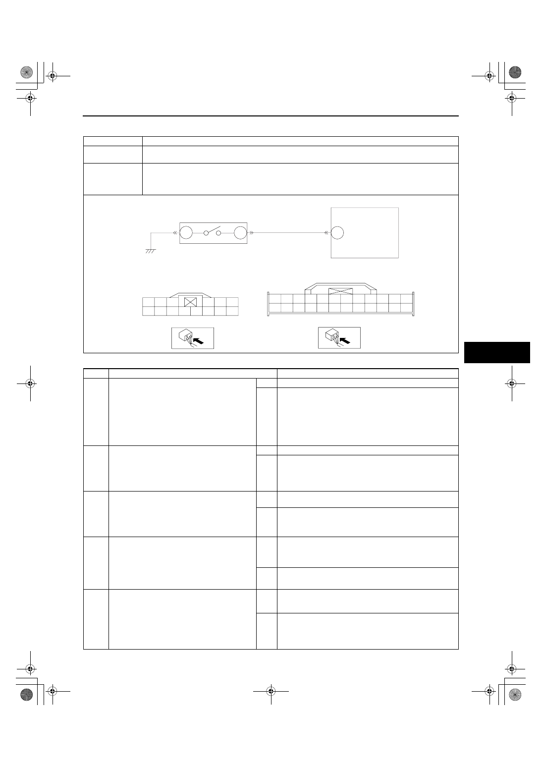
3R
L
WINDSHIELD WIPER AND
WASHER SWITCH
BCM
F
WINDSHIELD WIPER AND WASHER
SWITCH WIRING HARNESS-SIDE
CONNECTOR
BCM WIRING HARNESS-SIDE
CONNECTOR
3E
3G
3I
3K
3M
3O
3A
3C
3N
3L
3P
3H
3D
3B
3F
3J
3Q
3R
3S
3T
3U
3V
3W
3X
F
M
N
O
P
A
B
C
D
E
H
K
J
L
1871-1U-06B(09-02F).fm 11 ページ 2006年3月15日 水曜日 午前11時41分