Mazda CX 7. Manual - part 333


  Index      Mazda     Mazda CX 7 - service repair manual 2007 year


Search            


Content   ..  331  332  333  334   ..


Mazda CX 7. Manual - part 333


ON-BOARD DIAGNOSTIC [IMMOBILIZER SYSTEM (KEYLESS ENTRY SYSTEM)]

09-02C–3

09-02C

M-MDS

1. Connect the M-MDS to the DLC-2.
2. Verify if any DTCs are displayed.

• If any DTCs are displayed, carry out 

troubleshooting according to the 
corresponding DTC inspection.

3. Disconnect the M-MDS.

End Of Sie

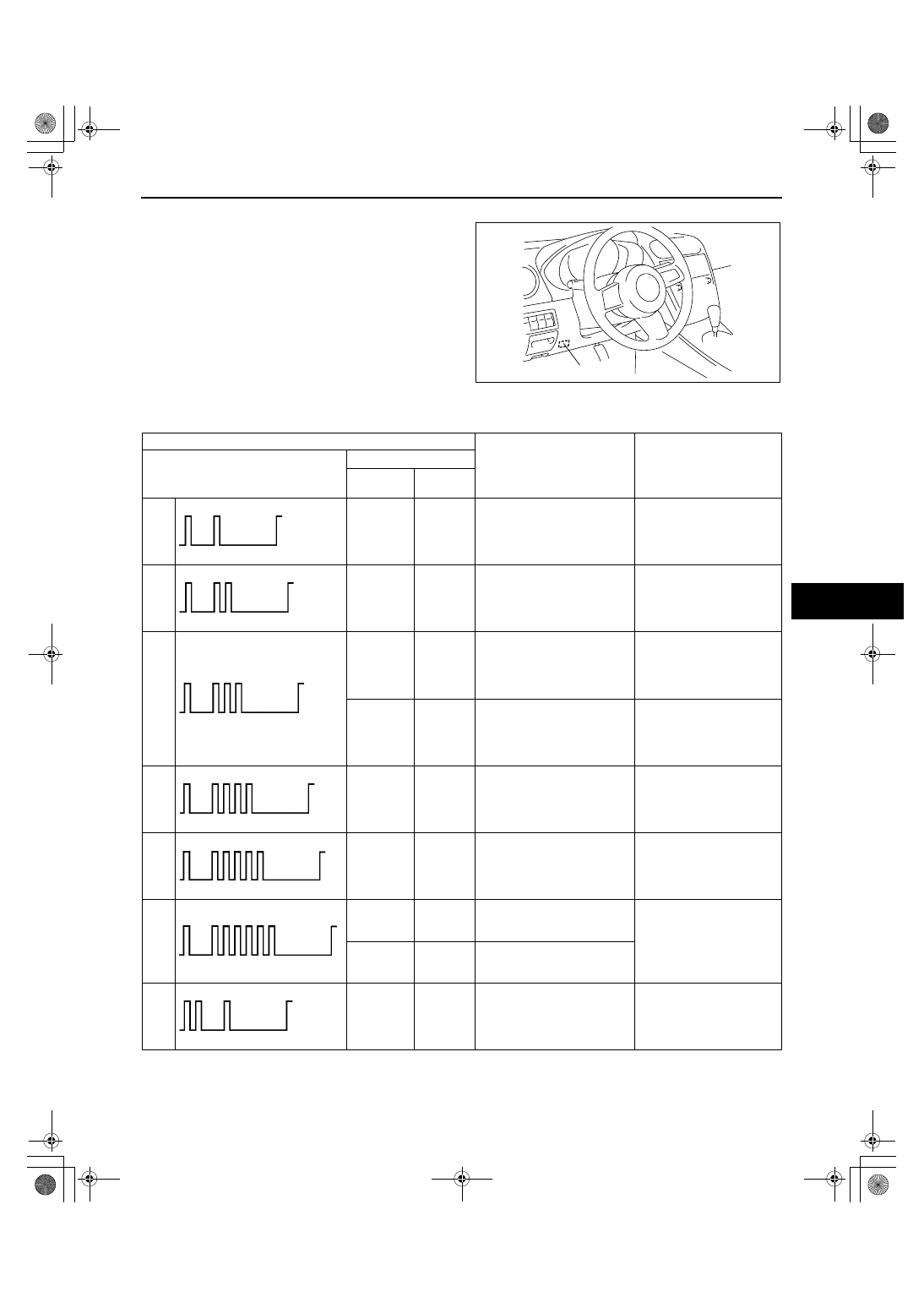
DTC TABLE[IMMOBILIZER SYSTEM (KEYLESS ENTRY SYSTEM)]

id0902e5800300

DLC-2

acxuuw00002447

DTC 

Detection condition

Page

Security light flashing pattern

M-MDS display

*

Instrument 

cluster

PCM

11

B1681

P1260

No detected communication 
with the coil

09-02C-5 SECURITY 
LIGHT 11, DTC B1681/
P1260[IMMOBILIZER 
SYSTEM (KEYLESS 
ENTRY SYSTEM)]

12

B2103

P1260

• Coil antenna malfunction

• The PCM determined a 

malfunction in the coil 
antenna even though it is 
normal.

09-02C-7 SECURITY 
LIGHT 12, DTC B2103/
P1260[IMMOBILIZER 
SYSTEM (KEYLESS 
ENTRY SYSTEM)]

13

B1600

P1260

The key ID number data 
cannot be read.

09-02C-7 SECURITY 
LIGHT 13, DTC B1600/
P1260[IMMOBILIZER 
SYSTEM (KEYLESS 
ENTRY SYSTEM)]

B2431

P1260

Key ID number registration 
error

09-02C-9 SECURITY 
LIGHT 13, DTC B2431/
P1260[IMMOBILIZER 
SYSTEM (KEYLESS 
ENTRY SYSTEM)]

14

B1602

P1260

The instrument cluster cannot 
read key ID number data 
normally.

09-02C-10 SECURITY 
LIGHT 14, DTC B1602/
P1260[IMMOBILIZER 
SYSTEM (KEYLESS 
ENTRY SYSTEM)]

15

B1601

P1260

The instrument cluster has 
detected unregistered key ID 
number.

09-02C-11 SECURITY 
LIGHT 15, DTC B1601/
P1260[IMMOBILIZER 
SYSTEM (KEYLESS 
ENTRY SYSTEM)]

16

U2510

P1260

Communication error between 
the instrument cluster and the 
PCM (no response)

09-02C-12 SECURITY 
LIGHT 16, DTC U2510/
P1260, U1147/
P1260[IMMOBILIZER 
SYSTEM (KEYLESS 
ENTRY SYSTEM)]

U1147

P1260

Communication error between 
the instrument cluster and the 
PCM (mismatched conditions)

21

B1213

P1260

Only one key ID number is 
registered.

09-02C-12 SECURITY 
LIGHT 21, DTC B1213/
P1260[IMMOBILIZER 
SYSTEM (KEYLESS 
ENTRY SYSTEM)]

1871-1U-06B(09-02C).fm  3 ページ  2006年3月15日 水曜日 午前11時39分

ON-BOARD DIAGNOSTIC [IMMOBILIZER SYSTEM (KEYLESS ENTRY SYSTEM)]

09-02C–4

*

: The letters at the beginning of each DTC are only displayed when using the M-MDS, and refer to the following: 

B= Body system, P= Powertrain system, U= Network communication system.

End Of Sie

PID/DATA MONITOR INSPECTION[IMMOBILIZER SYSTEM (KEYLESS ENTRY SYSTEM)]

id0902e5800400

1. Connect the M-MDS to the DLC-2.
2. Display the PID/data monitor items.

• Verify a displayed item according to the PID/

data monitor table.

3. Disconnect the M-MDS.

End Of Sie

PID/DATA MONITOR TABLE[IMMOBILIZER SYSTEM (KEYLESS ENTRY SYSTEM)]

id0902e5800500

End Of Sie

22

B2141

P1260

Communication error between 
the instrument cluster and the 
PCM (data transfer error)

09-02C-13 SECURITY 
LIGHT 22, DTC B2141/
P1260[IMMOBILIZER 
SYSTEM (KEYLESS 
ENTRY SYSTEM)]

23

B2139

P1260

ID number data in the PCM 
and the instrument cluster do 
not match.

09-02C-14 SECURITY 
LIGHT 23, DTC B2139/
P1260[IMMOBILIZER 
SYSTEM (KEYLESS 
ENTRY SYSTEM)]

Not illuminated

B1342

-

Instrument cluster malfunction

09-02C-14 DTC 
B1342[IMMOBILIZER 
SYSTEM (KEYLESS 
ENTRY SYSTEM)]

DTC 

Detection condition

Page

Security light flashing pattern

M-MDS display

*

Instrument 

cluster

PCM

DLC-2

acxuuw00002457

PID name (definition)

Detection condition

NUMKEYS
 (Number of key ID numbers registered in the instrument cluster)

Number of key ID numbers registered: 0— 8

1871-1U-06B(09-02C).fm  4 ページ  2006年3月15日 水曜日 午前11時39分

ON-BOARD DIAGNOSTIC [IMMOBILIZER SYSTEM (KEYLESS ENTRY SYSTEM)]

09-02C–5

09-02C

SECURITY LIGHT 11, DTC B1681/P1260[IMMOBILIZER SYSTEM (KEYLESS ENTRY SYSTEM)]

id0902e5800600

Diagnostic Procedure

SECURITY LIGHT: 11

No detected communication with the coil antenna

 DTC: B1681/P1260

DETECTION CONDITION

• No detected communication with the coil antenna

POSSIBLE CAUSE

• Coil antenna malfunction

• Instrument cluster malfunction

• Malfunction in the related wiring harnesses

STEP

INSPECTION

ACTION

1

INSPECT COIL ANTENNA POWER SUPPLY 

SYSTEM

• Disconnect the coil antenna connector.

• Turn the ignition switch to the ON position.

• Measure the voltage at coil antenna terminal D.

— Is the voltage 8 V or more?

Yes

Go to the next step.

No

Repair the wiring harness.

2

INSPECT WIRING HARNESS BETWEEN 

COIL ANTENNA AND GROUND

• Turn the ignition switch to the LOCK position.

• Inspect the wiring harness between coil antenna 

terminal C and ground for the following: 

— Short to power supply

— Open circuit

• Is the wiring harness normal?

Yes

Go to the next step.

No

Repair the wiring harness.

3

INSPECT COIL ANTENNA INPUT SIGNAL 

CIRCUIT

• Connect the coil antenna connector.

• Turn the ignition switch to the ON position.

• Measure the voltage at coil antenna terminal B.

— Is the voltage 8 V or more?

Yes

Go to Step 7.

No

Go to the next step.

IG1

D

A

C

B

D

C

B

A

2Q

2S

1E

INSTRUMENT CLUSTER

COIL ANTENNA

INSTRUMENT CLUSTER

WIRING HARNESS-SIDE CONNECTOR

COIL ANTENNA 

WIRING HARNESS-SIDE CONNECTOR

2Q

2S

1871-1U-06B(09-02C).fm  5 ページ  2006年3月15日 水曜日 午前11時39分

ON-BOARD DIAGNOSTIC [IMMOBILIZER SYSTEM (KEYLESS ENTRY SYSTEM)]

09-02C–6

End Of Sie

4

INSPECT COIL ANTENNA INPUT SIGNAL 

CIRCUIT

• Turn the ignition switch to the LOCK position.

• Disconnect the instrument cluster connector.

• Turn the ignition switch to the ON position.

• Measure the voltage at instrument cluster 

terminal 2S.
— Is the voltage 8 V or more?

Yes

Replace the instrument cluster and perform the 
resetting procedure for the immobilizer system when 
replacing the instrument cluster.
 (See 09-22-2 INSTRUMENT CLUSTER REMOVAL/
INSTALLATION.)
 (See 09-14-20 IMMOBILIZER SYSTEM COMPONENT 
REPLACEMENT/KEY ADDITION AND 
CLEARING[KEYLESS ENTRY SYSTEM].)

No

Go to the next step.

5

INSPECT COMMUNICATION CIRCUIT 

(INPUT) FOR CONTINUITY

• Turn the ignition switch to the LOCK position.

• Is there continuity between coil antenna terminal 

B and instrument cluster terminal 2S?

Yes

Go to the next step.

No

Repair the wiring harness.

6

INSPECT COIL ANTENNA INPUT SIGNAL 

CIRCUIT

• Measure the resistance between coil antenna 

terminal B and ground.
— Is the resistance 10 kilohms or more?

Yes

Replace the coil antenna.
 (See 09-14-11 COIL ANTENNA REMOVAL/
INSTALLATION.)

No

Repair the wiring harness.

7

INSPECT COIL ANTENNA OUTPUT SIGNAL 

CIRCUIT

• Connect the coil antenna connector and the 

instrument cluster connector.

• Turn the ignition switch to the ON position.

• Measure the voltage at coil antenna terminal A.

— Is the voltage 8 V or more?

Yes

Replace the coil antenna.
 (See 09-14-11 COIL ANTENNA REMOVAL/
INSTALLATION.)

No

Go to the next step.

8

INSPECT COIL ANTENNA OUTPUT SIGNAL 

CIRCUIT

• Turn the ignition switch to the LOCK position.

• Disconnect the coil antenna connector.

• Turn the ignition switch to the ON position.

• Measure the voltage at coil antenna terminal A.

— Is the voltage 8 V or more?

Yes

Replace the coil antenna.
 (See 09-14-11 COIL ANTENNA REMOVAL/
INSTALLATION.)

No

Go to the next step.

9

INSPECT COMMUNICATION CIRCUIT 

(OUTPUT) FOR CONTINUITY

• Turn the ignition switch to the LOCK position.

• Disconnect the instrument cluster connector.

• Is there continuity between coil antenna terminal 

A and instrument cluster terminal 2Q?

Yes

Repair the wiring harness.

No

Go to the next step.

10

INSPECT COIL ANTENNA OUTPUT SIGNAL 

CIRCUIT

• Measure the resistance between instrument 

cluster terminal 2Q and ground.

— Is the resistance 10 kilohms or more?

Yes

Replace the instrument cluster and perform the 
resetting procedure for the immobilizer system when 
replacing the instrument cluster.
 (See 09-22-2 INSTRUMENT CLUSTER REMOVAL/
INSTALLATION.)
 (See 09-14-20 IMMOBILIZER SYSTEM COMPONENT 
REPLACEMENT/KEY ADDITION AND 
CLEARING[KEYLESS ENTRY SYSTEM].)

No

Repair the wiring harness.

STEP

INSPECTION

ACTION

1871-1U-06B(09-02C).fm  6 ページ  2006年3月15日 水曜日 午前11時39分


Content   ..  331  332  333  334   ..