Mazda CX 7. Manual - part 317


  Index      Mazda     Mazda CX 7 - service repair manual 2007 year


Search            


Content   ..  315  316  317  318   ..


Mazda CX 7. Manual - part 317


AIR BAG SYSTEM 

08-10–5

08-10

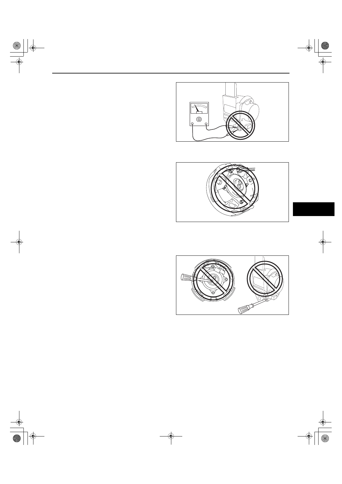
Pre-tensioner Seat Belt Inspection

• Inspecting a pre-tensioner seat belt using a 

tester can operate (deploy) the pre-tensioner 
seat belt, which may cause serious injury. Do 
not use a tester to inspect a pre-tensioner 
seat belt. Always use the on-board diagnostic 
function to diagnose the pre-tensioner seat 
belt for malfunctions.

End Of Sie

AIR BAG SYSTEM SERVICE CAUTIONS

id081000800300

Air Bag System Component Disassembly

• Disassembling the air bag system 

components could cause it to not operate 
(deploy) normally. Never disassemble any air 
bag system components.

Air Bag Module, Pre-tensioner Seat Belt Handling

• Oil, grease, or water on the air bag modules may cause the air bags and pre-tensioner seat belts to fail 

to operate (deploy) in an accident. Never allow oil, grease, or water to get on the air bag modules or 
pre-tensioner seat belts.

• Inserting a screwdriver or similar object into 

the connector of an air bag module or a pre-
tensioner seat belt may damage the connector 
and cause the air bag module or the pre-
tensioner seat belt to operate (deploy) 
improperly, which may cause serious injury. 
Never insert any foreign objects into the air 
bag module or seat belt connectors.

Seat Weight Sensor Handling

• The seat weight sensor has a built-in strain gauge which may operate improperly if the sensor is 

dropped by itself or when installed to the seat. If it is dropped, replace the seat weight sensor with a 
new one.

• Oil, grease, or water on the seat weight sensor may cause the system to operate (deploy) improperly. 

Never allow oil, grease, or water to get on the seat weight sensor.

• Foreign material in the seat weight sensor components may cause the system to operate (deploy) 

improperly. Always make sure that no foreign material can get into the seat weight sensor.

• Disassembling the seat weight sensor, or tightening any of the nuts and bolts installed to the sensor 

body may cause it to operate (deploy) improperly. Never disassemble the seat weight sensor or tighten 
any of the nuts or bolts installed to the body of the sensor.

NO GOOD

acxuuw00001177

NO GOOD

acxuuw00001178

NO GOOD

NO GOOD

acxuuw00001595

1871-1U-06B(08-10).fm  5 ページ  2006年3月15日 水曜日 午前11時36分

AIR BAG SYSTEM 

08-10–6

Air Bag Module, Pre-tensioner Seat Belt Reuse

• Even if an air bag module or a pre-tensioner seat belt does not operate (deploy) in a collision and does 

not have any external signs of damage, it may have been damaged internally, which may cause 
improper operation. Before reusing a live (undeployed) air bag module and the pre-tensioner seat belts, 
always use the on-board diagnostic to diagnose the air bag module and the pre-tensioner seat belts to 
verify that they have no malfunction.

Air Bag Wiring Harness Repair

• Incorrectly repairing an air bag wiring harness 

can accidentally operate (deploy) the air bag 
module and pre-tensioner seat belts. If a 
problem is found in the air bag wiring 
harness, always replace the wiring harness 
with a new one.

End Of Sie

WM: DRIVER-SIDE AIR BAG MODULE

DRIVER-SIDE AIR BAG MODULE REMOVAL/INSTALLATION

id081000801300

Warning

• Handling the air bag module improperly can accidentally deploy the air bag module, which may 

seriously injure you. Read the air bag system service warnings and cautions before handling the 
air bag module. (See 08-10-3 AIR BAG SYSTEM SERVICE WARNINGS.) (See 08-10-5 AIR BAG 
SYSTEM SERVICE CAUTIONS.)

1. Turn the ignition switch to the LOCK position.
2. Disconnect the negative battery cable and wait for 1 min or more.
3. Remove in the order indicated in the table.

4. Install in the reverse order of removal.
5. Turn the ignition switch to the ON position.
6. Verify that the air bag system warning light 

illuminates for approx. 6 s and goes out.

• If the air bag system warning light does not 

operate normally, refer to the on-board diagnostic system (air bag system) and perform inspection of the 
system.

Connector A Removal Note

1. Using a flathead screwdriver, pry out the 

connector stopper plate.

2. Disconnect the connector.

End Of Sie

WM: PASSENGER-SIDE AIR BAG MODULE

NO GOOD

acxuuw00001180

1

Cover

2

Bolt

3

Connector A
 (See 08-10-6 Connector A Removal Note.)

4

Connector B

5

Driver-side air bag module

5

4

3

1

1

2

2

8.8—12.8 
{89.8—130.5, 
77.8—113.2}

8.8—12.8 {89.8—130.5, 
77.8—113.2}

N·m {kgf·cm, in·lbf}

acxuuw00000637

STOPPER 
PLATE

acxuuw00000638

1871-1U-06B(08-10).fm  6 ページ  2006年3月15日 水曜日 午前11時36分

AIR BAG SYSTEM 

08-10–7

08-10

PASSENGER-SIDE AIR BAG MODULE REMOVAL/INSTALLATION

id081000801900

Warning

• Handling the air bag module improperly can accidentally deploy the air bag module, which may 

seriously injure you. Read the air bag system service warnings and cautions before handling the 
air bag module. (See 08-10-3 AIR BAG SYSTEM SERVICE WARNINGS.) (See 08-10-5 AIR BAG 
SYSTEM SERVICE CAUTIONS.)

• Due to the adoption of 2-step deployment control in the passenger-side air bag module, 

depending on the impact force, it is possible that inflator No.2 might not deploy. In such cases, 
before disposing of the air bag module, make sure to follow the inflator deployment procedures 
and verify complete deployment of inflators No.1 and 2.

1. Turn the ignition switch to the LOCK position.
2. Disconnect the negative battery cable and wait for 1 min or more.
3. Remove the following parts:

(1) Front scuff plate inner (passenger’s side) (See 09-17-19 FRONT SCUFF PLATE REMOVAL/

INSTALLATION.)

(2) Front side trim (passenger’s side) (See 09-17-18 FRONT SIDE TRIM REMOVAL/INSTALLATION.)
(3) Console panel (See 09-17-15 CONSOLE PANEL REMOVAL/INSTALLATION.)
(4) Console (See 09-17-13 CONSOLE REMOVAL/INSTALLATION.)
(5) Glove compartment (See 09-17-8 GLOVE COMPARTMENT REMOVAL/INSTALLATION.)
(6) Hood release (See 09-14-25 HOOD LATCH AND RELEASE LEVER REMOVAL/INSTALLATION.)
(7) Lower panel (See 09-17-9 LOWER PANEL REMOVAL/INSTALLATION.)
(8) Center panel (See 09-17-8 CENTER PANEL REMOVAL/INSTALLATION.)

4. Remove in the order indicated in the table.

5. Install in the reverse order of removal.
6. Turn the ignition switch to the ON position.
7. Verify that the air bag system warning light 

illuminates for approx. 6 s and goes out.

• If the air bag system warning light does not 

operate, refer to the on-board diagnostic 
system (air bag system) and perform inspection of the system.

Connector Removal Note

1. Using a flathead screwdriver, pry out the 

connector stopper plate.

2. Disconnect the connector.

End Of Sie

WM: SIDE AIR BAG MODULE

1

Bolt

2

Screw

3

Connector
(See 08-10-7 Connector Removal Note.)

4

Passenger-side air bag module

4

3

B

B

A

A

1

2

2

6.9—9.8 
{70.4—99.9, 
61.1—86.7}

N·m {kgf·cm, in·lbf}

acxuuw00000639

STOPPER 
PLATE

acxuuw00000638

1871-1U-06B(08-10).fm  7 ページ  2006年3月15日 水曜日 午前11時36分

AIR BAG SYSTEM 

08-10–8

SIDE AIR BAG MODULE REMOVAL/INSTALLATION

id081000800800

Warning

• Handling the air bag module improperly can accidentally operate (deploy) the air bag module, 

which may seriously injure you. Read the air bag system service warnings and cautions before 
handling the air bag module. (See 08-10-3 AIR BAG SYSTEM SERVICE WARNINGS.) (See 08-10-5 
AIR BAG SYSTEM SERVICE CAUTIONS.)

• If the side air bag module is installed with debris in the seat back, the foreign material may be 

scattered when the side air bag module operates (deploys), causing injury. Verify that there is no 
foreign material in the seat back before installing the side air bag module.

1. Turn the ignition switch to the LOCK position.
2. Disconnect the negative battery cable and wait for 1 min or more.
3. Remove the front seat. (See 09-13-2 FRONT SEAT REMOVAL/INSTALLATION.)
4. Partially peel back the seat back trim.
5. Partially peel back the seat back pad.
6. Remove the seat cushion frame. (See 09-13-2 FRONT SEAT DISASSEMBLY/ASSEMBLY.)
7. Remove in the order indicated in the table.

8. Install in the reverse order of removal.
9. Turn the ignition switch to the ON position.

10. Verify that the air bag system warning light 

illuminates for approx. 6 s and goes out.

• If the air bag system warning light does not 

operate normally, refer to the on-board 
diagnostic system (air bag system) and 
perform inspection of the system.

End Of Sie

WM: CURTAIN AIR BAG MODULE

CURTAIN AIR BAG MODULE REMOVAL/INSTALLATION

id081000800900

Warning

• Handling the air bag module improperly can accidentally deploy the air bag module, which may 

seriously injure you. Read the air bag system service warnings and cautions before handling the 
air bag module. (See 08-10-3 AIR BAG SYSTEM SERVICE WARNINGS.) (See 08-10-5 AIR BAG 
SYSTEM SERVICE CAUTIONS.)

1. Turn the ignition switch to the LOCK position.
2. Disconnect the negative battery cable and wait for 1 min or more.
3. Remove the following parts:

(1) A-pillar lower trim (See 09-17-16 A-PILLAR LOWER TRIM REMOVAL/INSTALLATION.)
(2) A-pillar trim (See 09-17-15 A-PILLAR TRIM REMOVAL/INSTALLATION.)
(3) Front scuff plate inner (See 09-17-19 FRONT SCUFF PLATE REMOVAL/INSTALLATION.)
(4) Rear scuff plate inner (See 09-17-19 REAR SCUFF PLATE REMOVAL/INSTALLATION.)
(5) B-pillar lower trim (See 09-17-16 B-PILLAR LOWER TRIM REMOVAL/INSTALLATION.)
(6) Front seat belt upper anchor installation bolt (See 08-11-2 FRONT SEAT BELT REMOVAL/

INSTALLATION.)

(7) B-pillar upper trim (See 09-17-16 B-PILLAR UPPER TRIM REMOVAL/INSTALLATION.)
(8) Rear seat (See 09-13-7 REAR SEAT REMOVAL/INSTALLATION.)
(9) Sub trunk box (See 09-17-25 SUB TRUNK BOX REMOVAL/INSTALLATION.)
(10)Trunk end trim (See 09-17-24 TRUNK END TRIM REMOVAL/INSTALLATION.)
(11)Trunk side trim (See 09-17-24 TRUNK SIDE TRIM REMOVAL/INSTALLATION.)
(12)C-pillar trim (See 09-17-17 C-PILLAR TRIM REMOVAL/INSTALLATION.)
(13)D-pillar trim (See 09-17-18 D-PILLAR TRIM REMOVAL/INSTALLATION.)
(14)Map light (See 09-18-22 MAP LIGHT REMOVAL/INSTALLATION.)
(15)Sunvisor (See 09-17-26 SUNVISOR REMOVAL/INSTALLATION.)
(16)Assist handle (See 09-17-27 ASSIST HANDLE REMOVAL/INSTALLATION.)
(17)Headliner (See 09-17-27 HEADLINER REMOVAL/INSTALLATION.)
(18)Rear speaker (See 09-20-8 REAR SPEAKER REMOVAL/INSTALLATION.)

1

Nut

2

Side air bag module

3

Connector

3

1

2

4.5—8.0 
{46—81, 
40—70}

N·m {kgf·cm, in·lbf}

acxuuw00000640

1871-1U-06B(08-10).fm  8 ページ  2006年3月15日 水曜日 午前11時36分


Content   ..  315  316  317  318   ..