Mazda CX 7. Manual - part 308
ON-BOARD DIAGNOSTIC
08-02–27
08-02
DTC B1913, B1925, B1933, B1935
id080200801800
Diagnostic procedure
DTC
B1913
Passenger-side air bag module (inflator No.1) circuit short to body ground (air bag system warning
light DTC 21 is displayed.)
B1925
Passenger-side air bag module (inflator No.1) circuit short to power supply
B1933
Passenger-side air bag module (inflator No.1) circuit resistance high
B1935
Passenger-side air bag module (inflator No.1) circuit resistance low
DETECTION
CONDITION
Warning
• Detection conditions are for understanding the DTC outline before performing an inspection.
Performing an inspection according to only the detection conditions may cause injury due to
an operating error, or damage the system. When performing an inspection, always follow the
inspection procedure.
• Abnormal resistance (other than 1.4— 3.6 ohms) detected in the passenger-side air bag module
(inflator No.1) circuit
• Malfunction in the wiring harness between the passenger-side air bag module (inflator No.1) and SAS
control module
POSSIBLE
CAUSE
• Open or short circuit in the wiring harness between the passenger-side air bag module (inflator No.1)
and SAS control module
• Passenger-side air bag module (inflator No.1) malfunction
• SAS control module malfunction
STEP
INSPECTION
ACTION
1
INSPECT PASSENGER-SIDE AIR BAG
MODULE (INFLATOR NO.1)
• Using the M-MDS, verify the following PID/
DATA monitor.
(See 08-02-8 PID/DATA MONITOR TABLE.)
— RES_AB_P
• Is the resistance of the passenger-side air
bag module normal?
— Resistance: 1.4— 3.6 ohms
Yes
Replace the SAS control module.
(See 08-10-10 SAS CONTROL MODULE REMOVAL/
INSTALLATION.)
No
Go to the next step.
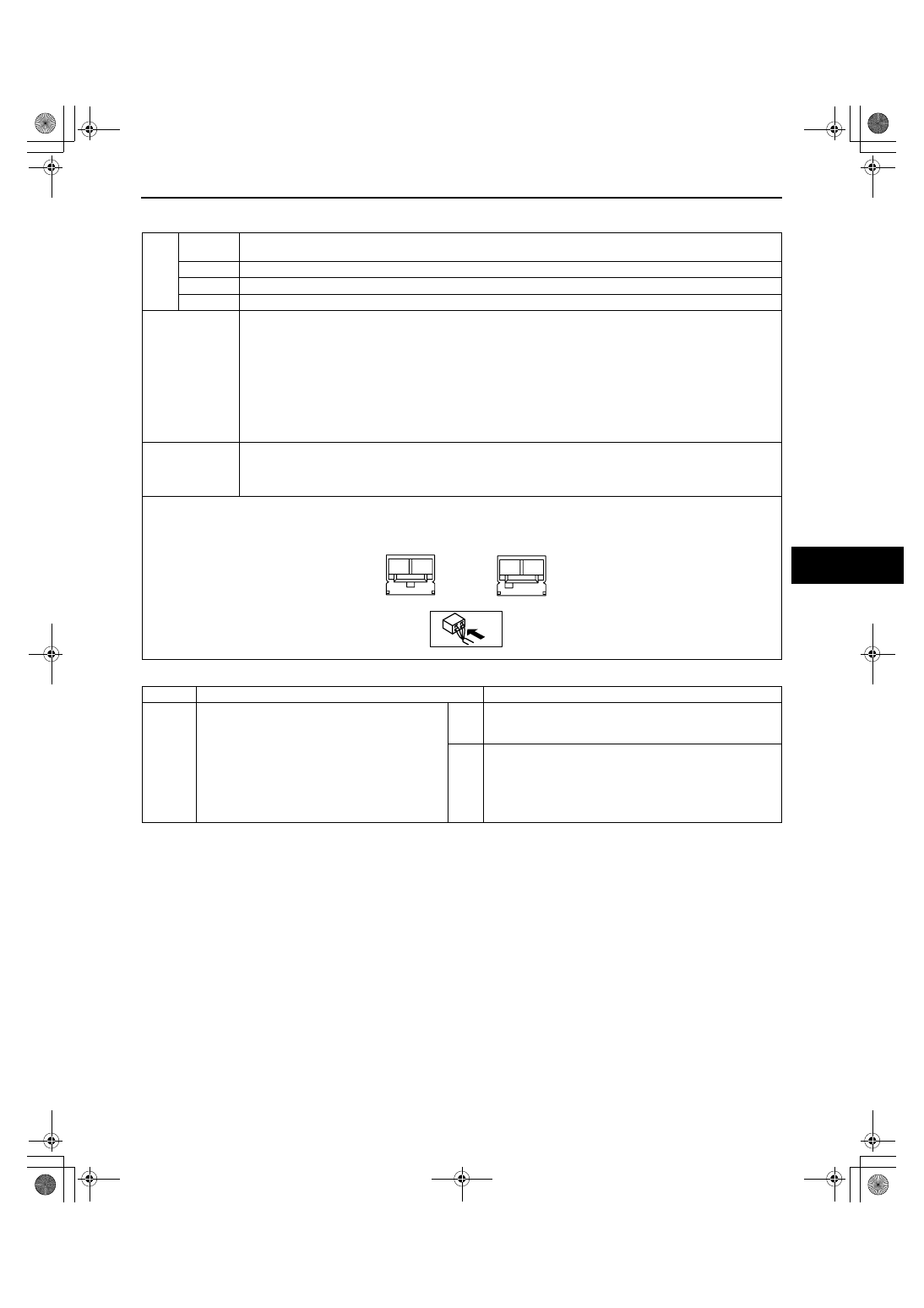
A
B
A
B
PASSENGER-SIDE AIR BAG MODULE
WIRING HARNESS-SIDE CONNECTOR
(INFLATOR NO.1)
(INFLATOR NO.2)
1871-1U-06B(08-02).fm 27 ページ 2006年3月15日 水曜日 午前11時33分