Mazda CX 7. Manual - part 304
ON-BOARD DIAGNOSTIC
08-02–11
08-02
End Of Sie
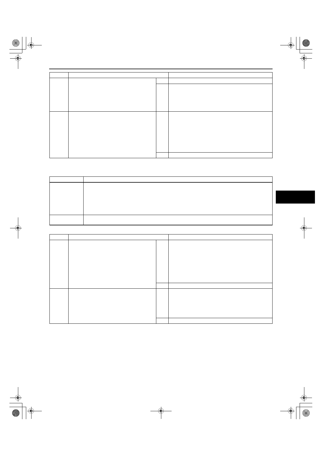
DTC B1017
id080200820000
Diagnostic procedure
End Of Sie
3
INSPECT FLOOR
• Visually inspect the installation parts of the
passenger-side seat for the following:
— Abnormal floor deformation
— Installation hole of passenger-side seat is
improperly positioned
• Is the floor normal?
Yes
Go to the next step.
No
Repair floor deformation.
• After repair, perform seat weight sensor calibration
and reperform the DTC inspection. If the DTC is
displayed even though the floor has been repaired, go
the next step. (See 08-10-12 SEAT WEIGHT
SENSOR CALIBRATION.)
4
INSPECT SEAT WEIGHT SENSOR CONTROL
MODULE
• Replace the seat weight sensor.
• After replacement, perform seat weight
sensor calibration. (See 08-10-12 SEAT
WEIGHT SENSOR CALIBRATION.)
• Reperform the DTC inspection.
• Is DTC B1013 indicated?
Yes
Replace the seat weight sensor control module.
(See 08-10-11 SEAT WEIGHT SENSOR CONTROL
MODULE REMOVAL/INSTALLATION.)
• After replacement, perform seat weight sensor
calibration and reperform the DTC inspection. If the
DTC is displayed even though the seat weight sensor
control module has been replaced, replace the SAS
control module. (See 08-10-10 SAS CONTROL
MODULE REMOVAL/INSTALLATION.)
No
DTC troubleshooting completed.
STEP
INSPECTION
ACTION
DTC B1017
Deployment prohibited because configuration is not set
DETECTION
CONDITION
Warning
• Detection conditions are for understanding the DTC outline before performing an inspection.
Performing an inspection according to only the detection conditions may cause injury due to
an operating error, or damage the system. When performing an inspection, always follow the
inspection procedure.
• SAS control module configuration has not been set.
POSSIBLE
CAUSE
• SAS control module configuration has not been set
• SAS control module malfunction
STEP
INSPECTION
ACTION
1
CONFIGURATION
• Using the M-MDS perform SAS control
module configuration. (See 08-10-11 SAS
CONTROL MODULE CONFIGURATION.)
• Turn the ignition switch to the ON position.
• Is DTC B1017 indicated?
Yes
[Present malfunction diagnosis]
• When only DTC B1017 is displayed:
— Go to the next step.
• When DTCs except B1017 are also displayed:
— Perform troubleshooting according to the
corresponding DTC inspection (except DTC
B1017).
[Past malfunction diagnosis]
• DTC troubleshooting completed.
No
DTC troubleshooting completed.
2
INSPECT SAS CONTROL MODULE
• Using the M-MDS perform SAS control
module configuration. (See 08-10-11 SAS
CONTROL MODULE CONFIGURATION.)
• Turn the ignition switch to the ON position.
• Is DTC B1017 indicated?
Yes
[Present malfunction diagnosis]
• Replace the SAS control module.
(See 08-10-10 SAS CONTROL MODULE REMOVAL/
INSTALLATION.)
[Past malfunction diagnosis]
• DTC troubleshooting completed.
No
DTC troubleshooting completed.
1871-1U-06B(08-02).fm 11 ページ 2006年3月15日 水曜日 午前11時33分