Mazda CX 7. Manual - part 290


  Index      Mazda     Mazda CX 7 - service repair manual 2007 year


Search            


Content   ..  288  289  290  291   ..


Mazda CX 7. Manual - part 290


BASIC SYSTEM 

07-11–5

07-11

.

9

8

7

5

4

3

1

2

10

19

18

17

15

14

29

28

27

21

22

30

35

34

33

31

32

6

16

20

12

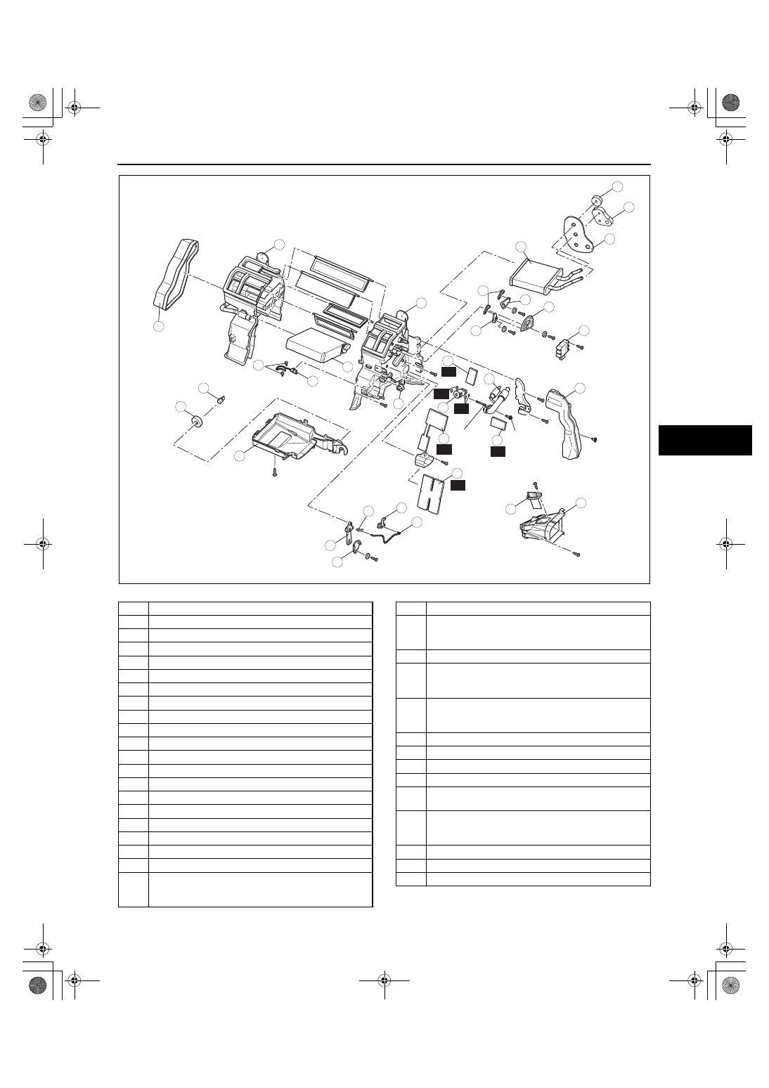
MANUAL AIR CONDITIONER

3.5—5.5
{36—56,
31—48}

26

R

25

R

R

R

24

6.8—9.8
{70—99,
61—86}

23

R

N·m {kgf·cm, in·lbf}

R

acxuuw00001834

1

Duct  (1)

2

Polyurethane protector (1)

3

Polyurethane protector (2)

4

Polyurethane protector (3)

5

Airflow mode actuator

6

Airflow mode main link

7

Airflow mode sub link (1)

8

Airflow mode sub link (2)

9

Airflow mode crank

10

Duct (2)

11

Power MOS FET (full-auto air conditioner)

12

Resistor (manual air conditioner)

13

Air mix actuator (full-auto air conditioner)

14

Air mix crank (1)

15

Air mix rod

16

Air mix link (manual air conditioner)

17

Air mix crank (2)

18

Air mix rod holder

19

Heater core

20

Wire clamp (manual air conditioner)

21

Adhesive polyurethane (1)
(See 07-11-7 Adhesive polyurethane (1) Assembly 
Note.)

22

Evaporator pipe

23

Adhesive polyurethane (3)
(See 07-11-7 Adhesive polyurethane (3) Assembly 
Note.)

24

Expansion valve

25

Adhesive polyurethane (4)
(See 07-11-7 Adhesive polyurethane (4) Assembly 
Note.)

26

Adhesive polyurethane (2)
(See 07-11-6 Adhesive polyurethane (2) Assembly 
Note.)

27

Duct (3)

28

A/C case (3)

29

A/C case (1)

30

A/C case (2)

31

Sensor clamp
(See 07-11-6 Sensor Clamp Assembly Note.)

32

Evaporator temperature sensor
(See 07-11-6 Evaporator Temperature Sensor 
Assembly Note.)

33

Evaporator

34

Drain hose

35

Polyurethane protector (4)

1871-1U-06B(07-11).fm  5 ページ  2006年3月15日 水曜日 午前11時30分

BASIC SYSTEM 

07-11–6

Sensor Clamp Assembly Note

1. Attach the sensor clamp as shown in the figure.

Evaporator Temperature Sensor Assembly Note

1. Assemble the evaporator temperature sensor as 

shown in the figure.

Adhesive polyurethane (2) Assembly Note

1. Attach the adhesive polyurethane (2) as shown in 

the figure.

2. After assembling the evaporator pipe as shown in 

the figure, attach the adhesive polyurethane (2) 
so that it adheres around the high-pressure side 
of the evaporator pipe.

SECURE AT END
OF CLAMP

RIGHT

WRONG

LOCK SECURELY

SENSOR PART

acxuuw00000696

45—55 mm
{1.8—2.1 in}

55—65 mm
{2.2—2.5 in}

SENSOR 
CLAMP

9

8

7
5

4

3

1

2

10

6

11

acxuuw00000695

CABIN
SIDE

PLATE

ADHESIVE
POLYURETHANE (2)

ATTACH ALONG
ATTACHMENT LOCATOR
RIB

ALIGN NOTCH 
WITH COVER 
ATTACHMENT 
LOCATOR

acxuuw00000697

EVAPORATOR
PIPE

PLATE

ADHESIVE
POLYURETHANE (2)

HIGH PRESSURE
SIDE PIPE

acxuuw00000698

1871-1U-06B(07-11).fm  6 ページ  2006年3月15日 水曜日 午前11時30分

BASIC SYSTEM 

07-11–7

07-11

Adhesive polyurethane (4) Assembly Note

1. Attach the adhesive polyurethane (4) so that it 

adheres around the expansion valve.

Adhesive polyurethane (3) Assembly Note

1. Attach the adhesive polyurethane (3) so that it adheres around the low-pressure side of the evaporator pipe.

Adhesive polyurethane (1) Assembly Note

1. Attach the adhesive polyurethane (1) as shown in the figure.

End Of Sie

ADHESIVE
POLYURETHANE (4)

EXPANSION 
VALVE

acxuuw00000699

ADHESIVE POLYURETHANE (3)

EVAPORATOR
PIPE

COMPLETELY ASSEMBLED

acxuuw00001835

4

3

1

2

ADHESIVE POLYURETHANE (1)

TRIANGULAR
RIB

ATTACHMENT
LOCATOR RIB

PLATE

EVAPORATOR
PIPE

COMPLETELY ASSEMBLED

ALIGN NOTCH
OF ADHESIVE
POLYURETHANE (1)
WITH TRIANGULAR RIB 
OF PLATE AND ATTACH
ALONG ATTACHMENT
LOCATOR RIB

5

acxuuw00000701

1871-1U-06B(07-11).fm  7 ページ  2006年3月15日 水曜日 午前11時30分

BASIC SYSTEM 

07-11–8

EXPANSION VALVE REMOVAL/INSTALLATION

id071100800400

1. Disconnect the negative battery cable.
2. Discharge the refrigerant from the system. (See 07-10-6 REFRIGERANT RECOVERY.) (See 07-10-2 

REFRIGERANT CHARGING.)

Caution

• If moisture or foreign material enters the refrigeration cycle, cooling ability will be lowered and 

abnormal noise will occur. Always immediately plug open fittings after removing any refrigeration 
cycle parts to keep moisture or foreign material out of the cycle.

3. Remove the insulator. (See 07-11-2 A/C UNIT REMOVAL/INSTALLATION.)
4. Disconnect the cooler hose (LO) and cooler pipe. (See 07-11-2 A/C UNIT REMOVAL/INSTALLATION.)
5. Remove the following parts:

(1) Dashboard under cover
(2) Front scuff plate inner (See 09-17-19 FRONT SCUFF PLATE REMOVAL/INSTALLATION.)
(3) Front side trim (See 09-17-18 FRONT SIDE TRIM REMOVAL/INSTALLATION.)
(4) Console panel (See 09-17-15 CONSOLE PANEL REMOVAL/INSTALLATION.)
(5) Console (See 09-17-13 CONSOLE REMOVAL/INSTALLATION.)
(6) Glove compartment (See 09-17-8 GLOVE COMPARTMENT REMOVAL/INSTALLATION.)
(7) Hood release (See 09-14-25 HOOD LATCH AND RELEASE LEVER REMOVAL/INSTALLATION.)
(8) Lower panel (See 09-17-9 LOWER PANEL REMOVAL/INSTALLATION.)
(9) Center panel (See 09-17-8 CENTER PANEL REMOVAL/INSTALLATION.)
(10)Passenger-side air bag module (See 08-10-8 SIDE AIR BAG MODULE REMOVAL/INSTALLATION.)

6. Remove the airflow mode actuator. (See 07-40-10 AIRFLOW MODE ACTUATOR REMOVAL/INSTALLATION.) 
7. Disconnect the air intake actuator connector.
8. Remove the duct (1).
9. Remove the adhesive polyurethane (1). (See 07-11-4 A/C UNIT DISASSEMBLY/ASSEMBLY.)

Caution

• Being careful not to damage the adhesive sponge rubber or adhesive polyurethane, remove 

adhesive polyurethane completely.

10. Remove the one bolt and shift the evaporator pipe. Do not allow compressor oil to spill.
11. Remove the two bolts.
12. Remove the expansion valve. Do not allow compressor oil to spill.
13. Remove the screws and plate.
14. Remove the adhesive polyurethane (2). (See 07-11-4 A/C UNIT DISASSEMBLY/ASSEMBLY.)

Caution

• Being careful not to damage the adhesive sponge rubber or adhesive polyurethane, remove 

adhesive polyurethane completely.

15. Remove the adhesive polyurethane (3). (See 07-11-4 A/C UNIT DISASSEMBLY/ASSEMBLY.)

Caution

• Being careful not to damage the adhesive sponge rubber or adhesive polyurethane, remove 

adhesive polyurethane completely.

1871-1U-06B(07-11).fm  8 ページ  2006年3月15日 水曜日 午前11時30分


Content   ..  288  289  290  291   ..