Mazda CX 7. Manual - part 288


  Index      Mazda     Mazda CX 7 - service repair manual 2007 year


Search            


Content   ..  286  287  288  289   ..


Mazda CX 7. Manual - part 288


REFRIGERANT SYSTEM 

07-10–5

07-10

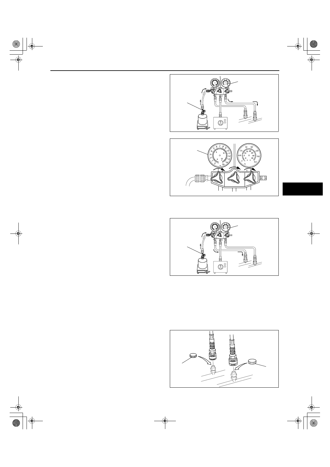
7. Open the high-pressure side valve of the manifold 

gauge and charge with refrigerant until the weight 
of refrigerant tank has decreased 250 g {8.83 oz} 
from the amount in Step 2.

8. Close the low-pressure side valve of the manifold 

gauge.

Warning

• If charging the system with refrigerant 

using service cans, running the engine 
with the high-pressure side valve open is 
dangerous. Pressure within the service 
cans will increase and the cans could 
explode, scattering metal fragments and 
liquid refrigerant that can seriously injure 
you. Therefore, do not open the high-
pressure side valve while the engine is 
running.

9. Start the engine and actuate the A/C compressor.

10. Open the low-pressure side valve of the manifold 

gauge and charge with refrigerant until the weight 
of the refrigerant tank has decreased regular 
amount from the amount in Step 2.

11. Close the low-pressure side valve of the manifold 

gauge and the valve of the refrigerant tank.

12. Stop the engine and A/C compressor.

Leak Test

1. Inspect for leakage using the a gas leak tester.

• If there is no leakage, go to Step 3.

• If leakage is found at a loose joint, tighten the joint, then go to the next step.

2. Inspect for leakage again.

• If there is no leakage after tightening the joint, go to the next step.

• If there is still leakage at the same joint, discharge the refrigerant and then repair the joint. Repeat the 

charging procedure from evacuation.

3. Disconnect the manifold gauge from the charging valves.
4. Install the caps to the charging valves.

End Of Sie

OPEN

MANIFOLD GAUGE

acxuuw00000771

MANIFOLD
GAUGE

acxuuw00000770

OPEN

MANIFOLD GAUGE

acxuuw00000773

CAP

CAP

acxuuw00000774

1871-1U-06B(07-10).fm  5 ページ  2006年3月15日 水曜日 午前11時29分

REFRIGERANT SYSTEM 

07-10–6

REFRIGERANT RECOVERY

id071000800500

Warning

• Avoid breathing air conditioning refrigerant or lubricant vapor. Exposure may irritate eyes, nose 

and throat. Also, due to environmental concerns, use service equipment certified to meet the 
requirements of SAE J2210 (R-134a recycling equipment) when draining R-134a from the air 
conditioning system. If accidental system discharge occurs, ventilate work area before resuming 
service.

1. Connect an R-134a recovery/recycling/recharging device to the vehicle and follow the device manufacturer's 

instructions.

End Of Sie

REFRIGERANT PRESSURE CHECK

id071000800600

1. Connect the manifold gauge. (See 07-10-2 REFRIGERANT SYSTEM GENERAL PROCEDURES.)
2. Start the engine and after it is warmed up, run it at a constant 1,500 rpm.
3. Set the fan speed MAX HI.
4. Turn the A/C switch on.
5. Set to RECIRCULATE mode.
6. Set the temperature control to MAX COLD.
7. Set to VENT mode.
8. Close all the doors and all the windows.
9. Measure the ambient temperature and high- and low- pressure side reading of the manifold gauge.

10. Verify that the intersection of the pressure reading of the manifold gauge and ambient temperature is in the 

shaded zone.

• If there is any malfunction, inspect the 

refrigerant system according to the 
troubleshooting chart.

End Of Sie

REFRIGERANT SYSTEM PERFORMANCE TEST

id071000800700

1. Inspect the refrigerant pressure. (See 07-10-6 REFRIGERANT PRESSURE CHECK.)
2. Place a dry-bulb thermometer in the driver-side center ventilator outlet.
3. Start the engine and after it is warmed up, run it at a constant 1,500 rpm.
4. Set the fan speed to MAX HI.
5. Turn the A/C switch on.
6. Set to RECIRCULATE mode.
7. Set the temperature control to MAX COLD.
8. Set to VENT mode.
9. Close all the doors and windows.

10. Wait until the air conditioner output temperature stabilizes.

Stabilized condition

• The A/C compressor repeatedly turns on and off at regular intervals.

11. After the blower air is stabilized, read the dry-bulb thermometer.

HIGH-PRESSURE SIDE

LOW-PRESSURE SIDE

PRESSURE READING OF MANIHOLD GA

UGE

2.0
{20, 284}

1.0
{10, 142}

0.15
{1.5, 22}

0.10
{1.0, 14}

15

{59}

20

{68}

25

{77}

30

{86}

40

{104}

35

{95}

MPa 
{kgf/cm

2

, psi}

AMBIENT TEMPERATURE

°C {°F}

10

{50}

1.5
{15, 213}

2.5
{25, 355}

acxuuw00000775

1871-1U-06B(07-10).fm  6 ページ  2006年3月15日 水曜日 午前11時29分

REFRIGERANT SYSTEM 

07-10–7

07-10

12. Verify the ambient temperature.
13. Verify that the temperature reading is in the shaded zone.

• If the there is any malfunction, inspect the 

refrigerant system according to the 
troubleshooting chart.

End Of Sie

CENTER VENTILA

T

O

R

TEMPERA

TURE

15

{59}

20

{68}

25

{77}

30

{86}

40

{104}

35

{95}

°C {°F}

°C {°F}

AMBIENT TEMPERATURE

10

{50}

1 {34}

3 {37}

5 {41}

7 {45}

9 {48}

acxuuw00000687

1871-1U-06B(07-10).fm  7 ページ  2006年3月15日 水曜日 午前11時29分


Content   ..  286  287  288  289   ..