Mazda CX 7. Manual - part 281
ON-BOARD DIAGNOSTIC
07-02–11
07-02
End Of Sie
A/C OPERATION CHECK MODE DISPLAY
id070200801400
1. Connect the M-MDS to the DLC-2 connector.
2. After the vehicle is identified, select the following
items from the initialization screen of the M-MDS.
• When using the IDS (notebook PC)
— Select the “Body” tab.
• When using the PDS (pocket PC)
— Select “All Tests and Calibrations”.
3. Select the “EATC Operation Check” from the
screen menu.
4. Verify the A/C operation check mode according to
the directions on the screen.
End Of Sie
DTC DISPLAY
id070200801500
1. Connect the M-MDS to the DLC-2 connector.
2. Shine a 60 W incandescent light from a distance
of approx. 100 mm {3.9 in} directly onto the solar
radiation sensor.
Note
• If incandescent light is not shone on the
solar radiation sensor, the climate control
unit determines a malfunction and indicates
DTC “B1260, B1261”.
3. After the vehicle is identified, select the following
items from the initialization screen of the M-MDS.
• When using the IDS (notebook PC)
— Select the “Toolbox” tab.
— Select the “Self Test”.
— Select the “Module”.
— Select the “EATC”.
• When using the PDS (pocket PC)
— Select “All Tests and Calibrations”.
— Select the “EATC”.
— Select the “Self Test”.
4. Verify the DTC according to the directions on the screen.
• If any DTCs are displayed, perform troubleshooting according to the corresponding DTC inspection.
5. After completion of repairs, clear all DTCs stored in the Climate control unit. (See 07-02-11 CLEARING DTC.)
End Of Sie
CLEARING DTC
id070200801600
1. Connect the M-MDS to the DLC-2 connector.
2. Shine a fluorescent light directly onto the solar
radiation sensor.
Note
• If fluorescent light is not shone on the solar
radiation sensor, the climate control unit
determines a malfunction and indicates DTC
“B1260, B1261”.
3. After the vehicle is identified, select the following
items from the initialization screen of the M-MDS.
• When using the IDS (notebook PC)
— Select the “Toolbox” tab.
— Select the “Self Test”.
— Select the “Module”.
— Select the “EATC”.
• When using the PDS (pocket PC)
— Select “All Tests and Calibrations”.
— Select the “EATC”.
— Select the “Self Test”.
4. Verify the DTC according to the directions on the screen.
5. Press the clear button on the DTC screen to clear the DTC.
6. Verify that no DTCs are displayed.
End Of Sie
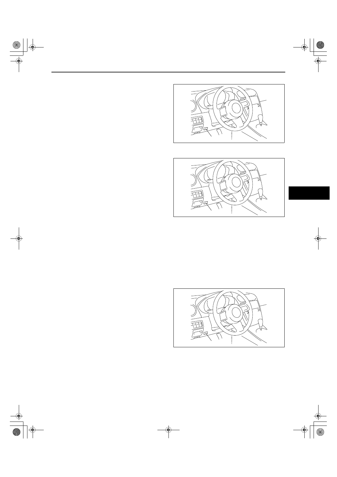
DLC-2
acxuuw00000748
DLC-2
acxuuw00000748
DLC-2
acxuuw00000748
1871-1U-06B(07-02).fm 11 ページ 2006年3月16日 木曜日 午後4時22分