Mazda CX 7. Manual - part 280
ON-BOARD DIAGNOSTIC
07-02–7
07-02
DTC B1274, B1275
id070200800800
Diagnostic Procedure
End Of Sie
DTC B1274,
B1275
Airflow mode actuator (potentiometer) system
POSSIBLE
CAUSE
• Airflow mode actuator malfunction
• Open circuit in wiring harness between climate control unit and airflow mode actuator
• Short circuit in wiring harness between climate control unit (terminal P) and airflow mode actuator
(terminal C)
STEP
INSPECTION
ACTION
1
• Inspect the airflow mode actuator. (See 07-40-11
AIRFLOW MODE ACTUATOR INSPECTION.)
• Is it normal?
Yes
Go to the next step.
No
Replace the airflow mode actuator. (See 07-40-10
AIRFLOW MODE ACTUATOR REMOVAL/
INSTALLATION.)
2
• Disconnect the climate control unit connector and
the airflow mode actuator connector.
• Is there an open circuit in the wiring harness
between the following terminals of the climate
control unit and the airflow mode actuator?
— J— B
— P— C
— C— A
Yes
Repair the wiring harness.
No
Go to the next step.
3
• Is there a short circuit to ground in the wiring
harness between climate control unit terminal P
and airflow mode actuator terminal C?
Yes
Repair the wiring harness.
No
The system is normal at present. (Clear the malfunction
from the memory.)
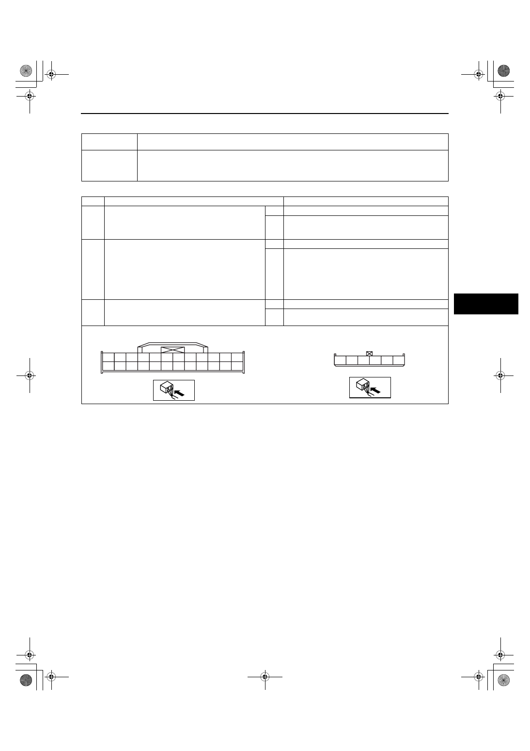
CLIMATE CONTROL UNIT CONNECTOR
AIRFLOW MODE ACTUATOR CONNECTOR
A
M
B
C
D
E
F
G
I
L
J
K
N
O
P
Q
R
S
T
U
V
W
X
A
B
C
D
F
*
H
1871-1U-06B(07-02).fm 7 ページ 2006年3月16日 木曜日 午後4時22分