Mazda CX 7. Manual - part 265


  Index      Mazda     Mazda CX 7 - service repair manual 2007 year


Search            


Content   ..  263  264  265  266   ..


Mazda CX 7. Manual - part 265


AUTOMATIC TRANSAXLE [AW6A-EL, AW6AX-EL]

05-17–49

05-17

Radiator (In Tank Oil Cooler) Installation Note

1. The automatic transaxle oil cooler flushing must be performed whenever a transaxle is removed for service 

because the existing fluid may be contaminated, and to prevent contamination of new fluid.

Note

• Flushing must be performed after installation of an overhauled or replaced transaxle.

2. Follow the instructions in the manufacturer’s publication for flushing operation.

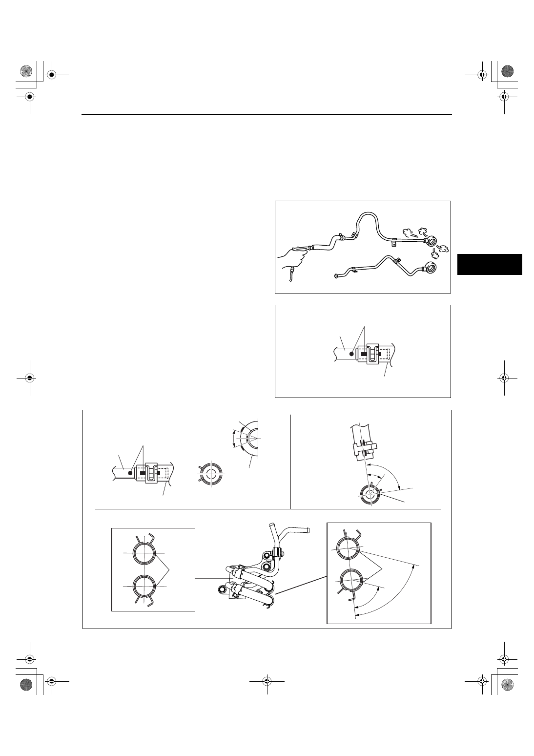
Oil Pipe, Hose Clamp, Oil Hose Installation Note

1. Apply compressed air to the cooler-side opening, 

and blow any remaining grime and foreign 
material from the cooler pipes. Compressed air 
should be applied for no less than 1 min.

2. Align the marks, and slide the oil hose onto the oil 

pipe until it is fully seated as shown in the figure.

Note

• If reusing the hose, install the new hose 

clamp exactly on the mark left by the 
previous hose camp.

3. Install the new hose clamp onto the hose.

acxuuw00000609

OIL HOSE

MARK

OIL PIPE

acxuuw00000610

OIL HOSE

MARK

OIL PIPE

OIL HOSE

OIL PIPE

MARK

MARK

HOSE CLAMP A

HOSE CLAMP B

HOSE CLAMP C

70 

°

70 

°

90 

°

45 

°

MARK

acxuuw00002342

1871-1U-06B(05-17).fm  49 ページ  2006年3月15日 水曜日 午前11時20分

AUTOMATIC TRANSAXLE [AW6A-EL, AW6AX-EL]

05-17–50

4. Verify that the hose clamp does not interfere with any other components.

End Of Sie

OIL COOLER DISASSEMBLY/ASSEMBLY[AW6A-EL, AW6AX-EL]

id051723801700

1. Disassemble in the order indicated in the table.
2. Assemble in the reverse order of disassembly.

.

R

1.8—2.2  
{19—22, 16—19}

7

4

3

6

2

5

1

N·m {kgf·cm, in·lbf}

R

acxuuw00002296

1

Mount rubber

2

Radiator outer tank (in tank oil cooler)
 (See 05-17-51 Radiator Outer Tank (In Tank Oil 
Cooler) Removal Note.)
 (See 05-17-51 Radiator Outer Tank (In Tank Oil 
Cooler) Installation Note.)

3

O-ring

4

Washer

5

Drain  cock

6

ATF cooler

7

Radiator

1871-1U-06B(05-17).fm  50 ページ  2006年3月15日 水曜日 午前11時20分

AUTOMATIC TRANSAXLE [AW6A-EL, AW6AX-EL]

05-17–51

05-17

Radiator Outer Tank (In Tank Oil Cooler) Removal Note

1. Inspect the height of the header tabs.
2. Insert the end of a medium tip screwdriver 

between the end of the header tab and the outer 
tank.

Note

• Do not open more tabs than necessary for 

tank removal.

3. Pivot the screwdriver to pry the tab away from the 

tank and repeat the procedure for each tab.

4. Remove the radiator outer tank and O-ring 

(gasket) from the core header when all of the tabs 
are opened.

Note

• If any header tabs are missing from the core, 

replace the radiator.

5. Inspect the gasket surface of the radiator core 

header to ensure it is clean and free of foreign 
material or damage.

6. Inspect the radiator outer tank for warping. If it is 

warped, replace radiator tank.

Radiator Outer Tank (In Tank Oil Cooler) Installation Note

1. Install a new O-ring and ensure it is not twisted.
2. Position the radiator tank in the original direction 

to the core using care not to scratch the tank 
sealing surface with the header tabs.

Note

• Step 3 will set jaw opening to the correct 

specification.

3. With the jaws of locking-type pliers (vise grips) 

closed and locked, turn the adjusting screw to 
position the jaws against the drill bit with the 
diameter measured (height) in the removal 
procedure 1. Tighten the lock nut on the adjusting 
screw against the handle to lock the adjustment in 
place.

RADIATOR
LOWER
TANK

HEADER TAB
HEIGHT

O-RING

acxuuw00002297

SCREWDRIVER

acxuuw00002298

O-RING

acxuuw00002299

LOCKING TYPE PLIERS
(VISE PLIERS)

LOCKNUT

ADJUSTING
SCREW

DRILL BIT

acxuuw00002300

1871-1U-06B(05-17).fm  51 ページ  2006年3月15日 水曜日 午前11時20分

AUTOMATIC TRANSAXLE [AW6A-EL, AW6AX-EL]

05-17–52

4. Squeeze the header tabs down in the order as 

shown against the lip of the radiator outer tank 
base with the locking-type pliers while rotating the 
pliers toward the tank.

5. Verify that the height of the header tabs is same 

as the height before removal.

6. Inspect for leakage from radiator. (See 01-12-6 

ENGINE COOLANT LEAKAGE INSPECTION[L3 
WITH TC].)

End Of Sie

WM: DRIVE PLATE

DRIVE PLATE REMOVAL/INSTALLATION[AW6A-EL, AW6AX-EL]

id051723802500

1. Remove the transaxle. (See05-17-29 AUTOMATIC TRANSAXLE REMOVAL/INSTALLATION[AW6A-EL, 

AW6AX-EL].)

2. Remove in the order indicated in the figure.

3. Install in the reverse order of removal.

8

7

5

4

3

6

1

2

LOCKING TYPE
PLIERS

RADIATOR LOWER

TANK

acxuuw00002301

RADIATOR
LOWER
TANK

HEADER TAB
HEIGHT

O-RING

acxuuw00002297

1

Drive plate mounting bolts
(See05-17-53 Drive Plate Mounting Bolts Removal 
Note.)

2

Backing plate

3

Drive  plate
(See05-17-53 Drive Plate Installation Note.)

SST

3

1

2

N·m {kgf·m, ft·lbf}

108—116 
{11.0—11.8, 79.7—85.5}

R

acxuuw00000611

1871-1U-06B(05-17).fm  52 ページ  2006年3月15日 水曜日 午前11時20分


Content   ..  263  264  265  266   ..