Mazda CX 7. Manual - part 228
ON-BOARD DIAGNOSTIC [AW6A-EL, AW6AX-EL]
05-02–21
05-02
Diagnostic procedure
POSSIBLE
CAUSE
• VSS malfunction
• Open circuit between VSS terminal B and TCM terminal B19
• Open circuit between VSS terminal A and TCM terminal B20
• Short to ground in wiring harness between VSS terminal B and TCM terminal B19
• Short to ground in wiring harness between VSS terminal A and TCM terminal B20
• Short to power in wiring harness between VSS terminal B and TCM terminal B19
• Short to power in wiring harness between VSS terminal A and TCM terminal B20
• Damaged connector between VSS and TCM
• TCM malfunction
STEP
INSPECTION
ACTION
1
VERIFY FREEZE FRAME DATA HAS BEEN
RECORDED
• Has the FREEZE FRAME DATA been
recorded?
Yes
Go to the next step.
No
Record the FREEZE FRAME DATA on the repair order,
then go to the next step.
2
VERIFY RELATED REPAIR INFORMATION
AVAILABILITY
• Verify related Service Bulletins and/or on-line
repair information availability.
• Is any related repair information available?
Yes
Perform repair or diagnosis according to the available
repair information.
• If the vehicle is not repaired, go to the next step.
No
Go to the next step.
3
INSPECT TERMINAL COUPLE COMPONENT
FOR POOR CONNECTION
• Turn the ignition switch to the LOCK position.
• Remove the TCM.
(See 05-17-25 TCM REMOVAL/
INSTALLATION[AW6A-EL, AW6AX-EL].)
• Inspect for poor connection (such as damaged/
pulled-out pins, corrosion).
• Are terminals normal?
Yes
Go to the next step.
No
Replace the couple component, then go to Step 8.
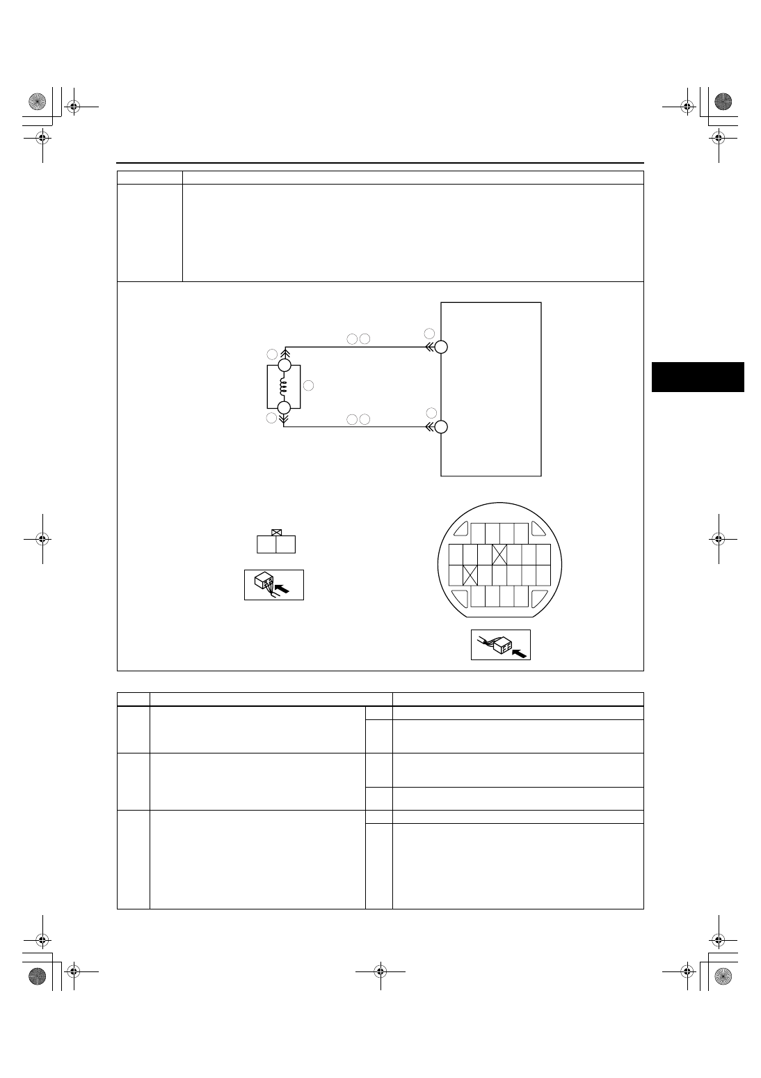
DTC P0722
Vehicle speed sensor (VSS) circuit malfunction (open circuit/short circuit)
B
A
B19
B20
A
B
VSS
VSS WIRING HARNESS-SIDE CONNECTOR
7
6
3
4
5
5
3
7
6
TCM
COUPLE COMPONENT CONNECTOR
COUPLE COMPONENT
B20
B19
(+)
(-)
1871-1U-06B(05-02).fm 21 ページ 2006年3月15日 水曜日 午前11時18分