Mazda CX 7. Manual - part 216
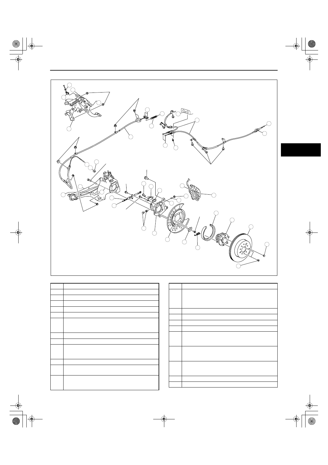
PARKING BRAKE SYSTEM
04-12–9
04-12
8. Inspect the rear wheel alignment. (See 02-11-4 REAR WHEEL ALIGNMENT.)
.
11
13
16
15
18
19
20
14
17
21
24
23
22
7
2
10
8
H
H
D
78.4—101.9
{8.0—10.3, 57.9—75.1}
18.6—25.5
{1.90—2.60,
13.8—18.8}
18.6—25.5
{1.90—2.60, 13.8—18.8}
18.6—25.5
{1.90—2.60,
13.8—18.8}
18.6—25.5
{1.90—2.60,
13.8—18.8}
98—120
{10—12, 73—88}
A
B
E
E
C
F
G
A
B
4
3
1
6
C
N·m {kgf·m, ft·lbf}
9.8—14.7
N·m
{100—149 kgf·cm,
87—130 in·lbf}
12
3—6
N·m
{40—60 kgf·cm,
30—50 in·lbf}
3—6
N·m
{40—60 kgf·cm,
30—50 in·lbf}
7.8—10.8
N·m
{80—110 kgf·cm,
70—95 in·lbf}
9
5
G
D
F
18.6—25.5
{1.90—2.60,
13.8—18.8}
20
acxuuw00001873
1
Parking brake switch connector
2
Adjusting nut
3
Parking brake switch
4
Parking brake pedal
5
Spring
6
Clip
7
End cable
(See 04-12-10 End Cable Removal Note.)
(See 04-12-13 End Cable Installation Note.)
8
Rear parking brake cable
9
Front Parking brake cable, equalizer
10
Brake caliper component
(See 04-12-10 Brake Caliper Component Removal
Note)
11
Plug
12
Screw
(See 04-12-12 Disc Plate, Screw Installation Note)
13
Disc plate
(See 04-12-10 Disc Plate Removal Note)
(See 04-12-12 Disc Plate, Screw Installation Note)
14
Spring
15
Parking brake shoe
(See 04-12-11 Parking Brake Shoe Removal Note)
(See 04-12-11 Parking Brake Shoe Installation
Note)
16
Rear wheel hub component
17
Shoe stopper
18
Backing plate
19
Parking brake plate
20
Adjuster bolt and nut, tappet
(See 04-12-11 Operation lever, Pin, Adjuster Bolt
and Nut, Tappet Installation Note)
21
Pin
(See 04-12-11 Operation lever, Pin, Adjuster Bolt
and Nut, Tappet Installation Note.)
22
Operation lever
(See 04-12-11 Operation lever, Pin, Adjuster Bolt
and Nut, Tappet Installation Note.)
23
Plate
24
Dust boot
1871-1U-06B(04-12).fm 9 ページ 2006年3月15日 水曜日 午前11時15分