Mazda CX 7. Manual - part 213


  Index      Mazda     Mazda CX 7 - service repair manual 2007 year


Search            


Content   ..  211  212  213  214   ..


Mazda CX 7. Manual - part 213


CONVENTIONAL BRAKE SYSTEM 

04-11–23

04-11

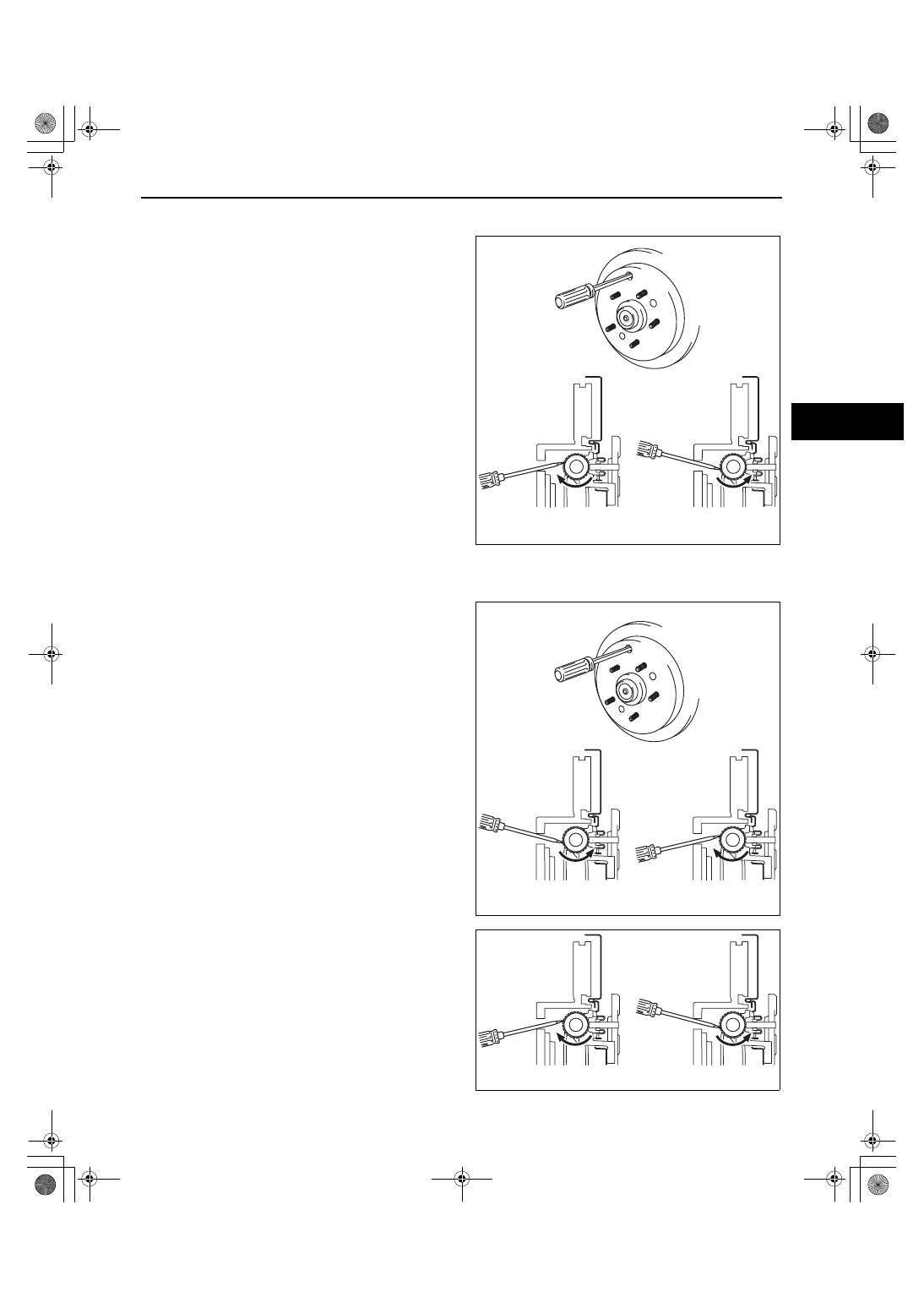
Disc Plate Removal Note

1. If any disc plate is difficult to remove, perform the following steps to remove it.

(1) Insert a flathead screwdriver into the service 

hole and turn the adjuster in the direction of 
the arrow to compress the parking brake 
shoe.

(2) Remove the disc plate.

Disc Plate, Screw Installation Note

1. Install the disc plate and the screws.
2. Perform the following steps to adjust the shoe clearance after installing the disc plate and the screws.

(1) Insert a flathead screwdriver into the service 

hole and turn the adjuster in the direction of 
the arrow to expand the parking brake shoe 
until the disc plate cannot rotate.

(2) Return the adjuster 13—17 notches in the 

direction of the arrow.

Note

• Shoe clearance can be adjusted to 0.15 mm 

{0.006 in} by returning the adjuster 15 
notches
.

(3) Rotate the disc plate and make sure it does 

not drag.

LEFT SIDE

RIGHT SIDE

acxuuw00001072

LEFT SIDE

RIGHT SIDE

acxuuw00001073

LEFT SIDE

RIGHT SIDE

acxuuw00001074

1871-1U-06B(04-11).fm  23 ページ  2006年3月15日 水曜日 午前11時13分

CONVENTIONAL BRAKE SYSTEM 

04-11–24

Caliper Installation Note

1. Push the piston fully inward using the SST.
2. Install the caliper.

End Of Sie

WM: DISC PAD (REAR)

DISC PAD (REAR) REPLACEMENT

id041100800300

1. Remove in the order indicated in the table.
2. Install in the reverse order of removal.
3. After installation, depress the brake pedal a few times, rotate the wheel by hand, and verify that the brake does 

not drag.

.

End Of Sie

WM: CALIPER (REAR)

49 0221 600C

acxuuw00001075

2

3

1

6

SST

4

4

5

A

A

5

21.6—31.4 

{2.21—3.20,
 16.0—23.1}

N·m {kgf·m, ft·lbf}

acxuuw00001931

1

Clip

2

Bolt

3

Caliper
(See 04-11-22 REAR BRAKE (DISC) REMOVAL/
INSTALLATION)

4

Disc pad

5

Shim

6

Guide plate

1871-1U-06B(04-11).fm  24 ページ  2006年3月15日 水曜日 午前11時13分

CONVENTIONAL BRAKE SYSTEM 

04-11–25

04-11

CALIPER (REAR) DISASSEMBLY/ASSEMBLY

id041100800600

1. Disassemble in the order indicated in the table.

2. Assemble in the reverse order of removal.

Piston Disassembly Note

Warning

• When compressed air is blown into the caliper body, injury to a finger or other part from pinching 

could result from the piston springing up. When blowing in compressed air, do not place your 
fingers between the piston and caliper body when performing the work.

Caution

• The piston could be damaged if blown out with great force. Blow the compressed air slowly to 

prevent the piston from suddenly popping out.

1. Place a piece of wood in the caliper, then blow 

compressed air through the hole to force the 
piston out of the caliper.

End Of Sie

1

Bleeder cap

2

Bleeder screw

3

Piston
(See 04-11-25 Piston Disassembly Note)

4

Dust  seal

5

Piston  seal

6

Caliper

GREASEGREASE

GREASEGREASE

GREASEGREASE

SST

R

*

49 0259 770B

BRAKE
FLUID

SST

*

2

R

5

4

3

1

RUBBER GREASE

6

6.9—9.8

 N·m 

{71—99 kgf·cm,
 62—86 in·lbf}

acxuuw00001076

WOOD PLATE

acxuuw00001077

1871-1U-06B(04-11).fm  25 ページ  2006年3月15日 水曜日 午前11時13分


Content   ..  211  212  213  214   ..