Mazda CX 7. Manual - part 211


  Index      Mazda     Mazda CX 7 - service repair manual 2007 year


Search            


Content   ..  209  210  211  212   ..


Mazda CX 7. Manual - part 211


CONVENTIONAL BRAKE SYSTEM 

04-11–15

04-11

The disc plate is deformed by heat.
Repeated panic braking may raise the temperature in some portions of disc plate by approx. 1,000 

°C {1,832 °F}

This results in deformed disc plate.

Due to corrosion, the thickness and friction coefficient of disc plate change.
If a vehicle is parked under damp conditions for a long time, corrosion occurs on the friction surface of disc plate.
The thickness of corrosion is uneven and sometimes appears like a wave pattern, which changes the friction 
coefficient and causes a reaction force.

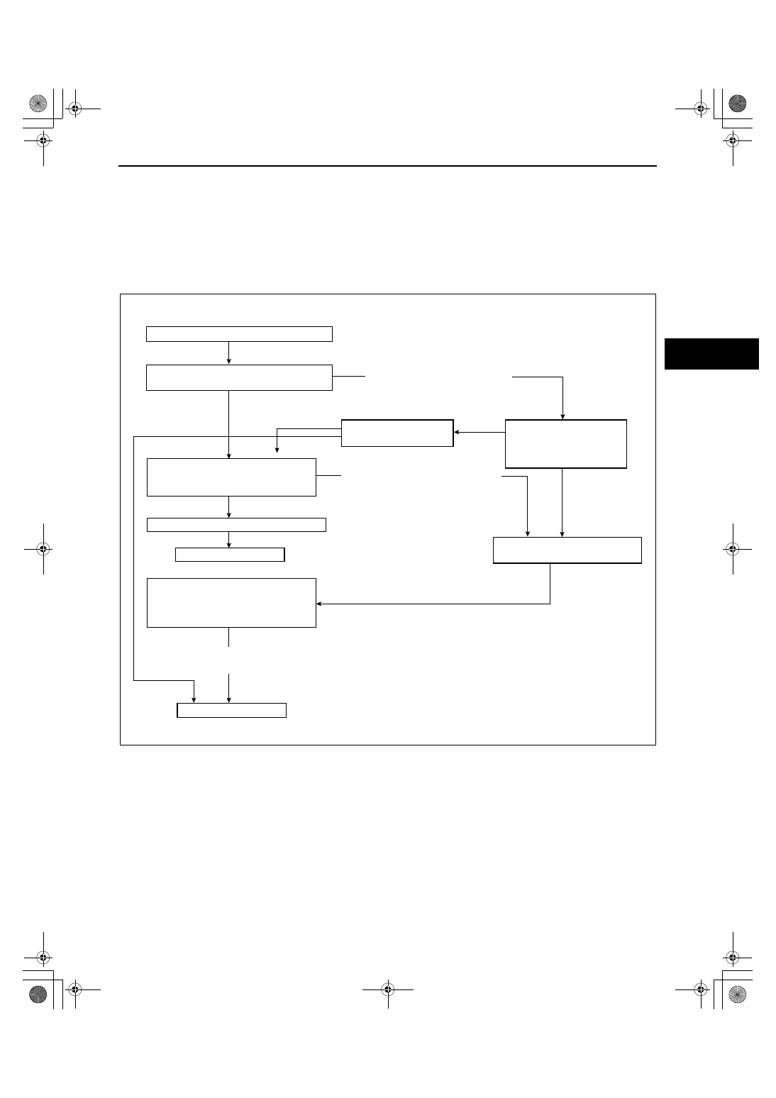
Inspection and repair procedure

Lateral runout inspection

1. To secure the disc plate and the hub, tighten the hub nuts upside down or insert a washer (thickness 10 mm 

{0.39 in} with an inner diameter more than 12 mm {0.47 in}) between the hub bolt and the hub nut.

Note

• The component parts of the SST (49 B017 001 or 49 G019 003) can be used as a suitable washer.

2. After tightening all the hub nuts to the same torque, put the dial gauge on the friction surface of disc plate 10 

mm {0.39 in} from the disc plate edge.

3. Rotate the disc plate one time and measure the runout.

Front disc plate runout limit

0.05 mm {0.002 in}

Occurs

Does not
occur

Confirm customer

,

s complaint

Less than
0.05 mm
{0.002 in}

Less than 0.015 mm {0.0005 in}

On-the-car type lathe (less than
0.015 mm {0.0005 in}).

More than 0.015 mm {0.0005 in}

More than 0.05 mm {0.002 in}

More than
0.05 mm
{0.002 in}

Less than 
0.05 mm
{0.002 in}

Perform lateral runout inspection.
(Refer to Lateral Runout Inspection.)

Verify whether brake
judder occurs or not.

Machine the disc plate using
on-the-car type lathe.

Remove disc plate and
reinstall in other phase.
Perform lateral runout
inspection again.

Perform thickness variation
inspection (Refer to the
following.)

Secure the disc plate by
tightening all hub nuts to the
same torque, and measure lateral
runout.

Work is completed.

Confirm customer's complaint again.

Work is completed.

acxuuw00001079

1871-1U-06B(04-11).fm  15 ページ  2006年3月15日 水曜日 午前11時13分

CONVENTIONAL BRAKE SYSTEM 

04-11–16

Thickness variation inspection

1. Clean the disc plate-to-pad friction surface using a brake cleaner.
2. Measure the points indicated in the illustration using a caliper (micrometer).
3. Subtract the minimum value from the maximum. 

• If the result is not within specification, machine the disc plate using a lathe.

Thickness variation limit

0.015 mm {0.0005 in}

Warning

• Do not exceed minimum disc plate 

thickness.

Disc Plate Thickness Inspection

Caution

• Excessive runout may result if the disc plate is removed from the vehicle then machined. Machine 

the disc plate while installed on the vehicle.

1. Measure the thickness of the disc plate.

• If the thickness is not within the specification, replace the disc plate.

Minimum front disc plate thickness

26 mm {1.03 in}

Minimum front disc plate thickness after machining using a brake lathe on-vehicle

26.8 mm {1.06 in}

Disc Pad Thickness Inspection

1. Jack up the front of the vehicle and support it with safety stands.
2. Remove the wheels.
3. Verify the remaining thickness of the pads.

• Replace the pads as a set: right and left wheels, if either one is at or less than the minimum thickness.

Minimum front disc pad thickness

2.0 mm {0.08 in}

End Of Sie

acxuuw00001386

ampjjw00003083

1871-1U-06B(04-11).fm  16 ページ  2006年3月15日 水曜日 午前11時13分

CONVENTIONAL BRAKE SYSTEM 

04-11–17

04-11

FRONT BRAKE (DISC) REMOVAL/INSTALLATION

id041100800900

1. Remove in the order indicated in the table.
2. Install in the reverse order of removal.
3. After installation, add brake fluid, bleed the air, and inspect for fluid leakage. (See 04-11-3 AIR BLEEDING.)
4. After installation, depress the brake pedal a few times, rotate the wheel by hand, and verify that the brake does 

not drag.

.

Caliper Installation Note

1. Push the piston fully inward using the SST.
2. Install the caliper.

End Of Sie

WM: DISC PAD (FRONT)

R

GREASEGREASE

GREASEGREASE

GREASEGREASE

GREASEGREASE

GREASEGREASE

GREASEGREASE

4

9

D

3

C

C

7

2

R

R

5

8

7

D

6

SST

83.3—93.1 
{8.50—9.49,
 61.5—68.6}

21.6—29.4 
{2.21—2.99,
 16.0—21.6}

107.8—127.4 
{11.00—12.99,
 79.51—93.96}

4

6

A

A

A

A

B

B

A

ANTI-RATTLE 
BRAKE GREASE

GREASEGREASE

B

RUBBER GREASE

GREASEGREASE

10

10

11

12

1

9.8—14.7 N·m 
{100—149 kgf·cm,
 87—130 in·lbf}

N·m {kgf·m, ft·lbf}

acxuuw00001081

1

Brake hose

2

Slide pin bolt

3

Caliper
(See 04-11-17 Caliper Installation Note.)

4

Disc pad

5

Pad wear indicator

6

Shim

7

Guide plate

8

Bolt

9

Mounting support

10

Dust boot

11

Screw

12

Disc plate

49 0221 600C

WOOD PLATES

acxuuw00001082

1871-1U-06B(04-11).fm  17 ページ  2006年3月15日 水曜日 午前11時13分

CONVENTIONAL BRAKE SYSTEM 

04-11–18

DISC PAD (FRONT) REPLACEMENT

id041100800700

1. Remove in the order indicated in the table.
2. Install in the reverse order of removal.
3. After installation, depress the brake pedal a few times, rotate the wheel by hand, and verify that the brake does 

not drag.

.

End Of Sie

WM: CALIPER (FRONT)

CALIPER (FRONT) DISASSEMBLY/ASSEMBLY

id041100801000

1. Disassemble in the order indicated in the table.

2. Assemble in the reverse order of removal.

GREASEGREASE

GREASEGREASE

GREASEGREASE

GREASEGREASE

5

6

3

5

1

2

A

A

SST

6

4

ANTI-RATTLE 
BRAKE GREASE

83.3—93.1 
{8.50—9.49,
 61.5—68.6}

N·m {kgf·m, ft·lbf}

acxuuw00001078

1

Slide pin bolt

2

Caliper
(See 04-11-17 FRONT BRAKE (DISC) REMOVAL/
INSTALLATION.)

3

Disc pad

4

Pad wear indicator

5

Shim

6

Guide plate

1

Bleeder cap

2

Bleeder screw

3

Piston
(See 04-11-19 Piston Disassembly Note.)

4

Dust seal

5

Piston seal

6

Caliper

R

R

GREASEGREASE

GREASEGREASE

GREASEGREASE

SST

SST

*

SST

*

5.9—9.8 {61—99, 53—86}

49 0259 770B

BRAKE
FLUID

2

1

5

4

3

RUBBER GREASE

6

N·m {kgf·cm, in·lbf}

acxuuw00001083

1871-1U-06B(04-11).fm  18 ページ  2006年3月15日 水曜日 午前11時13分


Content   ..  209  210  211  212   ..