Mazda CX 7. Manual - part 201
ON-BOARD DIAGNOSTIC
04-02–19
04-02
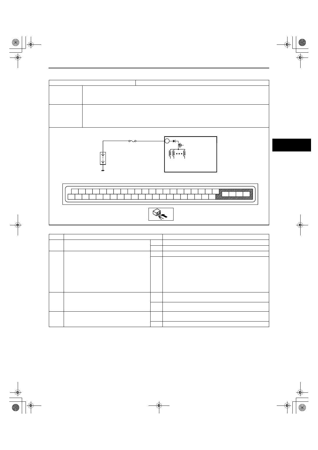
DTC C1186, C1266
id040200801300
Diagnostic procedure
End Of Sie
DTC
C1186, C1266
Valve relay system
DETECTION
CONDITION
• C1186
— DSC HU/CM internal valve relay remains OFF when valve relay ON is commanded.
• C1266
— DSC HU/CM internal valve relay remains ON (stuck) when valve relay OFF is commanded.
POSSIBLE
CAUSE
• ABS 2 20A fuse malfunction
• Open circuit or short to ground in the wiring harness between the battery and the DSC HU/CM terminal
C
• Open or short circuit in the DSC HU/CM internal valve relay, or stuck valve relay
• Poor connection at connectors (female terminal)
STEP
INSPECTION
ACTION
1
INSPECT DSC FUSE CONDITION
• Is the ABS 2 20A fuse normal?
Yes
Go to the next step.
No
Replace the fuse, then go to Step 3.
2
INSPECT VALVE RELAY POWER SUPPLY
FOR OPEN CIRCUIT
• Turn the ignition switch off.
• Disconnect DSC HU/CM connector.
• Turn the ignition switch to the ON position
(engine off).
• Measure voltage between DSC HU/CM
terminal C (harness-side) and ground.
• Is voltage B+?
Yes
Go to the next step.
No
Repair or replace the wiring harness for open circuit
between battery positive terminal and DSC HU/CM terminal
C, then go to the next step.
3
VERIFY TROUBLESHOOTING COMPLETED
• Clear the DTC from the memory.
(See 04-02-3 ON-BOARD DIAGNOSIS.)
• Is the same DTC present?
Yes
Replace the DSC HU/CM, then go to next step.
(See 04-15-6 DSC HU/CM REMOVAL/INSTALLATION.)
No
Go to the next step.
4
VERIFY AFTER REPAIR PROCEDURE
• Are any other DTCs present?
Yes
Go to the applicable DTC inspection.
(See 04-02-3 ON-BOARD DIAGNOSIS.)
No
DTC troubleshooting completed.
DSC HU/CM
C
BATTERY
ABS 2 20A
A
B
C
D
F
I
L
O
R
U
X
E
H
Q
T
W
Z
G
J
M
P
S
V
Y
K
N
AA
AB
AC
AD
AE
AF
AG
AH
AI
AJ
AK
AL
AM
AN
AO
AP
AQ
AR
AS
AT
DSC HU/CM WIRING HARNESS-SIDE CONNECTOR
1871-1U-06B(04-02).fm 19 ページ 2006年3月15日 水曜日 午前11時12分