Mazda CX 7. Manual - part 191
TRANSFER
03-16–1
03-16
03-16
TRANSFER
TRANSFER LOCATION INDEX . . . . . . . 03-16–1
TRANSFER OIL INSPECTION . . . . . . . . 03-16–2
TRANSFER OIL REPLACEMENT . . . . . 03-16–2
TRANSFER OIL SEAL
REPLACEMENT . . . . . . . . . . . . . . . . . . 03-16–2
TRANSFER OIL COOLER
REMOVAL/INSTALLATION . . . . . . . . . . 03-16–3
TRANSFER
REMOVAL/INSTALLATION . . . . . . . . . . 03-16–3
No.1 Engine Mount Installation Note. . . 03-16–5
End of Toc
WM: TRANSFER
TRANSFER LOCATION INDEX
id031600800100
.
End Of Sie
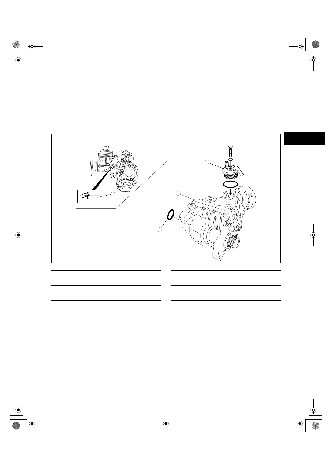
1
2
3
4
acxuuw00002322
1
Transfer oil
(See 03-16-2 TRANSFER OIL INSPECTION.)
(See 03-16-2 TRANSFER OIL REPLACEMENT.)
2
Transfer oil seal
(See 03-16-2 TRANSFER OIL SEAL
REPLACEMENT.)
3
Transfer oil cooler
(See 03-16-3 TRANSFER OIL COOLER
REMOVAL/INSTALLATION.)
4
Transfer
(See 03-16-3 TRANSFER REMOVAL/
INSTALLATION.)
1871-1U-06B(03-16).fm 1 ページ 2006年3月15日 水曜日 午前11時9分