Mazda CX 7. Manual - part 181


  Index      Mazda     Mazda CX 7 - service repair manual 2007 year


Search            


Content   ..  179  180  181  182   ..


Mazda CX 7. Manual - part 181


DRIVE SHAFT 

03-13–11

03-13

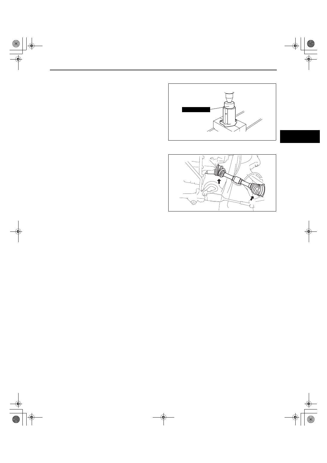
Dust Seal Assembly Note

1. Apply grease to the new dust seal lip.
2. Install the new dust seal using a press and the 

SSTs.
Substitution SST

• 49 G028 203

Outer diameter: 64 mm {2.5 in} or more
Inner diameter: 57.6— 59.0 mm {2.27— 2.32 
in}
Inner depth: 38.5 mm {1.52 in} or more

End Of Sie

WM: DRIVE SHAFT

FRONT DRIVE SHAFT PRE-INSPECTION

id031300800200

1. Inspect the dust boot on the drive shaft for cracks, 

damage, leaking grease, and looseness in the 
boot band.

2. Inspect the drive shaft for bends, cracks, and 

wear in the joint or splines.

• Repair or replace the drive shaft or boot/band 

as necessary.

End Of Sie

49 G028 203

acxuuw00001358

A6E0313W033

1871-1U-06B(03-13).fm  11 ページ  2006年3月15日 水曜日 午前11時6分

DRIVE SHAFT 

03-13–12

FRONT DRIVE SHAFT REMOVAL/INSTALLATION

id031300800300

Caution

• Performing the following procedures without first removing the ABS wheel-speed sensor may 

possibly cause an open circuit in the harness if it is pulled by mistake. Before performing the 
following procedures, remove the ABS wheel-speed sensor (axle side) and fix it to an appropriate 
place where the sensor will not be pulled by mistake while the vehicle is being serviced.

1. Remove the side cover and under cover.
2. Remove the front ABS wheel-speed sensor. (See 04-15-11 FRONT ABS WHEEL-SPEED SENSOR 

REMOVAL/INSTALLATION.)

3. Remove in the order indicated in the table.
4. Install in the reverse order of removal.

.

A

A

5

3

6

1

2

5

6

SST

R

R

R

R

47.0—59.0
{4.80—6.01,
34.7—43.5}

43.1—58.8
{4.40—5.99,
31.8—43.3}

42.3—60.1
{4.32—6.12,
31.2—44.3}

235.2—274.4
{23.99—27.98,
173.5—202.3}

N·m {kgf·m, ft·lbf}

4

acxuuw00001222

1

Locknut
(See 03-13-13 Locknut Removal Note.)
(See 03-13-14 Locknut Installation Note.)

2

Tie-rod end ball joint
(See 02-13-10 FRONT CROSSMEMBER 
REMOVAL/INSTALLATION.)

3

Front stabilizer control link (lower side)

4

Front lower arm ball joint

5

Front drive shaft 
(See 03-13-13 Front Drive Shaft Removal Note.)
(See 03-13-14 Front Drive Shaft Installation Note.)

6

Clip
(See 03-13-13 Clip Installation Note.)

1871-1U-06B(03-13).fm  12 ページ  2006年3月15日 水曜日 午前11時6分

DRIVE SHAFT 

03-13–13

03-13

Locknut Removal Note

1. Lock the hub by applying the brakes.
2. Knock the crimped portion of the locknut outward 

using a small chisel and a hammer.

3. Remove the locknut.

Front Drive Shaft Removal Note

1. Install a spare nut onto the drive shaft so that the nut is flush with the end of the drive shaft.
2. Tap the nut with a copper hammer to loosen the 

drive shaft from the front wheel hub.

3. Separate the drive shaft from the wheel hub.

Caution

• The sharp edges of the drive shaft can 

slice or puncture the oil seal. Be careful 
when removing the drive shaft from the 
transaxle.

4. Separate the left side drive shaft from the 

transaxle by prying with a bar inserted between 
the outer ring and the transaxle, as shown in the 
figure.

5. Separate the right side drive shaft from the joint 

shaft by tapping on a bar inserted between them.

Clip Installation Note

1. Install a new clip onto the drive shaft with the opening facing upward. Ensure that the diameter of the clip does 

not exceed the specification on installation.

acxuuw00001114

acxuuw00001115

acxuuw00001223

acxuuw00001224

1871-1U-06B(03-13).fm  13 ページ  2006年3月15日 水曜日 午前11時6分

DRIVE SHAFT 

03-13–14

2. After installation, measure the outer diameter. If it 

exceeds the specification, repeat Steps 1— 2 
using a new clip.

Clip outer diameter specification

LH: 33.5 mm {1.32 in}
RH (joint shaft): 34.0 mm {1.34 in}

Front Drive Shaft Installation Note

Caution

• The sharp edges of the drive shaft can slice or puncture the oil seal. Be careful when installing the 

drive shaft to the transaxle.

• The oil seals are damaged easily if this 

procedure is not done correctly.

Left side

1. Insert the drive shaft into the wheel hub.
2. Apply transaxle oil to the oil seal lip.
3. Push the drive shaft into the transaxle.
4. After installation, pull the transaxle side outer ring forward to confirm that the drive shaft is securely held by the 

clip.

Right side

1. Insert the drive shaft into the wheel hub.
2. Insert the drive shaft into the joint shaft.
3. After installation, pull the transaxle side outer ring forward to confirm that the drive shaft is securely held by the 

clip.

Locknut Installation Note

1. Install a new locknut and stake it as shown.

End Of Sie

OUTER
DIAMETER

OPENING

CLIP

acxuuw00001225

acxuuw00001226

0.5 mm {0.02 in} OR MORE

acxuuw00001128

1871-1U-06B(03-13).fm  14 ページ  2006年3月15日 水曜日 午前11時6分


Content   ..  179  180  181  182   ..