Mazda CX 7. Manual - part 180


  Index      Mazda     Mazda CX 7 - service repair manual 2007 year


Search            


Content   ..  178  179  180  181   ..


Mazda CX 7. Manual - part 180


DRIVE SHAFT 

03-13–7

03-13

Dust Seal (Differential Side) Disassembly Note

1. Remove the dust seal using a flathead screwdriver.

Bearing Disassembly Note

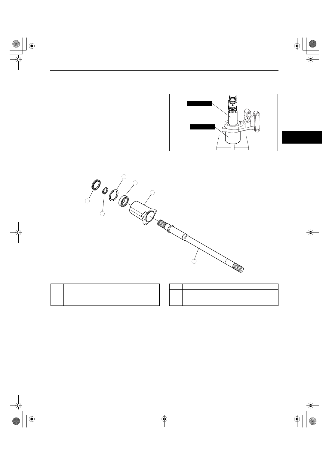
1. Remove the bearing using a press and the SSTs.

Substitution SST

• 49 B014 001

Outer diameter: 47— 55 mm {1.9— 2.1 in}

• 49 W034 301

Inner diameter: 67.5— 72 mm {2.7— 2.8 in}
Inner depth: 16 mm {0.63 in} or more
Plate thickness: 1 mm {0.04 in} or more

End Of Sie

JOINT SHAFT DISASSEMBLY[AWD]

id0313008010a5

1. Disassemble in the order indicated in the table.

.

Dust Seal Disassembly Note

1. Remove the dust seal using a flathead screwdriver.

49 W034 301

49 B014 001

acxuuw00001303

5

4

3

6

1

2

acxuuw00001353

1

Dust  seal
(See 03-13-7 Dust Seal Disassembly Note)

2

Clip

3

Snap ring

4

Joint shaft

5

Bearing
(See 03-13-8 Bearing Disassembly Note)

6

Bearing housing

1871-1U-06B(03-13).fm  7 ページ  2006年3月15日 水曜日 午前11時6分

DRIVE SHAFT 

03-13–8

Bearing Disassembly Note

1. Remove the bearing from the joint shaft using a 

press.

End Of Sie

JOINT SHAFT ASSEMBLY[2WD]

id0313008011a3

1. Assemble in the order indicated in the table.

.

Bearing Assembly Note

1. Install the new bearing using a press and the 

SSTs.
Substitution SST

• 49 B025 004

Outer diameter: 61 mm {2.4 in}
Inner diameter: 46 mm {1.8 in}

BEARING

acxuuw00001354

5

4

3

6

1

2

SST

SST

8

7

R

GREASEGREASE

R

GREASEGREASE

SST

R

R

R

SST

7.8—10.8 N·m
{80—110 kgf·cm, 69.1—95.5 in·lbf}

acxuuw00001348

1

Bearing housing

2

Bearing
(See 03-13-8 Bearing Assembly Note)

3

Snap ring

4

Dust seal (differential side)
(See 03-13-9 Dust Seal (Differential Side) Assembly 
Note)

5

Dust seal (axle side)
(See 03-13-9 Dust Seal (Axle Side) Assembly Note)

6

Joint shaft
(See 03-13-9 Joint Shaft Assembly Note)

7

Snap ring

8

Cover

49 G030 797

49 B025 004

acxuuw00001349

1871-1U-06B(03-13).fm  8 ページ  2006年3月15日 水曜日 午前11時6分

DRIVE SHAFT 

03-13–9

03-13

Dust Seal (Differential Side) Assembly Note

1. Apply grease to the new dust seal lip.
2. Install the dust seal (differential side) using a 

press and the SSTs.
Substitution SST

• 49 B025 004

Outer diameter: 58— 59.8 mm {2.2— 2.3 in} 
or less
Inner diameter: 53 mm {2.1 in} or more
Inner depth: 7.5 mm {0.30 in} or more

Dust Seal (Axle Side) Assembly Note

1. Apply grease to the new dust seal lip.
2. Install the dust seal (axle side) using a press and 

the SSTs.
Substitution SST

• 49 G028 203

Outer diameter: 64 mm {2.5 in} or more
Inner diameter: 57.6— 59.0 mm {2.27— 2.32 
in}
Inner depth: 6.8 mm {0.27 in} or more

• 49 W034 301

Inner diameter: 67.5— 72.0 mm {2.66— 2.83 
in}
Inner depth: 8.5 mm {0.33 in} or more
Plate thickness: 1 mm {0.04 in} or more

Joint Shaft Assembly Note

1. Install the joint shaft using a press and the SST.

Substitution SST

• 49 F401 337A

Outer diameter: 39— 42 mm {1.5— 1.6 in}
Inner diameter: 35.2 mm {1.4 in} or more
Inner depth: 48.5 mm {1.91 in} or more

End Of Sie

49 G030 797

49 B025 004

acxuuw00001349

49 W034 301

49 G028 203

acxuuw00001350

49 F401 337A

JOINT SHAFT

acxuuw00001351

1871-1U-06B(03-13).fm  9 ページ  2006年3月15日 水曜日 午前11時6分

DRIVE SHAFT 

03-13–10

JOINT SHAFT ASSEMBLY[AWD]

id0313008011a5

1. Assemble in the order indicated in the table.

.

Bearing Assembly Note

1. Install the new bearing to the bracket.

Note

• When the bearing is not installed to the 

bracket by hand, install it using the SST.

Substitution SST

• 49 V001 525

Outer diameter: 58— 61 mm {2.3— 2.4 in}

Joint Shaft Assembly Note

1. Install the joint shaft using a press and the SST.

Substitution SST

• 49 V001 525

Outer diameter: 58— 61 mm {2.3— 2.4 in}
Inner diameter: 35.2— 39.6 mm {1.39— 1.55 
in}
Inner depth: 48.5 mm {1.91 in} or more

5

4

3

SST

6

1

2

R

SST

R

R

R

acxuuw00001355

1

Bearing housing

2

Bearing
(See 03-13-10 Bearing Assembly Note)

3

Snap ring

4

Joint shaft
(See 03-13-10 Joint Shaft Assembly Note)

5

Clip

6

Dust seal
(See 03-13-11 Dust Seal Assembly Note)

49 V001 525

acxuuw00001356

49 V001 525

acxuuw00001357

1871-1U-06B(03-13).fm  10 ページ  2006年3月15日 水曜日 午前11時6分


Content   ..  178  179  180  181   ..