Mazda CX 7. Manual - part 168
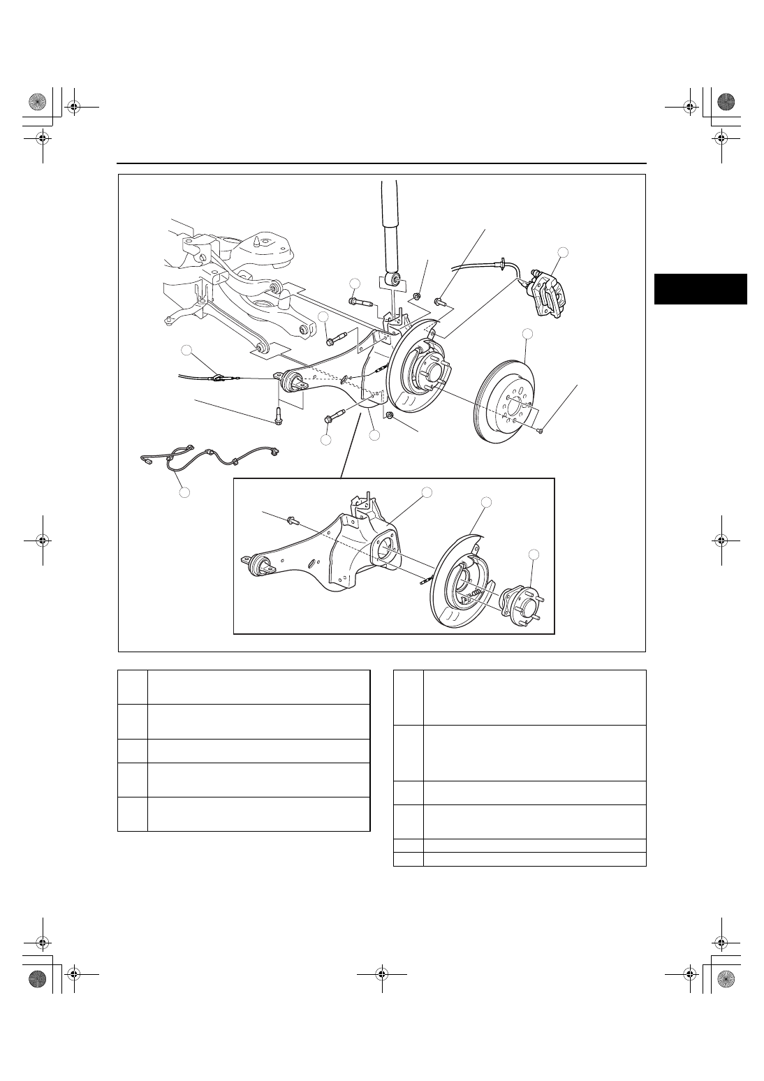
REAR SUSPENSION
02-14–13
02-14
.
N·m {kgf·m, ft·lbf}
98—120
{10.0—12.2,
72.3—88.5}
75.5—102
{7.70—10.4,
55.7—75.2}
75.5—102
{7.70—10.4,
55.7—75.2}
75.5—102
{7.70—10.4,
55.7—75.2}
78.4—101.9
{8.00—10.3,
57.9—75.1}
97.7—132.3
{9.97—13.49,
72.06—97.57}
1
8
10
5
3
7
6
9
2
4
9.8—14.7 N·m
{100—149 kgf·cm,
87—130 in·lbf}
11
acxuuw00001785
1
ABS wheel-speed sensor
(See 02-14-14 ABS Wheel-speed Sensor Removal
Note)
2
Parking brake cable
(See 04-12-3 PARKING BRAKE REMOVAL/
INSTALLATION[2WD].)
3
Caliper component
(See 02-14-14 Caliper Component Removal Note)
4
Disc plate
(See 04-11-22 REAR BRAKE (DISC) REMOVAL/
INSTALLATION.)
5
Bolt (rear shock absorber lower side)
(See 02-14-14 Bolt (Rear Shock Absorber Lower
Side) Removal Note)
6
Bolt (rear lateral link outer side)
(See 02-14-14 Bolts (Rear Lateral Link Outer Side
And Rear Upper Arm Outer Side) Removal Note.)
(See 02-14-14 Bolts (Rear Lateral Link Outer Side
And Rear Upper Arm Outer Side) Installation Note.)
7
Bolt (rear upper arm outer side)
(See 02-14-14 Bolts (Rear Lateral Link Outer Side
And Rear Upper Arm Outer Side) Removal Note.)
(See 02-14-14 Bolts (Rear Lateral Link Outer Side
And Rear Upper Arm Outer Side) Installation Note.)
8
Trailing link, rear wheel hub component and parking
brake component
9
Rear wheel hub component
(See 03-12-3 WHEEL HUB COMPONENT
REMOVAL/INSTALLATION[2WD])
10
Parking brake component
11
Trailing link
1871-1U-06B(02-14).fm 13 ページ 2006年3月15日 水曜日 午前11時1分