Mazda CX 7. Manual - part 160
WHEEL AND TIRES
02-12–1
02-12
2007 Mazda CX-7 Workshop Manual (1871–1U–06B)
Revised 3/2007 (Ref. No. R051/07)
02-12
WHEEL AND TIRES
WHEEL AND TIRE SPECIFICATION . . . 02-12–1
WHEEL BALANCE ADJUSTMENT . . . . 02-12–2
Adhesive-type Balance Weight
(Outer). . . . . . . . . . . . . . . . . . . . . . . . 02-12–2
Knock-type Balance Weight (Inner) . . . 02-12–3
Remaining Amount of Unbalance
Confirmation. . . . . . . . . . . . . . . . . . . . 02-12–3
TIRE PRESSURE ADJUSTMENT
(WITH TPMS) . . . . . . . . . . . . . . . . . . . . 02-12–3
WHEEL UNIT ID REGISTRATION . . . . . . 02-12–4
Using M-MDS . . . . . . . . . . . . . . . . . . . . 02-12–4
Without Using M-MDS. . . . . . . . . . . . . . 02-12–4
WHEEL UNIT
REMOVAL/INSTALLATION . . . . . . . . . . 02-12–4
Valve Core Removal Note . . . . . . . . . . . 02-12–5
Wheel Unit Removal Note . . . . . . . . . . . 02-12–5
Wheel Unit Installation Note . . . . . . . . . 02-12–6
End of Toc
WM: WHEELS AND TIRES
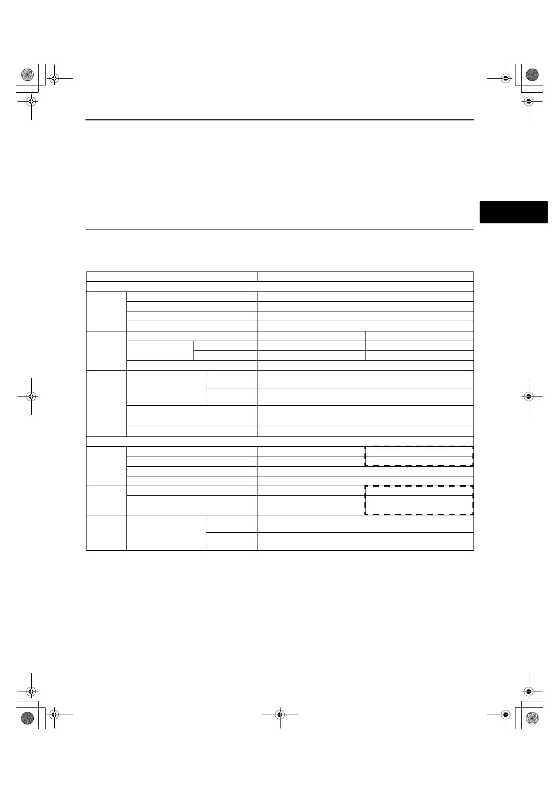
WHEEL AND TIRE SPECIFICATION
id021200800100
Wheel and tire
*
1
: Total weight exceeds 160 g {5.65 oz}.
*
2
: One balance weight: 60 g {2.12 oz} max. If the total weight exceeds 100 g {3.53 oz} on one side, rebalance
after moving the tire around on the rim. Do not use three or more balance weights.
End Of Sie
Item
Specification
Standard tire and wheel
Wheel
Size
18
× 7 1/2J
Offset
(mm {in})
50 {1.97}
Pitch circle diameter
(mm {in})
114.3 {4.50}
Material
Aluminum alloy
Tire
Size
P235/60R18 102H
235/60R18 103H (Mexico spec.)
Air pressure
(kPa {kgf/cm
2
, psi})
Front
220 {2.2, 32}
230 {2.3, 34} (Mexico spec.)
Rear
220 {2.2, 32}
230 {2.3, 34} (Mexico spec.)
Remaining tread
(mm {in})
1.6 {0.06}
Wheel and
tire
Wheel and tire runout
Radial
direction
1.5 {0.06} max.
(mm {in}) Lateral
direction
2.0 {0.08} max.
Wheel imbalance
(g {oz})
Adhesive-type*
1
: 10 {0.35} max.
Knock-type*
2
: 6 {0.21} max.
Tightening torque
(N·m {kgf·m, ft·lbf})
88.2—117.6 {9.00—11.99, 65.06—86.73}
Temporary spare tire
Wheel
Size
18
× 4T
16
× 5J
Offset
(mm {in})
40 {1.57}
45 {1.77}
Pitch circle diameter
(mm {in})
114.3 {4.50}
Material
Steel
Tire
Size
T155/90D18 103M
205/80R16 100M
Air pressure
(kPa {kgf/cm
2
, psi})
420 {4.2, 60}
250 {2.5, 36}
Wheel and
tire
Wheel and tire runout
Radial
direction
2.0 {0.08} max.
(mm {in}) Lateral
direction
2.5 {0.10} max.