Mazda CX 7. Manual - part 154
ON-BOARD DIAGNOSTIC
02-02–5
02-02
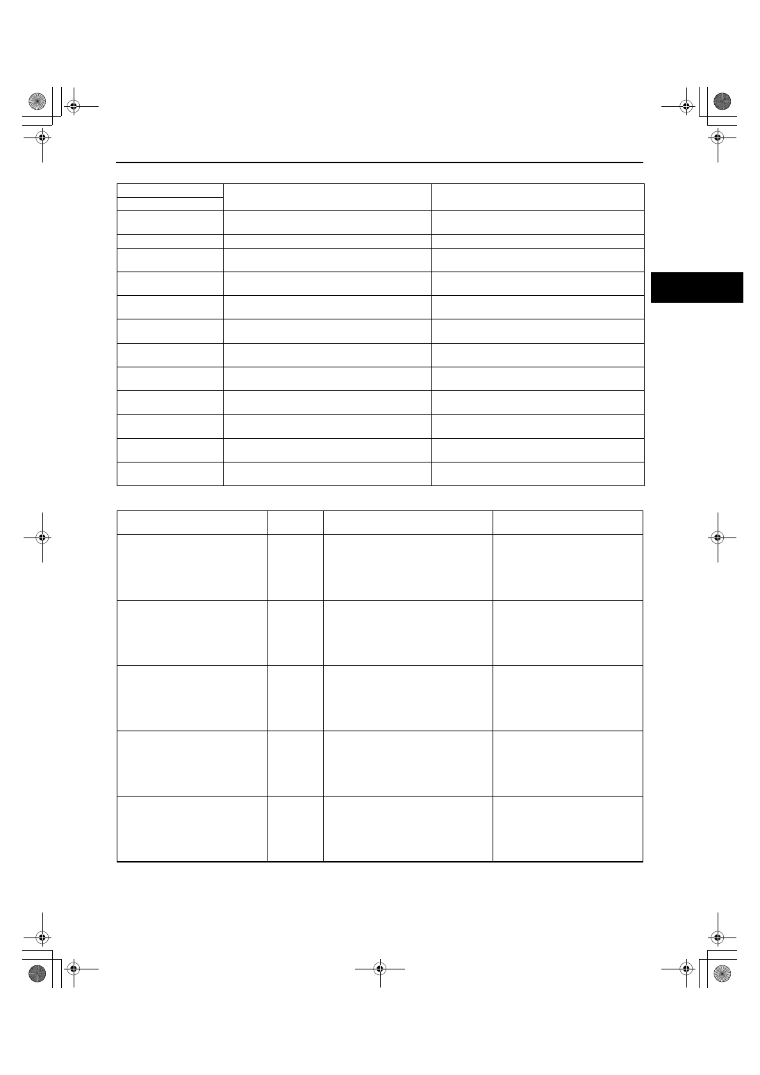
DTC Table
PID/DATA Monitor Table
DTC
Description
Page
M-MDS
B1342
Instrument cluster internal malfunction
(See 09-02E-5 DTC B1342[INSTRUMENT
CLUSTER].)
B2143
ID registration failure
(See 02-02-8 DTC B2143.)
B2477
Instrument cluster configuration not performed
(See 09-02E-5 DTC B2477[INSTRUMENT
CLUSTER].)
B2868
Wheel unit No.1 internal malfunction
(See 02-02-8 DTC B2868, B2869, B2870,
B2871.)
B2869
Wheel unit No.2 internal malfunction
(See 02-02-8 DTC B2868, B2869, B2870,
B2871.)
B2870
Wheel unit No.3 internal malfunction
(See 02-02-8 DTC B2868, B2869, B2870,
B2871.)
B2871
Wheel unit No.4 internal malfunction
(See 02-02-8 DTC B2868, B2869, B2870,
B2871.)
U0127
Communication failure between instrument
cluster and keyless receiver
(See 02-02-9 DTC U0127.)
U2616
Wheel unit No.1 (No response)
(See 02-02-11 DTC U2616, U2617, U2618,
U2619.)
U2617
Wheel unit No.2 (No response)
(See 02-02-11 DTC U2616, U2617, U2618,
U2619.)
U2618
Wheel unit No.3 (No response)
(See 02-02-11 DTC U2616, U2617, U2618,
U2619.)
U2619
Wheel unit No.4 (No response)
(See 02-02-11 DTC U2616, U2617, U2618,
U2619.)
PID Name
(Definition)
Unit/
Condition
Condition/Specification
Action
AI_WU1_ID
AI_WU2_ID
AI_WU3_ID
AI_WU4_ID
(Wheel unit ID code (during ID
registration))
–
Indicates the wheel unit ID code.
(During wheel unit ID registration.)
• Replace the wheel unit.
• Perform the wheel unit ID
registration.
AI_WU1_P
AI_WU2_P
AI_WU3_P
AI_WU4_P
(Tire pressure value (during ID
registration))
Pa/psi
Indicates the tire pressure. (During ID
registration.)
• Adjust tire pressure.
• Replace the wheel unit.
• Perform the wheel unit ID
registration.
FFD1_WU1_P
FFD1_WU2_P
FFD1_WU3_P
FFD1_WU4_P
(Tire pressure value (freeze frame
PID data 1))
Pa/psi
Indicates the tire pressure. (Freeze
frame PID data 1)
Adjust tire pressure.
FFD2_WU1_P
FFD2_WU2_P
FFD2_WU3_P
FFD2_WU4_P
(Tire pressure value (freeze frame
PID data 2))
Pa/psi
Indicates the tire pressure. (Freeze
frame PID data 2)
Adjust tire pressure.
FFD1_WU1_T
FFD1_WU2_T
FFD1_WU3_T
FFD1_WU4_T
(Internal tire air temperature value
(freeze frame PID data 1))
°C/°F
Indicates the internal tire air
temperature. (Freeze frame PID data 1)
Adjust tire pressure.
1871-1U-06B(02-02).fm 5 ページ 2006年3月15日 水曜日 午前10時56分